manuals.online logo
Brands
  1. Home
  2. •
  3. Brands
  4. •
  5. Lamp
  6. •
  7. Door Opening System
  8. •
  9. Lamp HDSN-30K User manual

Lamp HDSN-30K User manual

木扉、45mm幅アルミ枠扉取付部品
 
付属品ではありません。
 
別途ご用意ください。
(推奨M3.5〜4
)
※座金取付用ねじ
20mm幅アルミ枠扉取付部品
7
5
バインドタッピンねじ
3.5 15  4ヶ

6
4
HDSN-SZ座金
1ヶ

トラス小ねじM46 
1ヶ
1

8
HDSN-AZ座金
1ヶ
別梱包部品(どちらか選択)
HDSN-30(左) 1ヶ 
2 マウンティングプレート 1ヶ 3 バインドタッピンねじ
3.5 15  3ヶ

別売 別売
トラス小ねじM46
1ヶ 2ヶ
PAT.P
R
1 HDSN-30(右) 1ヶ 
2 マウンティングプレート 1ヶ 3 バインドタッピンねじ
3.51 5 3ヶ
PAT.P
R
本品を取り付ける扉高さ、扉質量から下記式に従って扉トルクを計算し、
表1. より適切な機種を選定してください。 
 扉高さH(m)/ 2 ×扉質量(kg)×9.8=扉トルク(N・m)
表 1. 適用扉範囲
※上記キャビネット以外の取り付けの場合は、弊社営業担当者までお問い合わせください。
■部品明細
取り付け上の注意
●本品は左右セットでご使用ください。
●本品は上開き扉用ステー金具です。これ以外の使用方法や、分解、改造および、「機種の選定方法」に示す仕様範囲外の扉に使用したこと等が原因に
 による故障、けが等の事故につきましてはその責任を一切負い兼ねますのであらかじめご了承ください。
●本品のキャビネットへの取り付けは、本書に従い正しく施工してください。指定寸法以外の寸法で取り付けた場合、本品の性能が発揮できないばかり
 でなく、破損等による思わぬけがをする恐れがあります。
●本品の取り付けには、付属のねじを使用してください。付属以外のねじを使用すると本品がはずれたり、けがをする恐れがあります。
●改良等により予告なく寸法、仕様が変わることがあります。詳細は現品にてご確認ください。
●扉は反り、ねじれが発生しにくい構造にしてください。
使用上の注意
●扉が開ききった状態からさらに開こうとしたり、本品の機能であるダンパー作用による、ゆっくりと閉じようとする扉を必要以上の力で閉める等、
 無理な扉の開閉は絶対におやめください。故障の原因となります。
●本品の使用温度範囲は 0℃〜 40℃です。温度変化により扉の開閉速度は変化しますが、故障ではありません。
 使用温度範囲以外でのご使用はおやめください。発熱するマイクロオーブンレンジ等のキャビネットには絶対に使用しないでください。
●ご使用になる際は、アームに指をはさまないようにご注意ください。思わぬけがをする恐れがあります。
●取付ねじにゆるみが無いことを定期的に確認してください。ゆるみがあった場合は、増し締めを行ってください。
図 1. 部品明細図
注

意
以下の注意事項をお守りいただかない場合、思わぬけがをしたり、周辺の家財に損害を与えたりする恐れがあります。
吊元には、かぶせタイプ・キャッチなしのスライド丁番をご使用ください。
推奨品 ランプ印 スライド丁番 230シリーズ
    品番 230-26/ 1 9T(キャッチなし)
■機種の選定方法
図 2. キャビネット図
H
T
W
1
0
W
0
このたびは、弊社製品をお買い上げいただき、まことにありがとうございます。
取付作業前に本説明書をよくお読みの上、正しく取り付けを行ってください。
誤った取り付けは、思わぬけがをする恐れがありますので、おやめください。
本説明書をお読みになった後は、いつでも取り出せる場所に保管してください。
ソフトダウンステー重量用HDSN-30型取付説明書

HDSN-30K /HDSN-30M /HDSN-30H /HDSN-30S
●キャビネットおよび扉の設計、本品の取付位置は必ず指定寸法、水平、垂直度をお守りください。1枚の扉に複数個の製品を使用する場合、取付位置に
差異がありますと、いずれかの製品に荷重負担が集中し、製品の寿命や機能に影響する可能性があります。取付時には十分にご注意ください。
●本品の側板および扉への取り付けは、垂直度を確実にお守りください。
扉トルク
90°開き
機種 80°開き
HDSN-30KR
HDSN-30KL
HDSN-30ML
HDSN-30MR
HDSN-30HL
HDSN-30SR
HDSN-30SL
HDSN-30HR
13.7 〜 17.5N・m(140 〜 179kgf・cm)/2本使い
17.6〜 21.5N・m(180 〜 219kgf・cm)/2本使い
21.6 〜 25.4N・m(220 〜 259kgf・cm)/2本使い
25.5 〜 29.4N・m(260 〜 300kgf・cm)/2本使い
13.7 〜 19.5N・m(140 〜 199kgf・cm)/2本使い
19.6 〜 24.4N・m(200 〜 249kgf・cm)/2本使い
24.5 〜 29.3N・m(250 〜 299kgf・cm)/2本使い
29.4 〜 34.3N・m(300 〜 350kgf・cm)/2本使い
本取付説明書の製品内容は、部品としての品質範囲です。本製品を使用した最終製品の機能・性能・安
全性を保証するものではありません。必ず、最終製品でのご確認をいただくよう、お願いいたします。
製品については万全を期しておりますが、万一不良品があった場合、ご購入先へお問い合わせくださ
い。保証期間は弊社納品書発行より1年間とさせていただき、良品との交換をもって責任の範囲とさ
せていただきます。
十字穴付き 十字穴付き
十字穴付き十字穴付き 十字穴付き
■取付寸法図本図は 90 開きの図面です。80 開きは ( ) 内寸法です。
取付寸法図・取付手順

図4.
スライドヒンジ基準点
157.5
ー
S
(167
ー
S)
173.5
ー
S
(183
ー
S)
S
A =134
ー
D
B =15+ T


ー

0
W =キャビネット外幅
0
T =キャビネット側板の板厚
W =扉幅
S =かぶせ量
C =側板からアルミ枠側面までの距離
1
0
)
1
0
W
ー
W
(2
C(1〜4mm)
パッキン厚D(推奨3〜5mm)
16
ガラス
5.5(扉内側基準)
6
20
50
側板
アルミ枠
115(124.5)
32
9
B(扉端面基準)
32
図5.
A
扉
■取付手順
図3.
手順1.マウンティングプレート②をキャビネット内側の規定位置(図3.参照)に
    付属の十字穴付きバインドタッピンねじ3.5  1 5 ③で確実に固定します。
手順2.
●座金 HDSN-SZ(木扉、45mmアルミ枠扉)を使用する場合
 
   
HDSN-SZ 座金④をご使用の場合、座金の長穴を扉裏面の規定位置 ( 図
  
  
3. 参照 ) に、付属の十字穴付きバインドタッピンねじ3.515⑥で仮り止め
します。
    
●座金 HDSN-AZ(20mmアルミ枠扉)を使用する場合
    HDSN-AZ 座金⑦をご使用の場合、取付ねじは付属していないため、
    別途ご用意ください。( 推奨 M3.5 〜 4 )
   
 
ご用意いただいた取付ねじで規定位置 ( 図 4 . 参照 ) に確実に固定してく
    ださい。

  
  
※ HDSN-AZ 座金⑦は、図 5 に示す側板とアルミ枠側面の距離 C の寸法
  
  
 
を1mm から 4mm の範囲内で設定してください。 
本図は木扉、45mm幅アルミ枠扉、(HDSN-SZ)の取付寸法図です。20mm幅アルミ枠扉(HDSN-AZ) は図4、図5を参照ください。 
手順 3. HDSN 本体①の穴をマウンティングプレート②の軸に合わせ、パチンと音
    

がする根元まで確実に差し込みます。
  
   
 
HDSN 本体①をマウンティングプレート②に差し込む際、ハンマー等で
    叩くことはおやめください。故障や破損の原因となります。
手順 4. HDSN-SZ 座金④の軸とアーム先端穴を合わせ、十字穴付きトラスねじ
    M4  6 ⑤を差し込みます。
手順 5. 扉開閉の動作確認を行い、HDSN-SZ 座金④の長穴で座金の位置を調節し、
   
 
確実に固定します。
手順 6.  アームを座金から外し、座金の丸穴に十字穴付きバインドタッピンねじ⑥を
   
 
ねじ込み座金を確実に固定します。
手順 7.  再度、アームを座金の軸に差し込み、十字穴付きトラスねじM4  6 ⑤で
   
 
確実に締め込みます。(HDSN-AZは図10.)
本図は木扉、45mm幅アルミ枠扉、(HDSN-SZ)の取付方法です。20mm 幅アルミ枠扉(HDSN-AZ)の取付方法は図8、図10を参照ください。 
図6.
ユニットを取り付ける前に、吊元にスライド丁番を規定の位置に取り付け、扉がスムーズに開閉するようにスライド丁番を調整してください。
スライド丁番の位置調整は座金 HDSN-SZ または HDSN-A Z を取り付ける前に行なってください。座金を取り付けた後に扉の位置調整を行うと本体のアームが図 6 の様に左右へ
ひずみ、故障や破損の原因となりますのでおやめください。
手順4
手順7
手順5
手順6
バインドタッピンねじ3.5 15
(手順2と手順7のねじ4本 を 締 結 )
トラスねじM4 6
5
6
トラスねじM4 6
8
図10.
バインドタッピンねじ3.5 15
3.515
手順2
手順1
手順3
ンド タッピ ン ね じ バイ
(長穴部仮止め)
HDSN本体
扉
HDSN-SZ
側板
図8.
(お客様でご用意ください) 
座金取付ねじ
マウンティング
プレート
1
HDSN-AZ
7
36
4
2
図7.図9.
十字穴付き 十字穴付き
十字穴付き
十字穴付き
十字穴付き
2014.10 PRINTEDINJAPAN 0255-3 
■Type selection method
Cautions for operation
the symptom of troubles. It is prohibited to use this mechanism at the temperature exceeding the specified range. It is not permitted to apply this
mechanism for the cabinet installing a heat-generating microwave oven or other similar appliances.
It is necessary to periodically check the fixing screws for loosing. Tighten the loosed screws as required.
Keep a door from forced opening and closing. It is prohibited to open a door over a full open angle or to close a door with excess force.
●
The working temperature range of this mechanism is 0~40°C. Opening and closing speed of the door depends on the temperature.This is not
●
Be careful not to insert a finger into the arm mechanism of the unit. Sever injury may be caused.
●
●The right-hand and left-hand side bodies of this mechanism should be installed in set.
●This is the mechanism exclusively for a flap type door application. Be reminded that we can not take the responsibility for damages and injuries caused
by other applications, disassembly, conversion and the application to the door exceeding the standard ranges shown in the item ”Type selection meth-
od”.
●This mechanism must be installed to the cabinet correctly in accordance with the indications of this manual. Notice that the non-observance of the
specified dimensions not only does not enable this mechanism to show its full performance, but also may result in damage and also cause injury.
●It is necessary to use the attached screws for installing this mechanism. Otherwise the disconnection of this mechanism may happen causing injury.
●For improvement the specification may be changed without notice. As for details please verify the actual goods.
●The applicable door must have the construction for which it is difficult to induce bent or torsion.
Any failure to observe the following cautions may result in personal injury and property damage.
CAUTION
Cautions for installation
※Screws for fixing
mounting plate are NOT
included.
Prepare 2 pcs of screw
separately. (M3.5~4 is recommended.)
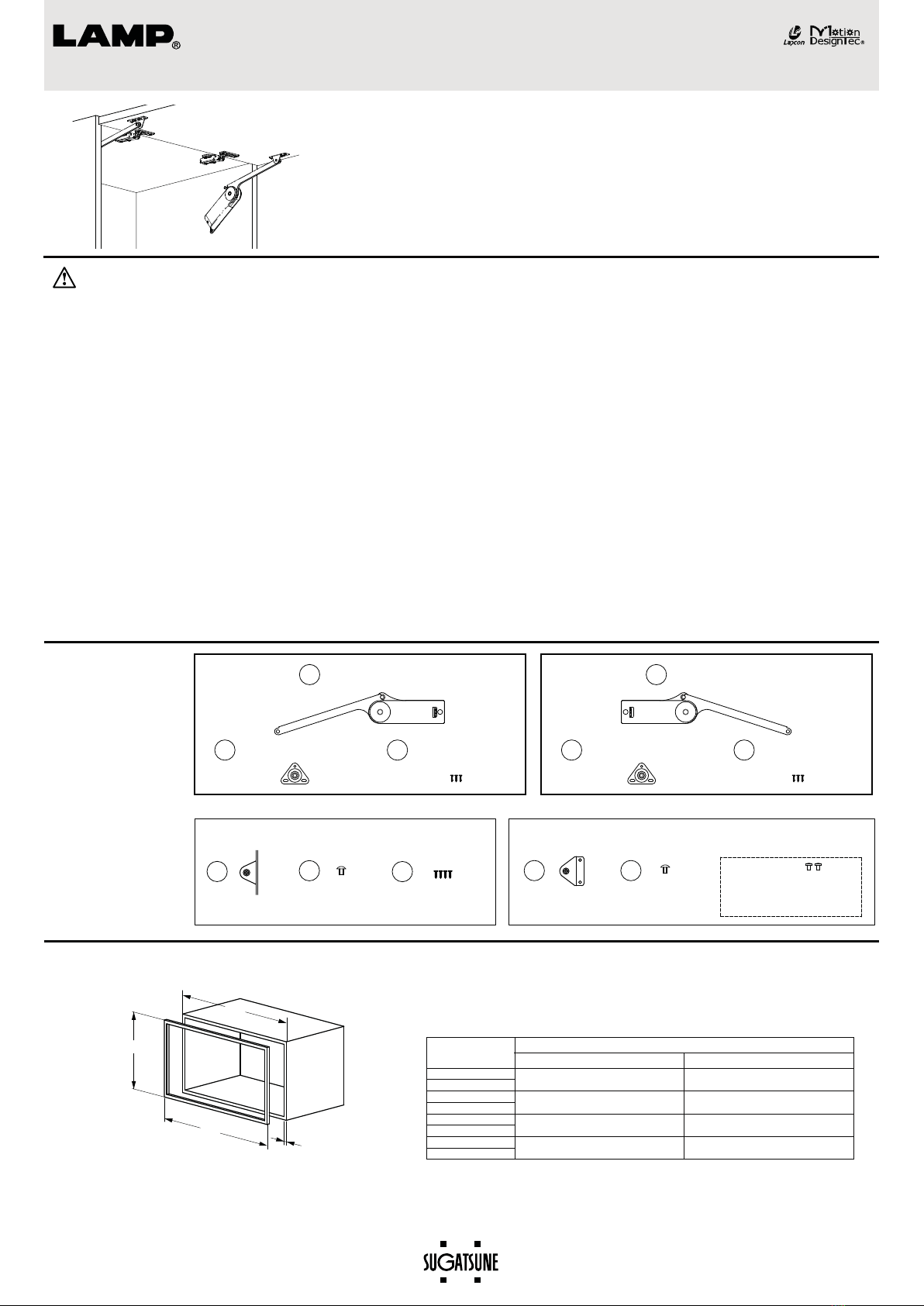
Parts for installing to 20mm width aluminum frame door
7
5
Bind tapping screw
(3.5x15) 4pcs

6
4
HDSN-SZ mounting
plate 1pc
Truss screw (M4x6)
1pc
1


8
HDSN-AZ mounting
plate 1pc
Parts of separate packing (Select either)
HDSN-30 body / left-hand side 1pc
2

Body mounting plate 1pc 3

Bind tapping screw
(3.5x15) 3pcs

Truss screw (M4x6)
1pc
PAT.P
R
1

HDSN-30 body / right-hand side 1pc
2

Body mounting plate 1pc 3

Bind tapping screw
(3.5x15) 3pcs
PAT.P
R
Parts for installing to solid wooden door
or 45mm width aluminum frame door
Option Option
2 pcs
The slide hinge (overlay use, non-catch type) should be used as a
door- hanging device.
The LAMP brand 230 series slide hinge (product No. 230-26/19T,
non-catch type) is recommended.
Fig.2.Cabinet
H
T
W
1
0
W
0
HDSN-30 HEAVY - DUTY SOFT - DOWN STAY
INSTALLATION MANUAL
Read this manual carefully for proper installation and operation.
Incorrect installation and improper use of the product may cause damage to the unit and also cause injury.
This manual should be kept by the user after installation.
Fig. 1. Part description
■
Part description
Calculate the door torque according to the following formula considering the weight and the
height of the applicable door. Select the suitable type as per Table 1.
※Contact our sales representatives in case of installing to a cabinet exceeding the
indicated ranges.
Door height H (m) /2 x Door weight (kg) x 9.8 = Door torque (N・m)
Table 1. Type and suitable door range
Door torque
Opening angle 90°
Type Opening angle 80°
HDSN-30KR
HDSN-30KL
HDSN-30ML
HDSN-30MR
HDSN-30HL
HDSN-30SR
HDSN-30SL
HDSN-30HR
13.7 〜17.5 N・m ( 140 〜179 kgf・cm ) / pair
17.6〜21.5 N・m ( 180 〜219 kgf・cm ) / pair
21.6 〜25.4 N・m ( 220 〜259 kgf・cm ) / pair
25.5 〜29.4 N・m ( 260 〜300 kgf・cm ) / pair
13.7 〜19.5 N・m ( 140 〜199 kgf・cm ) / pair
19.6 〜24.4 N・m ( 200 〜249 kgf・cm ) / pair
24.5 〜29.3 N・m ( 250 〜299 kgf・cm ) / pair
29.4 〜34.3 N・m ( 300 〜350 kgf・cm ) / pair
●Make sure that installation position and specifications are followed. Unsuitable installation position may damage the mechanism when in case two
stays are used together.
●Make sure that the arm of the stay is parallel with the side panel of the cabinet.
Sugatsune guarantees the quality of this product as for all its parts. It cannot however guarantee the final
assembly as a whole.
This product was manufactured and delivered with our utmost care. Should you however find any defect,
please contact your dealer immediately.
Sugatsune warrants that this product is free from defect for a period of one (1) year from the date of
delivery.
Sugatsune liability is limited to the replacement of this product by a similar one free of defect. In no case
does this extend to the replacement of the installation or the cabinet as a whole.
■
The dimensions in case of the 90opening door are sho wn in the following figures. The dimensions in case of the 80opening door are sho wn in ( ).
MOUNTING DIMENSIONS
Fig. 4
Hinge center for slide hinge
(dimension standard plane)
S
A=134
ー
D
B=15+T

ー

0
W=Cabinet overall width
0
T=Cabinet side board thickness
W=Door width
S=Overlay
C=Distance from the side board inside surface
  to the aluminum frame side surface
1
0
)
1
0
W
ー
W
(2
C(1〜4mm)
Rubber gasket thickness D (3-5 is recommended)
16
Glass
5.5 (from the door inside plane)
6
20
50
Side board
Aluminum frame
9
B
(from the door
side end plane)
32
Fig. 5
A
157.5
ー
S
(167
ー
S)
173.5
ー
S
(183
ー
S)
32
115(124.5)
Step 4
Step 7
Step 5
Step 6
Bind tapping screw 3.5x15
(Tighten 4 screws of Step 2 and Step 7)
Truss screw M4x6
5
6
Truss screw M4x6
8
Fig. 10
Bind tapping screw 3.5x15
3.515
Step 2
Step 1
Step 3
Bind tapping screw
(Oblong hole for temporary fixing)
HDSN-30 body
Door
HDSN-SZ
Side board
Body mounting
plate
1
36
4
2
Fig.8
(Prepare separately) 
Screws for fixing the mounting plate
HDSN-AZ
7
Fig. 3
Step 1.Place the mounting plate ②to the specified position of the inside surface of
   a cabinet and fix it with the attached bind tapping screws 3.5x15 ③firmly. 
Step 2.
●In case of HDSN-SZ mounting plate (for solid wooden
 
door or 45mm width aluminum frame door )
Temporarily fix the HDSN-SZ mounting plate ④through its oblong hole to the
specified position of the back of the door with the attached bind tapping screws
3.5x15 ⑥.
●In case the HDSN-AZ mounting plate (for 20mm width
 
aluminum frame door)
The fixing screws are not supplied. Prepare them separately (M3.5-4 is
recommended).Fix the HDSN-AZ mounting plate ⑦with the prepared fixing
screws firmly. (Fig. 4)
※The HDSN-AZ mounting plate ⑦should be mounted so that the distance (C)
between the side board inside surface and the aluminum frame side surface be
in the range of 1~4mm. (Fig. 5) 
This drawing shows the case of installation to solid wooden door or 45mm width aluminum frame door (HDSN-SZ). As for the case of installation to
20mm width aluminum frame door (HDSN-AZ), refer to Fig. 4 and 5.
Step 3.Put the hole of the HDSN-30 side body ①to the axis of the body mounting
    plate ②, insert the unit body up to the root of the plate making click.  
Never use a hammer or others like it in order to insert the mounting plate
into the HDSN-30 body ①. Otherwise trouble or damage may happen.
Step 4. Adjusting the axis of the HDSN-SZ mounting plate ④and the hole in the  
    arm end, insert the truss screw M4x6 ⑥.
Step 5.
 
Check the door opening and closing function and adjust the position of the
    HDSN-SZ mounting plate ④through its oblong hole.
Step 6.
 
Remove the arm from the mounting plate. Then, fix the plate firmly with the
    bind tapping screw ⑥into its circular hole.
Step 7.
 
Insert the arm into the axis of the mounting plate again and fix the arm firmly
    with the truss screw M4x6 ⑤. (Fig. 10 (HDSN-AZ)
Fig.7
This shows the installation procedure for the application of solid wooden door or 45mm width aluminum frame door (HDSN-SZ).
In case of the installation procedure for the application of 20mm width aluminum frame door (HDSN-AZ), refer to Fig. 9 and 10.
Fig.9
Door
Fig.6
Before installing the unit, mount the slide hinge to the specified position and adjust it so that the door can be opened and closed smoothly.
The position adjustment of the slide hinge should be carried out before installing the HDSN-SZ or HDSN-AZ mounting plate. Otherwise the stay arm may be deflected right or left as
shown in Fig. 6, which may result in trouble or damage.
■INSTALLATION PROCEDURE

This manual suits for next models

3

Other Lamp Door Opening System manuals

Lamp FD35EV User manual

Lamp

Lamp FD35EV User manual

Lamp FD50-H User manual

Lamp

Lamp FD50-H User manual

Lamp Lapcon J160 User manual

Lamp

Lamp Lapcon J160 User manual

Lamp LDD-S User manual

Lamp

Lamp LDD-S User manual

Lamp FD30EX User manual

Lamp

Lamp FD30EX User manual

Lamp FD30EX User manual

Lamp

Lamp FD30EX User manual

Lamp KF111-H User manual

Lamp

Lamp KF111-H User manual

Lamp AZ-GD231 User manual

Lamp

Lamp AZ-GD231 User manual

Lamp FD50-H User manual

Lamp

Lamp FD50-H User manual

Lamp FD30-F User manual

Lamp

Lamp FD30-F User manual

Lamp FD35EV User manual

Lamp

Lamp FD35EV User manual

Lamp AZ-AT230-HL Instruction Manual

Lamp

Lamp AZ-AT230-HL Instruction Manual

Lamp FD50-H User manual

Lamp

Lamp FD50-H User manual

Lamp FD50-H User manual

Lamp

Lamp FD50-H User manual

Lamp FD80-H User manual

Lamp

Lamp FD80-H User manual

Lamp FD50-H User manual

Lamp

Lamp FD50-H User manual

Lamp FD80-AFH User manual

Lamp

Lamp FD80-AFH User manual

Lamp HC-70 User manual

Lamp

Lamp HC-70 User manual

Lamp HC-30L User manual

Lamp

Lamp HC-30L User manual

Lamp MonoFlat FAD-5 User manual

Lamp

Lamp MonoFlat FAD-5 User manual

Lamp FM150PRO User manual

Lamp

Lamp FM150PRO User manual

Lamp KF28 User manual

Lamp

Lamp KF28 User manual

Lamp XL-GC07D-CR User manual

Lamp

Lamp XL-GC07D-CR User manual

Lamp HCZ-80 User manual

Lamp

Lamp HCZ-80 User manual

Popular Door Opening System manuals by other brands

CAME V700E installation manual

CAME

CAME V700E installation manual

Bohle BO 5215430H instruction manual

Bohle

Bohle BO 5215430H instruction manual

Tormax iMotion 1401 manual

Tormax

Tormax iMotion 1401 manual

Siemens SIDOOR ATE530S operating instructions

Siemens

Siemens SIDOOR ATE530S operating instructions

EUROLAIKAS FS 1000 Installation instructions and user guide

EUROLAIKAS

EUROLAIKAS FS 1000 Installation instructions and user guide

Siemens RHFF manual

Siemens

Siemens RHFF manual

quiko Swingy QK-SW80 user manual

quiko

quiko Swingy QK-SW80 user manual

Dormakaba 8900 EMR installation instructions

Dormakaba

Dormakaba 8900 EMR installation instructions

Clever Life CL-C-GD811 user manual

Clever Life

Clever Life CL-C-GD811 user manual

Metaflex Medicare EI1 2.0 installation manual

Metaflex

Metaflex Medicare EI1 2.0 installation manual

cinetto PB15 Assembly instructions

cinetto

cinetto PB15 Assembly instructions

Auta 700105 manual

Auta

Auta 700105 manual

GAL MOM How to connect

GAL

GAL MOM How to connect

GEZE Slimdrive EMD-F Installation and service instructions

GEZE

GEZE Slimdrive EMD-F Installation and service instructions

Micom 2ES ALE instruction manual

Micom

Micom 2ES ALE instruction manual

Siemens 3VA9578-0LB10 operating instructions

Siemens

Siemens 3VA9578-0LB10 operating instructions

Iseo ACE IS9100 Mounting instructions

Iseo

Iseo ACE IS9100 Mounting instructions

Dorma TS93-5 PKT 90/119 manual

Dorma

Dorma TS93-5 PKT 90/119 manual

manuals.online logo
manuals.online logoBrands
  • About & Mission
  • Contact us
  • Privacy Policy
  • Terms and Conditions

Copyright 2025 Manuals.Online. All Rights Reserved.