manuals.online logo
Brands
  1. Home
  2. •
  3. Brands
  4. •
  5. D+H
  6. •
  7. Door Opening System
  8. •
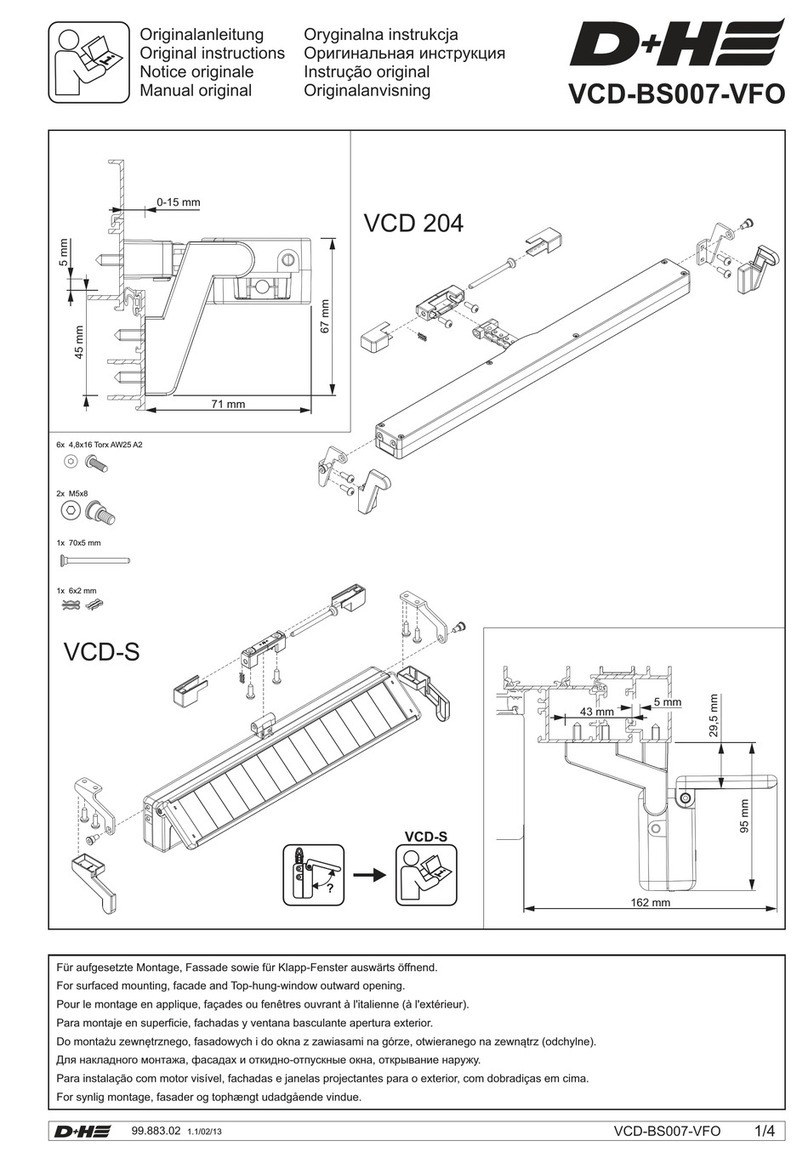
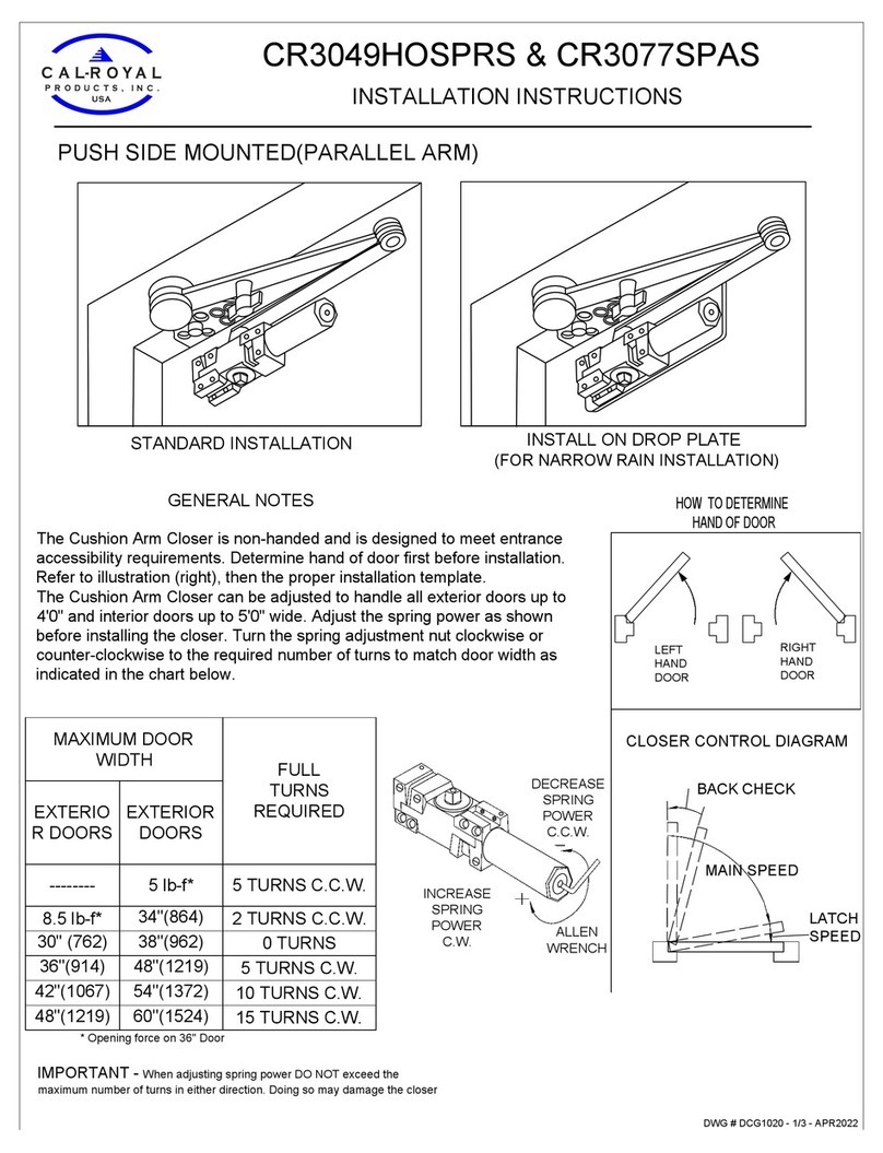
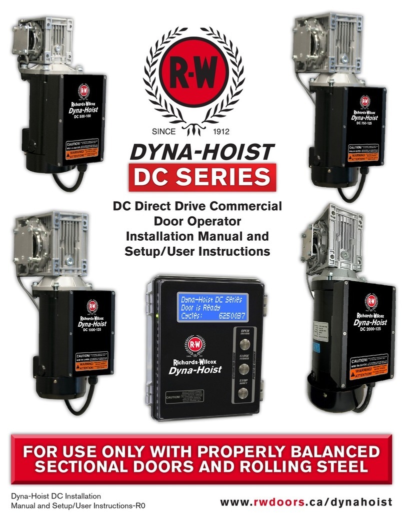
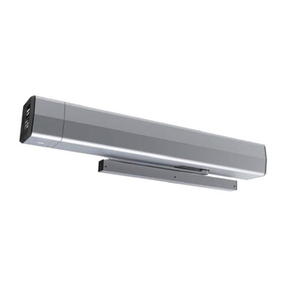
  9. D+H Lamilux SDS-BS025 031 Series User manual

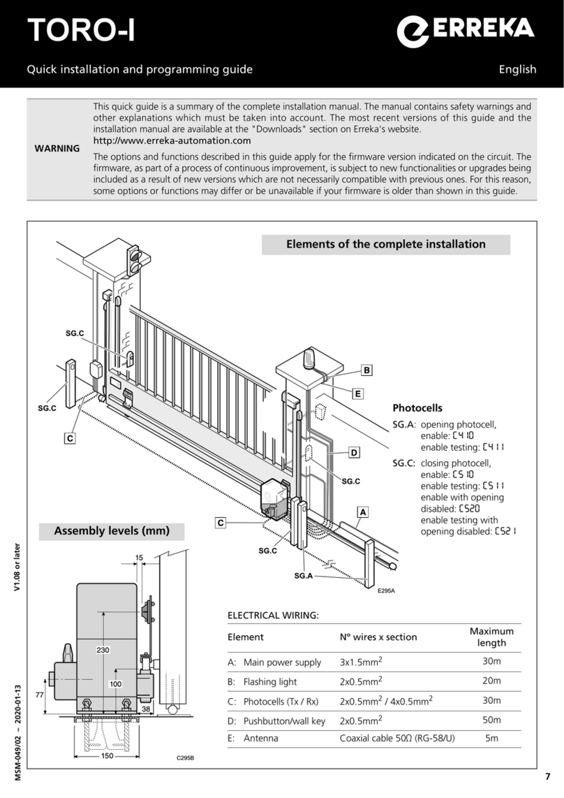
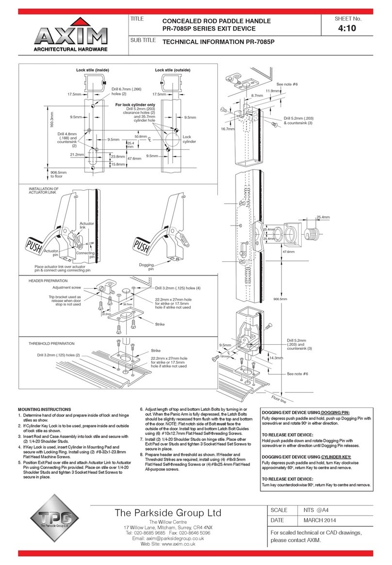
D+H Lamilux SDS-BS025 031 Series User manual

D+H Mechatronic AG • Georg-Sasse-Str. 28-32 • D-22949 Ammersbek • Tel. +4940-605 65 239 • Fax +4940-605 65 254 • www.dh-partner.com
99.824.07 1.1/07/19
© 2010 D+H Mechatronic AG, Ammersbek
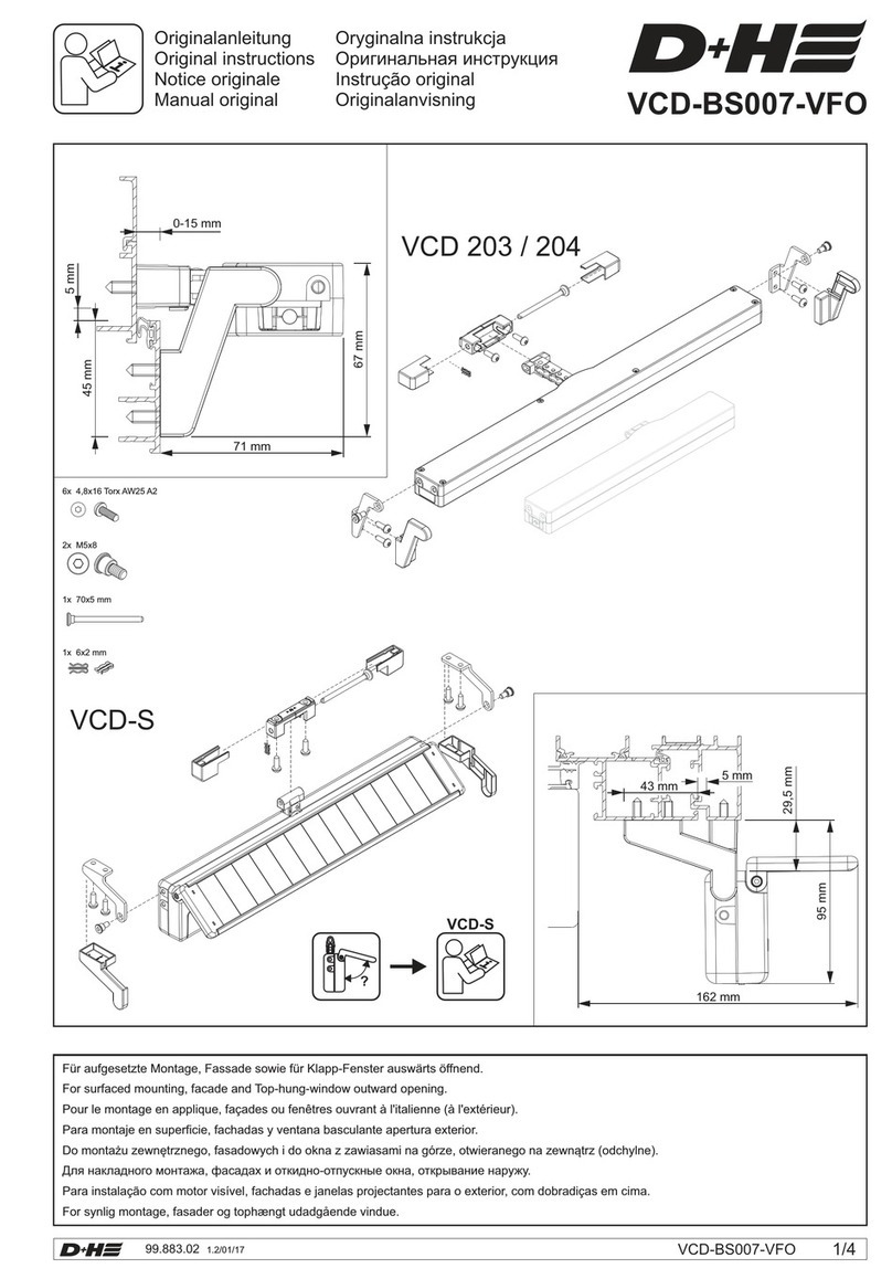
Alle Maße in Millimeter. / All sizes in millimetre.
Technische Änderungen vorbehalten. /
Rights to technical modifications reserved.
SDS 2-DU
SDS 2-DU-24V oder/or
SDS 2-DU-230V
M8 x 20
M10 x 20
Sicherheitshinweise
Einbau und Inbetriebnahme nur durch autorisiertes und qualifiziertes
Fachpersonal!
Wir empfehlen, dieses ausschließlich durch einen D+H-Partner vornehmen
zu lassen, der durch regelmäßige Werksschulungen seine Qualifikation und
Erfahrung sicherstellt.
Grundsätzlich Regenmelder verwenden!
Quetschgefahr im handzugänglichen Bereich!
Beiliegenden roten Sicherheitszettel beachten!
Die bestehenden Vorschriften, z.B. VDE 0833, VDE 0100, DIN 18232, VdS
2221, sowie die Bestimmungen der örtlichen Feuerwehr sind zu beachten.
Falsche Versorgungsspannung kann zur Zerstörung des Antriebes führen!
Tabelle für Leitungslängen und Querschnitte (siehe Anleitung der Zentrale)
beachten!
SDS 2-DU-24V
Betriebsspannung 24 VDC! Antrieb nur mit Schutzkleinspannung betreiben!
SDS 2-DU-230V
Betriebsspannung 230 VAC! L + N nicht vertauschen und den PE an-
schliessen, ansonsten Fehlfunktion und Zerstörung des Antriebes
möglich!
Safety Notes
Mounting and initial operation by qualified and authorized experts
only!
We recommend, that mounting and initial operation is exclusively carried
out by a D+H-distributor, who is highly qualified and experienced by regular
in-house training.
Use always rain detector!!
Danger of violent pressure within reach!
Observe enclosed red safety slip!
Observe existing regulations like e.g. VDE 0100, DIN 18232, VdS guide
lines and EN 12101-2, as well as the regulations of the local fire-brigade.
Wrong distribution voltage can result in destruction of the drive!
Observe table for cable lengths and cross-sections (see instruction for
control panel)!
SDS 2-DU-24V
Operating voltage 24 VDC! Operate drive with protective low voltage only!
SDS 2-DU-230V
Operating voltage 230 VAC! Do not interchange L + N and connect PE
(protective conductor), otherwise malfunction and destruction of the
drive possible!
SL*
Benötigtes Werkzeug/ Required tools
Vor Montagebeginn Maße überprüfen!/
Check dimenension before mounting!
SW 8
Hinweis/ Hint
SW 10, 13, 2x 15, 2x 17
3 mm
SDS-BS025 ... 031
Lamilux
SDS-BS025 ... 031
Montagesatz /
mounting set
Lichtkuppel
Nennbreite/
Domelight
nominal width
*SL
(Strebenlänge/
sash lenght)
1000 mm
1200 mm
1250 mm
Lamilux SK
---
1043 mm
1093 mm
1500 mm 1343 mm
Montageset /
mounting set
SDS-BS028
SDS-BS025/29
SDS-BS026/30
SDS-BS027/31
Lamilux KK
907 mm
1107 mm
1157 mm
1407 mm
Originalanleitung
Original instructions
1/4
01
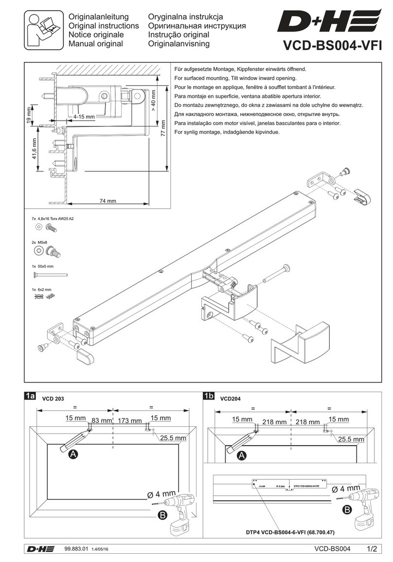
Ggf. Transportsicherung und vormontierte
Konsolenteile entfernen/
If applicable remove transportation lock
and preassembled bracket parts
03
Montage / Mounting Montage / Mounting
02
09
Oberkante/
Top edge
11
==
04a 04b
1/2
1/4 1/4
07
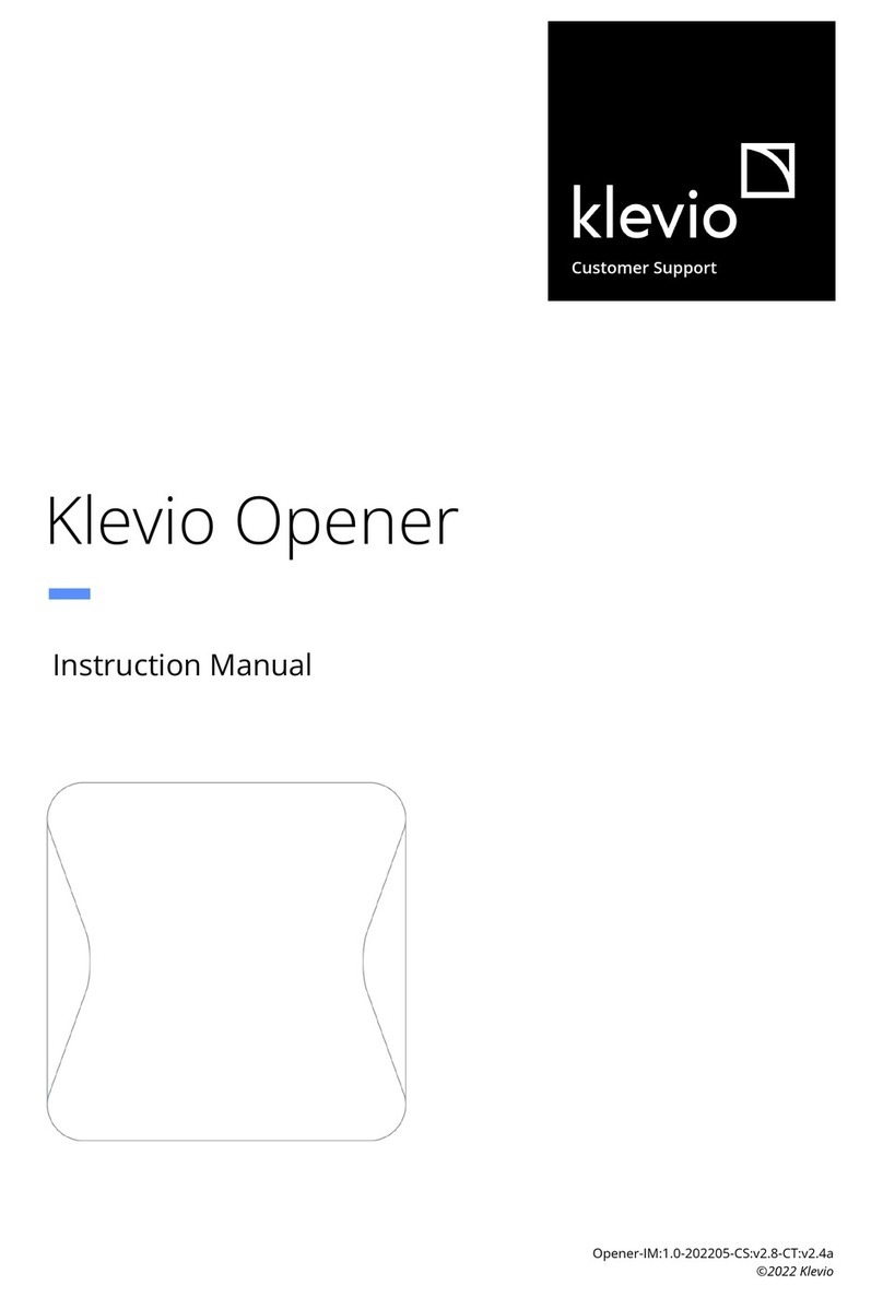
Vormontieren und nach Abb. 4a/4b ausrichten/
Preassamble and align with fig. 4a/4b
Nur bei 2 SDS-Systemen/
Only with 2 SDS-systems
06 Nur bei Bedarf (falsche Montage)/ Only if required! (wrong mounting)
10
11
Anlegekante
Mitte Flügelstrebe SDS 2
99.xxx.xx 1.0/02/09
Montageschablone
Mountingtemplate
Handfest/
Hand-screwed
Ø 3 mm
Einbaurichtung zur Bandseite /
Mounting direction to hinge
05
==
=
=
08a 08b
1/4 1/4

1/2
1/2 1/4
1/4
Nur bei 2 SDS-Systemen /
Only with 2 SDS-systems
A
12 14
13
Handfest /
Hand-screwed
17
Die Adapterbleche können untereinander
getauscht werden, um unterschiedliche
Verstellbereiche zu ermöglichen. /
The adapter plates can be exchanged
among themselves, to make different
adjustable ranges possible.
M10 x 20
15
Handfest /
Hand-screwed M8 x 20
16
Handfest /
Hand-screwed
18
20 22
21
Antrieb einhängen und
Schrauben anziehen! /
Fit drive and
tighten screws!
Schrauben dienen als Drehgelenke
müssen beweglich bleiben!/
Screws are pivot joints and
must be movable!
SW 17
SW 13
19
Siehe Schritt 06/
See step 06
Schrauben anziehen ! /
Tighten screws !
M10
SW 15
M8
SW 13
Deutsch / English Deutsch / English SDS-BS 025 ... 031 3/4
SDS-BS 025 ... 031
2/4 99.824.07 1.1/07/19 99.824.07 1.1/07/19
33 Schrauben anziehen ! /
Tighten screws !
34
Alle Schrauben auf
korrekten Sitz überprüfen! /
Check all screws
for correct fit!
25
Zur Reduzierung des Öffnungs-
winkels können die Schlitzstifte
und Magneten verschoben
werden. /
The slotted pins and magnets
can be shifted to reduce the
opening ankle.
ca. 15 mm
Verriegelung einstellen /
Adjust bolting device
31
Kabel mit Kabelbinder
befestigen /
Fasten cable with
cable binders
Auf ausreichend Kabellänge für Antriebsbewegung achten /
Provide sufficient space for drive movement
29
Verriegelung einstellen /
Adjust bolting device
0 mm
Montage / Mounting
23 Konsolenaufhängepunkte in der Schiebe-
nut so einstellen, dass die Lichtkuppel
sicher geschlossen ist und der Antrieb
innerhalb seines Soft-Close Bereiches
abgeschaltet hat. /
Adjust bracket suspension points in
sliding groove thus, that the skylight is
reliably closed and the drive has cut off
within its soft close range.
24
28
Magnetstift verschieben /
Switch Magnet Pin
27
Bei Öffnungswinkel markieren /
Mark at opening angle
30
26
max. 172°
A
A
32
Antrieb anschließen und "ZU"-fahren /
Connect drive and "CLOSE"
Schrauben anziehen ! /
Tighten screws !
M6
SW 10
Deutsch / English
SDS-BS 025 ... 031
4/4 99.824.07 1.1/07/19

This manual suits for next models

4

Other D+H Door Opening System manuals

D+H VCD 204-TMS+ Set User manual

D+H

D+H VCD 204-TMS+ Set User manual

D+H VCD-BS004-VFI User manual

D+H

D+H VCD-BS004-VFI User manual

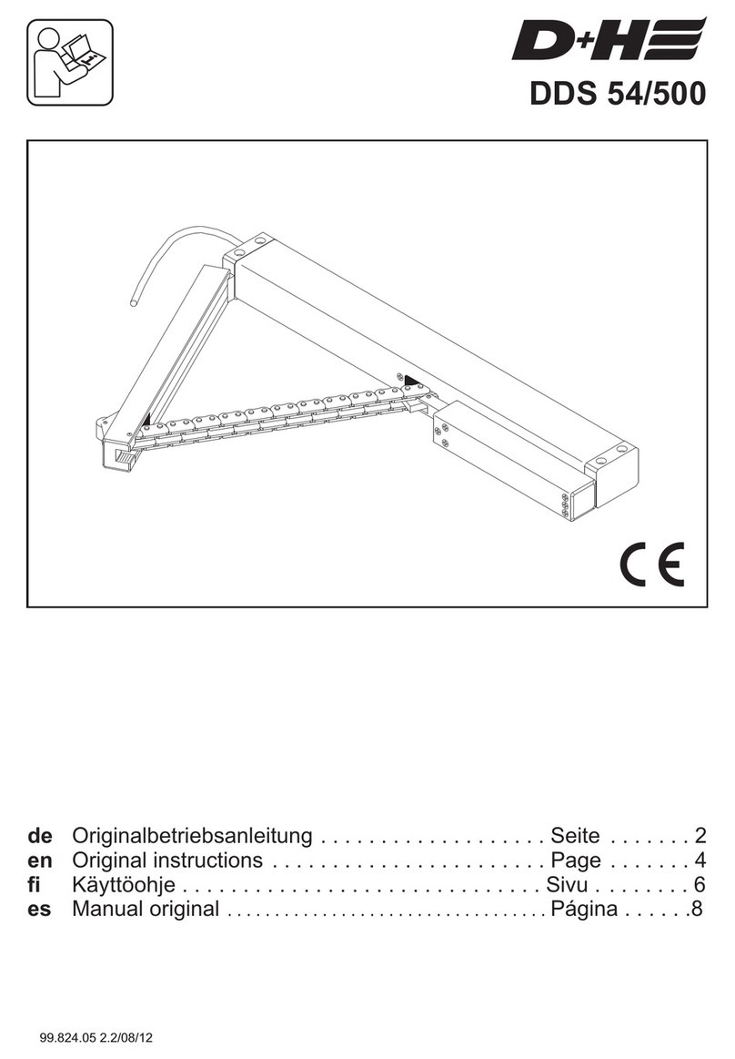
D+H DDS 54/500 User manual

D+H

D+H DDS 54/500 User manual

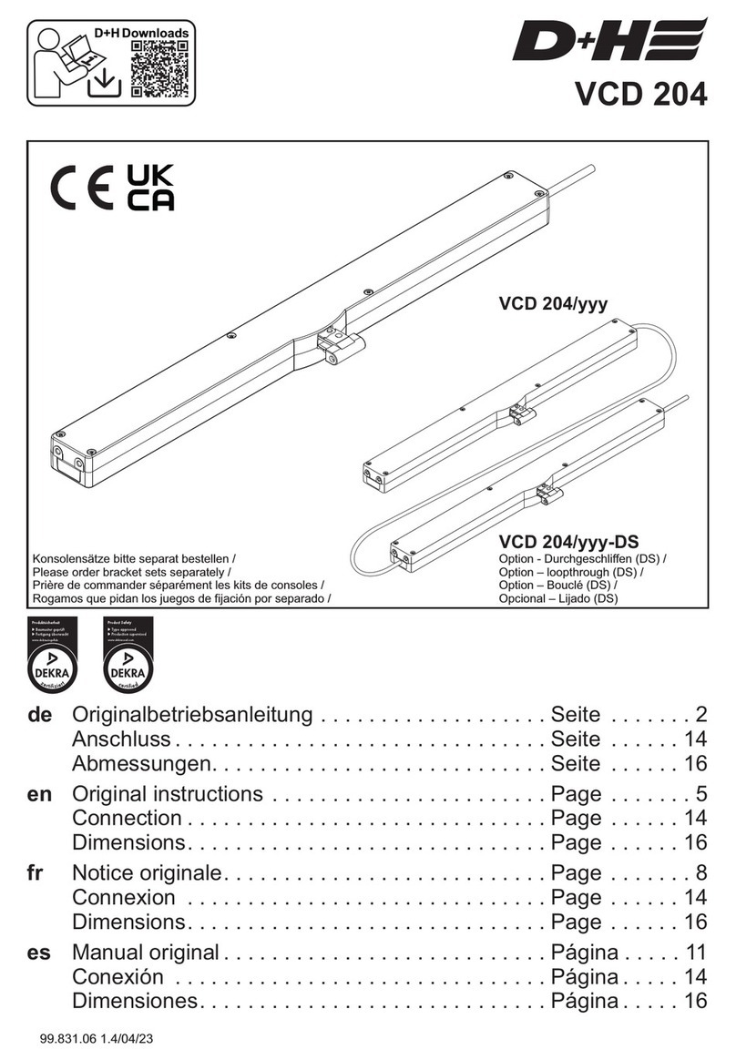
D+H VCD 204 User manual

D+H

D+H VCD 204 User manual

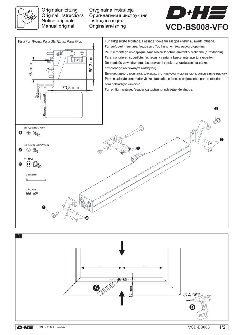
D+H VCD-BS008-VFO User manual

D+H

D+H VCD-BS008-VFO User manual

D+H CDC-BS022 User manual

D+H

D+H CDC-BS022 User manual

D+H KA 66-TW1-K-BSY+ User manual

D+H

D+H KA 66-TW1-K-BSY+ User manual

D+H ZA 35-BSY+(-HS) User manual

D+H

D+H ZA 35-BSY+(-HS) User manual

D+H ZA35-BSY+(-HS) User manual

D+H

D+H ZA35-BSY+(-HS) User manual

D+H VCD 204 User manual

D+H

D+H VCD 204 User manual

D+H VCD 203 User manual

D+H

D+H VCD 203 User manual

D+H VCD-BS001-VSI User manual

D+H

D+H VCD-BS001-VSI User manual

D+H ZA 35-HS User manual

D+H

D+H ZA 35-HS User manual

D+H KA 34-K-BSY Plus User manual

D+H

D+H KA 34-K-BSY Plus User manual

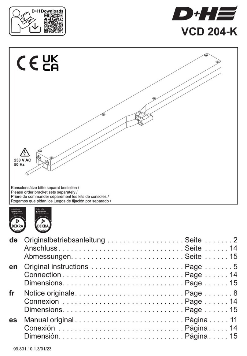
D+H VCD 204-K User manual

D+H

D+H VCD 204-K User manual

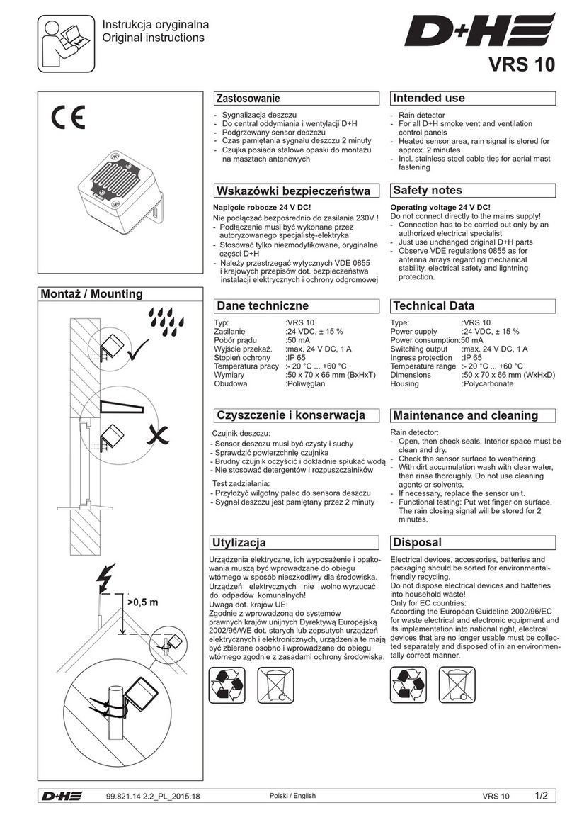
D+H VRS 10 User manual

D+H

D+H VRS 10 User manual

D+H KA 34-K User manual

D+H

D+H KA 34-K User manual

D+H BAZ 04-N-UT User manual

D+H

D+H BAZ 04-N-UT User manual

Popular Door Opening System manuals by other brands

Dormakaba ED 250 LE user manual

Dormakaba

Dormakaba ED 250 LE user manual

Dictator DICTAMAT 900-21 Technical manual

Dictator

Dictator DICTAMAT 900-21 Technical manual

Dorma 7400 DS manual

Dorma

Dorma 7400 DS manual

Henderson HUSKY Folding 25 Series Fitting instructions

Henderson

Henderson HUSKY Folding 25 Series Fitting instructions

Lamp Lapcon J160 installation instructions

Lamp

Lamp Lapcon J160 installation instructions

S4A RS-140 quick start guide

S4A

S4A RS-140 quick start guide

Yale YM Series installation instructions

Yale

Yale YM Series installation instructions

DEUTSCHTEC SLH Series installation manual

DEUTSCHTEC

DEUTSCHTEC SLH Series installation manual

GAL MOM How to connect

GAL

GAL MOM How to connect

Portalp SW10 installation guide

Portalp

Portalp SW10 installation guide

Dormakaba ED250 installation instructions

Dormakaba

Dormakaba ED250 installation instructions

Micom 2ES ALE instruction manual

Micom

Micom 2ES ALE instruction manual

Dorma AS 350 installation manual

Dorma

Dorma AS 350 installation manual

DoorHan DH1500 user manual

DoorHan

DoorHan DH1500 user manual

Brookfield Industries NB-500 manual

Brookfield Industries

Brookfield Industries NB-500 manual

Automatic Technology DOMINATOR ShedMaster GDO-8V3 instruction manual

Automatic Technology

Automatic Technology DOMINATOR ShedMaster GDO-8V3 instruction manual

Yale 3040 installation instructions

Yale

Yale 3040 installation instructions

LCN 3130 Series installation instructions

LCN

LCN 3130 Series installation instructions

manuals.online logo
manuals.online logoBrands
  • About & Mission
  • Contact us
  • Privacy Policy
  • Terms and Conditions

Copyright 2025 Manuals.Online. All Rights Reserved.