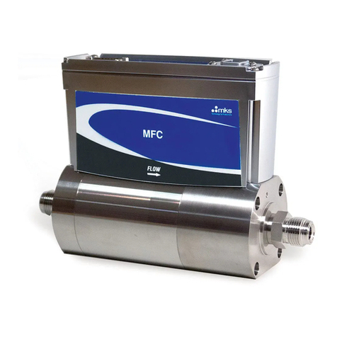
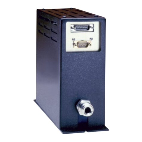
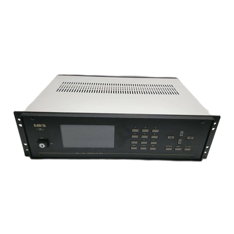
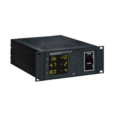
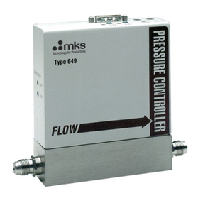
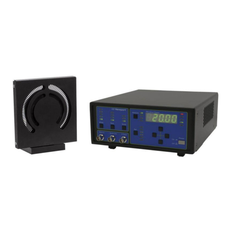
MKS 651C User manual

115605-P1
Rev F, 10/97
Instruction Manual
MKS Type 651C
Pressure Controller
Six Shattuck Road
Andover, MA 01810-2449
(800) 227-8766 or (978) 975-2350
Fax: (978) 975-0093
E-mail: mks@mksinst.com
Web site: http://www.mksinst.com

WARRANTY
Type 651C Equipment
MKS Instruments, Inc. (MKS) warrants that the equipment described above (the
“equipment”) manufactured by MKS shall be free from defects in materials and
workmanship for a period of one year from date of shipment and will for a period of two
years from the date of shipment, correctly perform all date-related operations, including
without limitation accepting data entry, sequencing, sorting, comparing, and reporting,
regardless of the date the operation is performed or the date involved in the operation,
provided that, if the equipment exchanges data or is otherwise used with equipment,
software, or other products of others, such products of others themselves correctly
perform all date-related operations and store and transmit dates and date-related data
in a format compatible with MKS equipment. THIS WARRANTY IS MKS’ SOLE
WARRANTY CONCERNING DATE-RELATED OPERATIONS.
For the period commencing with the date of shipment of this equipment and ending one
year later in the case of defects in materials and workmanship, but two years later in the
case of failure to comply with the date-related operations warranty, MKS will, at its
option, either repair or replace any part which is defective in materials or workmanship
or with respect to the date-related operations warranty without charge to the purchaser.
The foregoing shall constitute the exclusive and sole remedy of the purchaser for any
breach by MKS of this warranty.
The purchaser, before returning any equipment covered by this warranty, which is
asserted to be defective by the purchaser, shall make specific written arrangements
with respect to the responsibility for shipping the equipment and handling any other
incidental charges with the MKS sales representative or distributor from which the
equipment was purchased or, in the case of a direct purchase from MKS, with the MKS
home office in Andover, Massachusetts, USA.
This warranty does not apply to any equipment which has not been installed and used
in accordance with the specifications recommended by MKS for the proper and normal
use of the equipment. MKS shall not be liable under any circumstances for indirect,
special, consequential, or incidental damages in connection with, or arising out of, the
sale, performance, or use of the equipment covered by this warranty.
MKS recommends that all MKS pressure and flow products be calibrated periodically
(typically every 6 to 12 months) to ensure accurate readings. When a product is
returned to MKS for this periodic re-calibration it is considered normal preventative
maintenance not covered by any warranty.
THIS WARRANTY IS IN LIEU OF ALL OTHER RELEVANT WARRANTIES,
EXPRESSED OR IMPLIED, INCLUDING THE IMPLIED WARRANTY OF
MERCHANTABILITY AND THE IMPLIED WARRANTY OF FITNESS FOR A
PARTICULAR PURPOSE, AND ANY WARRANTY AGAINST INFRINGEMENT OF
ANY PATENT.
11-98 115605-P1

115605-P1

Rev F, 10/97
MKS Type 651C
Pressure Controller
Set
Point
A
B
C
Stop
Open
Close
Learn
Zero
Select Ad
j
ust
600 Series
Pressure Controller
Valve
Local
Remote
Parameters
D
E

Copyright © 1997 by MKS Instruments, Inc.
All rights reserved. No part of this work may be reproduced or transmitted in any form or by
any means, electronic or mechanical, including photocopying and recording, or by any
information storage or retrieval system, except as may be expressly permitted in writing by MKS
Instruments, Inc.
Baratron®is a registered trademark of MKS Instruments, Inc., Andover, MA
This manual is for firmware version 1.8x
Please Note:
MKS Instruments provides these documents as the latest version for the revision indicated.
The material is subject to change without notice, and should be verified if used in a critical
application.

Table of Contents
iii
Table of Contents
Safety Information.................................................................................................................. 1
Symbols Used in This Instruction Manual.................................................................. 1
Symbols Found on the Unit ....................................................................................... 2
Safety Procedures and Precautions............................................................................. 3
Sicherheitshinweise................................................................................................................ 5
In dieser Betriebsanleitung vorkommende Symbole................................................... 5
Am Gerät angebrachte Symbole................................................................................. 6
Sicherheitsvorschriften und Vorsichtsmaßnahmen...................................................... 7
Informations relatives àla sécurité.......................................................................................... 9
Symboles utilisés dans ce manuel d'utilisation ........................................................... 9
Symboles apparaissant sur l'appareil .......................................................................... 10
Mesures de sécuritéet mises en garde........................................................................ 11
Información sobre seguridad................................................................................................... 13
Símbolos usados en el manual de instrucciones.......................................................... 13
Símbolos que aparecen en la unidad........................................................................... 14
Procedimientos y precauciones de seguridad.............................................................. 15
Chapter One: General Information......................................................................................... 17
Introduction............................................................................................................... 17
How This Manual is Organized.................................................................................. 18
Customer Support...................................................................................................... 19
Chapter Two: Installation......................................................................................................21
How To Unpack the Type 651 Unit ........................................................................... 21
Unpacking Checklist.................................................................................................. 21
Product Location and Requirements........................................................................... 22
Operating Environmental Requirements ........................................................ 22
Safety Conditions.......................................................................................... 22
Setup ......................................................................................................................... 23
Environmental Requirements......................................................................... 23

Table of Contents
iv
Checking the Fuses and Line Voltage Selector Switch...................................24
How To Change the Line Voltage..................................................................25
Chapter Three: Overview.......................................................................................................27
Front Panel.................................................................................................................27
Front Panel Components................................................................................27
Front Panel Display.......................................................................................28
Local and Remote Operation..........................................................................29
Command Priority .........................................................................................29
Control Mode: Self-Tuning or PID Control...................................................29
Softstart Control ............................................................................................30
Battery Backups.............................................................................................30
Rear Panel..................................................................................................................31
Rear Panel Components.................................................................................31
Electrical Connections ...................................................................................32
Labels ........................................................................................................................38
Serial Number Label......................................................................................38
Chapter Four: System Setup...................................................................................................39
Overview....................................................................................................................39
RS-232 Commands and Requests ..................................................................39
Valve Selection and Calibration.....................................................................40
Setup Menu................................................................................................................41
Control Mode ................................................................................................41
RS-232 Communications...............................................................................42
Sensor Setup..................................................................................................43
Analog Set Point............................................................................................45
Valve Position Output....................................................................................45
Set Points A Through E, Pressure/Position Selection .....................................46
Softstart Rates................................................................................................47
Valve Control................................................................................................48
Chapter Five: Local Operation...............................................................................................49
Overview....................................................................................................................49
How To View and Adjust Set Points..........................................................................50

Table of Contents
v
How To Activate Set Points....................................................................................... 51
How To Identify an Out-of-Range Condition............................................................. 51
How To Control the Valve......................................................................................... 52
How To Open the Valve................................................................................ 52
How To Close the Valve ............................................................................... 52
How To Halt the Valve.................................................................................. 52
How To Activate the Learn Function......................................................................... 53
How To Stop the Learn Function................................................................... 53
How To Zero a Sensor............................................................................................... 54
How To Use Special Zero.............................................................................. 54
How To Remove Zero................................................................................... 54
How To Set a Process Limit Relay............................................................................. 55
How To View and Adjust a Process Limit Relay........................................... 55
How To Disable a Process Limit Relay ......................................................... 55
How To View and Adjust the Analog Set Point ......................................................... 56
How To Zero the Analog Set Point................................................................ 56
How To Calibrate Full Scale Span for the Analog Set Point.......................... 57
How To Set Lead and Gain Parameters...................................................................... 58
How To Calibrate Span of the A/D Converter............................................................ 59
Chapter Six: Remote Operation............................................................................................. 61
Overview................................................................................................................... 61
RS-232 Commands and Requests .............................................................................. 61
Message Syntax............................................................................................. 61
Priority of Command Execution.................................................................... 63
How To Change Valve Selection and Calibration....................................................... 64
How To Determine and Change the Control Mode..................................................... 65
How To Configure the Sensor Parameters.................................................................. 66
How To Change the Sensor Type.................................................................. 66
How To Change the Sensor Full Scale Voltage.............................................. 66
How To Change the Sensor Range ................................................................ 67
How To Request the Pressure Reading....................................................................... 68
Converting Pressure Readings to Absolute Pressure Values........................... 68
How To Zero a Sensor............................................................................................... 69

Table of Contents
vi
How To Use the Special Zero ........................................................................69
How To Remove the Zero..............................................................................69
How To Activate the Learn Function..........................................................................70
How To Stop the Learn Function...................................................................71
How To Determine the Active Set Point.....................................................................72
How To Select the Active Set Point............................................................................73
How To Select Pressure or Position Control...............................................................74
How To Change the Set Point Value ..........................................................................75
How To Adjust the Analog Set Point Value................................................................76
How To Set the Analog Set Point Full Scale Range.......................................76
How To Zero the Analog Set Point................................................................77
How To Learn Analog Set Point Full Scale....................................................77
How To Set the Full Scale Level of the Analog Set Point ..............................78
How To Calibrate Span of the A/D Converter.............................................................79
How To Respond To a Checksum Error .....................................................................80
How To Set the Lead and Gain Parameters.................................................................81
How To Set The Softstart Control Rate......................................................................83
How To Set the Softstart Rate........................................................................83
How To Use the Softstart Rate.......................................................................83
How To Check the Softstart Rate...................................................................84
How To Configure the Valve Parameters....................................................................85
How To Check the Valve Selected.................................................................85
How To Change and Calibrate the Valve .......................................................85
How To Change the Valve Position Output....................................................86
How To Change the Valve Control Direction.................................................86
How To Control the Valve .........................................................................................87
How To Open the Valve ................................................................................87
How To Close the Valve................................................................................87
How To Halt the Valve..................................................................................87
How To Set a Process Limit Relay.............................................................................88
How To View and Adjust a Process Limit Relay............................................88
How To Disable a Process Limit Relay..........................................................88
How To Check the System Status...............................................................................89

Table of Contents
vii
How To Check the Firmware Version........................................................................ 89
Digital Logic Control................................................................................................. 90
I/O Board Digital Circuitry............................................................................ 90
Digital Input Priorities................................................................................... 92
Digital Functions........................................................................................... 93
Analog Set Point Inputs................................................................................. 95
Chapter Seven: Battery-Backed Memory Module.................................................................. 97
Replacing the Battery-Backed Memory Module......................................................... 97
Opening the Unit........................................................................................... 97
Removing the CPU Board and Memory Module ........................................... 98
Installing a New Memory Module and Replacing the CPU Board.................. 99
Replacing the Cover...................................................................................... 99
Chapter Eight: Valve Failsafe Battery Back-up Option.......................................................... 101
General Information................................................................................................... 101
Battery Voltage.......................................................................................................... 102
Valve Positions.......................................................................................................... 102
Startup....................................................................................................................... 103
Threshold Voltage Check .............................................................................. 103
Battery Voltage Within Range....................................................................... 103
Battery Voltage Out-of-Range....................................................................... 104
Operation................................................................................................................... 105
How To Check the Battery Voltage............................................................... 105
How To Set The Battery Back-up Valve Control........................................... 106
Expected Battery Life................................................................................................ 108
Battery Storage.......................................................................................................... 108
Battery Replacement.................................................................................................. 109
Opening the Unit........................................................................................... 109
Installing the New Battery............................................................................. 110
Chapter Nine: Maintenance ................................................................................................... 111
General Information................................................................................................... 111
How To Replace Fuses .............................................................................................. 111
Appendix A: Product Specifications...................................................................................... 113

Table of Contents
viii
Appendix B: Model Code Explanation...................................................................................115
Model Code ...............................................................................................................115
Appendix C: Product Compatibility.......................................................................................117
Product Compatibility................................................................................................117
Valves ...........................................................................................................117
Transducers ...................................................................................................117
Adapter Cables ..............................................................................................118
Appendix D: Type 651 Displayless Unit................................................................................119
Type 651 Displayless Unit .........................................................................................119
RS-232 Configuration ................................................................................................120
Internal Switches ...........................................................................................120
Opening/Closing the 651 Controller...............................................................120
Dipswitch Bank Settings................................................................................122
Appendix E: Initial Settings...................................................................................................125
Appendix F: Command and Request Reference......................................................................127
Command Reference..................................................................................................127
Request and Response Reference................................................................................134
Index ......................................................................................................................................141

List of Figures
ix
List of Figures
Figure 1: Voltage and Fuse Data for the Low Power Unit...................................................... 25
Figure 2: Voltage and Fuse Data for the High Power Unit..................................................... 26
Figure 3: Front Panel of the 651 Instrument........................................................................... 27
Figure 4: Rear Panel of the 651 Instrument............................................................................ 31
Figure 5: Serial Number Label .............................................................................................. 38
Figure 6: I/O Board Digital Input Circuitry............................................................................ 90
Figure 7: I/O Board Digital Output Circuitry......................................................................... 91
Figure 8: Location of the Battery-backed RAM Module........................................................ 98
Figure 9: Initial Display Screen............................................................................................. 103
Figure 10: Default Pressure and Position Screen.................................................................... 103
Figure 11: Battery Voltage Low Message.............................................................................. 104
Figure 12: Battery Voltage High Message............................................................................. 104
Figure 13: Fuse Holder.......................................................................................................... 112
Figure 14: Front Panel of the 651 Displayless Unit................................................................ 119
Figure 15: Dipswitch Bank Location (Top View) .................................................................. 121
Figure 16: Example of Dipswitch Bank................................................................................. 121

List of Figures
x

List of Tables
xi
List of Tables
Table 1: Definition of Symbols Found on the Unit .....................................................................2
Tabelle 2: Definitionen der am Gerät angebrachten Symbole.......................................................6
Tableau 3 : Définition des symboles apparaissant sur l'appareil .................................................10
Tabla 4 : Definición de los símbolos que aparecen en la unidad.................................................14
Table 5: Fuse Information ........................................................................................................24
Table 6: Summary of Front Panel Components.........................................................................28
Table 7: Slot Labels .................................................................................................................31
Table 8: Serial RS-232 Interface Connector Pinout...................................................................32
Table 9: RS-232 Serial Communication Cables........................................................................33
Table 10: I/O Connector Pinout................................................................................................34
Table 11: Transducer Connector Pinout....................................................................................36
Table 12: System Interface Cables for MKS Transducers .........................................................36
Table 13: Valve Connector Pinout............................................................................................37
Table 14: System Interface Cables for MKS Throttle Valves....................................................37
Table 15: Sensor Range Values................................................................................................67
Table 16: Priority of Digital Inputs...........................................................................................92
Table 17: Digital Input Functions..............................................................................................93
Table 18: Digital Output Functions ..........................................................................................95
Table 19: Expected Battery Life.............................................................................................108
Table 20: Capacity Loss of Stored Battery..............................................................................108
Table 21: Transducer Current Available from Low and High Power Units..............................117
Table 22: 651 Adapter Cables.................................................................................................118
Table 23: Default Dipswitch Settings .....................................................................................122
Table 24: I/O Board Dipswitch Bank and RS-232 Communications Settings..........................123
Table 25: Initial Settings ........................................................................................................125
Table 26: RS-232 Command Summary ..................................................................................128
Table 27: RS-232 Request and Response Summary................................................................134

List of Tables
xii

Safety Information S
y
mbols Used in This Instruction Manual
1
Safety Information
Symbols Used in This Instruction Manual
Definitions of WARNING, CAUTION, and NOTE messages used throughout the manual.
Warning The WARNING sign denotes a hazard. It calls attention to a
procedure, practice, condition, or the like, which, if not
correctly performed or adhered to, could result in injury to
personnel.
Caution The CAUTION sign denotes a hazard. It calls attention to an
operating procedure, practice, or the like, which, if not correctly
performed or adhered to, could result in damage to or destruction of
all or part of the product.
Note The NOTE sign denotes important information. It calls attention to a
procedure, practice, condition, or the like, which is essential to highlight.

Symbols Found on the Unit Safet
y
Information
2
Symbols Found on the Unit
The following table describes symbols that may be found on the unit.
Definition of Symbols Found on the Unit
|
On (Supply)
IEC 417, No.5007 Off (Supply)
IEC 417, No.5008 Earth (
g
round)
IEC 417, No.5017
Protective earth
(
g
round)
IEC 417, No.5019
Frame or chassis
IEC 417, No.5020 Equipotentiality
IEC 417, No.5021 Direct current
IEC 417, No.5031 Alternatin
g
current
IEC 417, No.5032
Both direct and
alternatin
g
current
IEC 417, No.5033-a Class ll equipment
IEC 417, No.5172-a
Three phase
alternatin
g
current
IEC 617-2 No.020206
Caution, refer to
accompanyin
g
documents
ISO 3864, No.B.3.1
Caution, risk of
electric shock
ISO 3864, No.B.3.6 Caution, hot surface
IEC 417, No.5041
Table 1: Definition of Symbols Found on the Unit

Safety Information Safet
y
Procedures and Precautions
3
Safety Procedures and Precautions
The following general safety precautions must be observed during all phases of operation of this
instrument. Failure to comply with these precautions or with specific warnings elsewhere in
this manual violates safety standards of intended use of the instrument and may impair the
protection provided by the equipment. MKS Instruments, Inc. assumes no liability for the
customer’s failure to comply with these requirements.
DO NOT SUBSTITUTE PARTS OR MODIFY INSTRUMENT
Do not install substitute parts or perform any unauthorized modification to the instrument.
Return the instrument to an MKS Calibration and Service Center for service and repair to ensure
that all safety features are maintained.
SERVICE BY QUALIFIED PERSONNEL ONLY
Operating personnel must not remove instrument covers. Component replacement and internal
adjustments must be made by qualified service personnel only.
GROUNDING THE PRODUCT
This product is grounded through the grounding conductor of the power cord. To avoid electrical
shock, plug the power cord into a properly wired receptacle before connecting it to the product
input or output terminals. A protective ground connection by way of the grounding conductor in
the power cord is essential for safe operation.
DANGER ARISING FROM LOSS OF GROUND
Upon loss of the protective-ground connection, all accessible conductive parts (including knobs
and controls that may appear to be insulating) can render an electrical shock.
GROUND AND USE PROPER ELECTRICAL FITTINGS
Dangerous voltages are contained within this instrument. All electrical fittings and cables must
be of the type specified, and in good condition. All electrical fittings must be properly connected
and grounded.
USE THE PROPER POWER CORD
Use only a power cord that is in good condition and which meets the input power requirements
specified in the manual.
Use only a detachable cord set with conductors that have a cross-sectional area equal to or greater
than 0.75 mm2. The power cable should be approved by a qualified agency such as VDE,
Semko, or SEV.

Safety Procedures and Precautions Safet
y
Information
4
USE THE PROPER POWER SOURCE
This product is intended to operate from a power source that does not apply more voltage
between the supply conductors, or between either of the supply conductors and ground, than that
specified in the manual.
USE THE PROPER FUSE
Use only a fuse of the correct type, voltage rating, and current rating, as specified for your
product.
DO NOT OPERATE IN EXPLOSIVE ATMOSPHERES
To avoid explosion, do not operate this product in an explosive environment unless it has been
specifically certified for such operation.
HIGH VOLTAGE DANGER
High voltage is present in the cable, and in the sensor when the controller is turned on.

Sicherheitshinweise In dieser Betriebsanleitun
g
vorkommende S
y
mbole
5
Sicherheitshinweise
In dieser Betriebsanleitung vorkommende Symbole
Definition der mit WARNUNG!, VORSICHT! und HINWEIS überschriebenen Abschnitte in
dieser Betriebsanleitung.
Warnung!
&CU 5[ODQN 9#4070) YGKUV CWH GKPG )GHCJTGPSWGNNG JKP 'U
OCEJV CWH GKPGP #TDGKVUCDNCWH GKPG #TDGKVUYGKUG GKPGP
<WUVCPF QFGT GKPG UQPUVKIG )GIGDGPJGKV CWHOGTMUCO FGTGP
WPUCEJIGO·G #WUHÒJTWPI D\Y WPIGPÒIGPFG
$GTÒEMUKEJVKIWPI \W -ÌTRGTXGTNGV\WPI HÒJTGP MCPP
8QTUKEJV
Das Symbol VORSICHT! weist auf eine Gefahrenquelle hin. Es
macht auf einen Bedienungsablauf, eine Arbeitsweise oder eine
sonstige Gegebenheit aufmerksam, deren unsachgemäße Ausführung
bzw. Ungenügende Berücksichtigung zu einer Beschädigung oder
Zerstörung des Produkts oder von Teilen des Produkts führen kann.
*KPYGKU
Das Symbol HINWEIS weist auf eine wichtige Mitteilung hin, die auf
einen Arbeitsablauf, eine Arbeitsweise, einen Zustand oder eine sonstige
Gegebenheit von besonderer Wichtigkeit aufmerksam macht.

Am Gerät angebrachte Symbole Sicherheitshinweise
6
Am Gerät angebrachte Symbole
Der untenstehenden Tabelle sind die Bedeutungen der Symbole zu entnehmen, die an dem Gerät
angebracht sind.
Definitionen der am Gerät angebrachten Symbole
|
Ein (Netz)
IEC 417, Nr. 5007 Aus (Netz)
IEC 417, Nr. 5008 Erde
IEC 417, Nr. 5017 Schutzleiter
IEC 417, Nr. 5019
Rahmen oder Chassis
IEC 417, Nr. 5020 Äquipotentialanschluß
IEC 417, Nr. 5021 Gleichstrom
IEC 417, Nr. 5031 Wechselstrom
IEC 417, Nr. 5032
Wechselstrom und
Gleichstrom
IEC 417, Nr. 5033-a Geräteklasse II
IEC 417, Nr. 5172-a Drehstrom
IEC 617-2 Nr. 020206
Vorsicht! Bitte
Begleitdokumente
lesen!
ISO 3864, Nr. B.3.1
Vorsicht!
Stromschlaggefahr!
ISO 3864, Nr. B.3.6
Vorsicht!
Heiße Fläche!
IEC 417, Nr. 5041
Tabelle 2: Definitionen der am Gerät angebrachten Symbole
Table of contents
Other MKS Controllers manuals
Popular Controllers manuals by other brands

Altronix
Altronix MAXIMAL FIT MaxFit3F5AP installation guide

Sealey
Sealey SA4FR/38 instructions

Flex-a-Lite
Flex-a-Lite 31165 installation instructions

Bromic Heating
Bromic Heating Smart-Heat BH3130011-2 user manual

Siemens
Siemens Powermite 599 MT Series Technical instructions

Danfoss
Danfoss AME 140X operating guide