manuals.online logo
Brands
  1. Home
  2. •
  3. Brands
  4. •
  5. Draper
  6. •
  7. Projection Screen
  8. •
  9. Draper Clarion User manual

Draper Clarion User manual

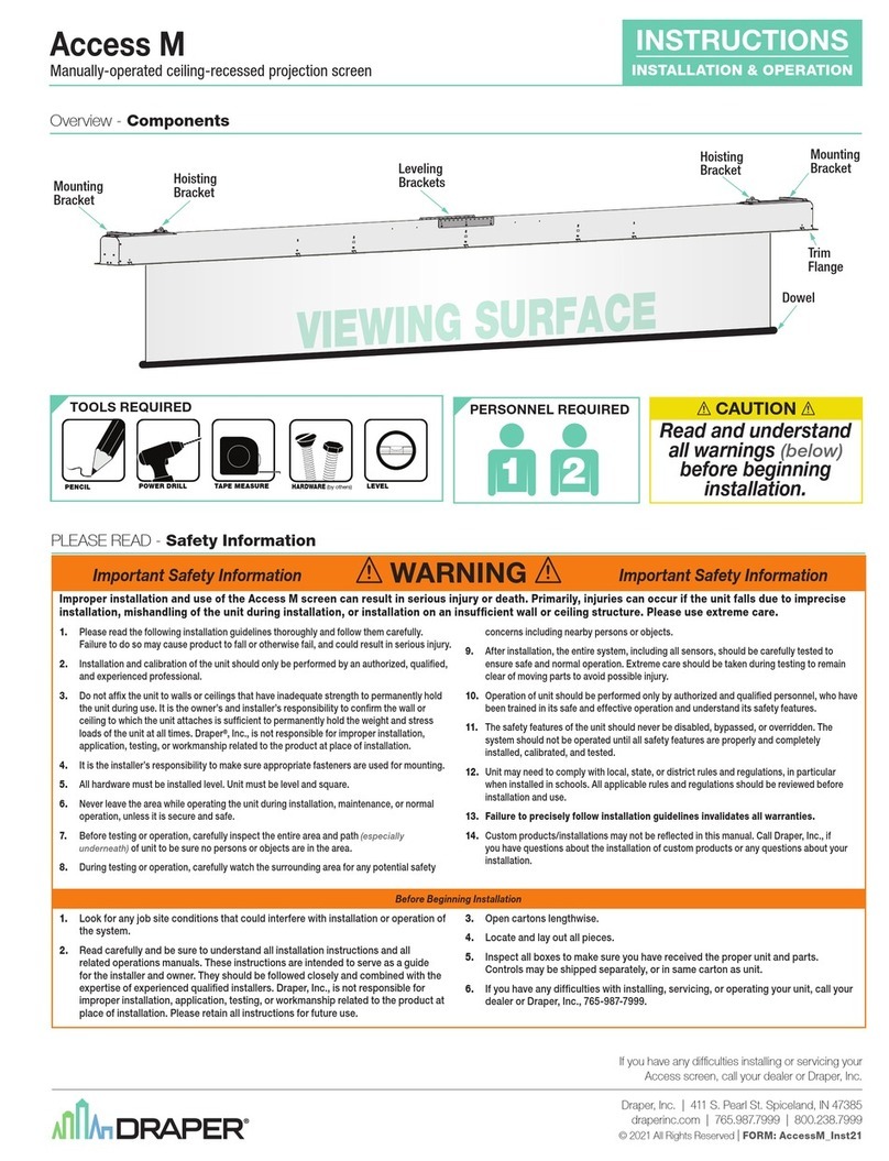
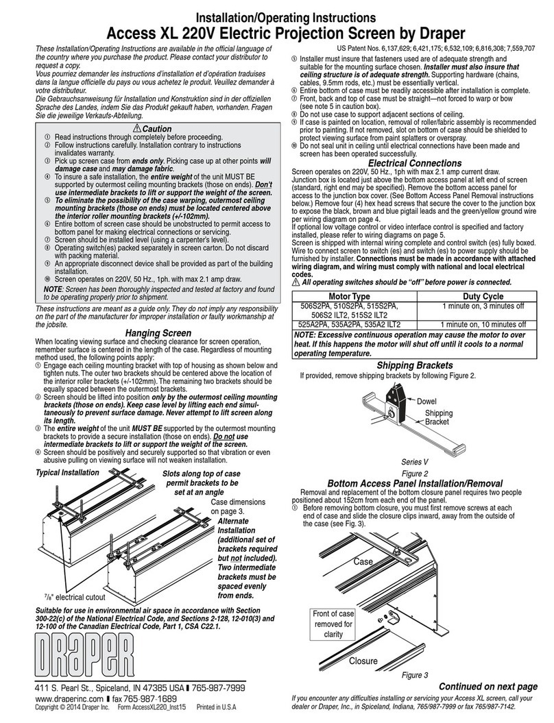
Assembly/Mounting Instructions
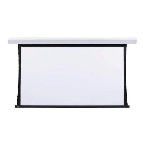
Clarion Permanently Tensioned Projection Screen by Draper
# 6 x 1
Pan Head
Screw
#8 x 3/8"
Pan Head
Screw
Corner Gusset
#8 x 3/8"
Pan Head
Screw Audience
Side
Slot Receives Screw
Base
Frame
#10-24 x 1/2"
Flat Head
Screw
See detail for
configuration
possibilities
Trim Frame
Audience
Side
Caution
➀Read instructions through completely before proceeding.
➁Follow instructions carefully. Installation contrary to instructions
invalidates warranty.
➂Screen should be accessible for complete removal should fabric
become damaged or should other service be required.
➃Screen should be installed level (using a carpenter’s level).
➄Nothing should be fastened to screen frame or viewing surface.
➅Operating switch(es), for electric tilting screens, packed separately in
screen carton. Do not discard with packing material.
➆Electric tilting mechanism operates on 110-120v, 60 hz. current.
➇Tools Required: Medium (#2) Phillips Screwdriver, Carpenters Level,
Soft face (rubber) Hammer & Measuring Tape.
NOTE: Screen has been thoroughly inspected and tested at factory and
found to be operating properly prior to shipment.
Assembly of “Knocked-Down” Screen
General—
Assemble inner frame on large table or on floor. Refer to the exploded
drawing on page 3 as you read these instructions.
Open cartons along the length, not at ends. Remove all pieces from the
carton. Lay out the four sections of the inner frame (top, bottom, left and right)
with the front sides facing up. (Back of frame is side with snaps.)
Screw the left and right sides to the top and bottom frame members using the
#6 x 1" screws through the two pre-drilled holes in each end of sides. Screws
should thread into the circular screw channels. Make sure frame assembly is
square by measuring across frame diagonals.
Place and screw one corner gusset to the inner frame assembly at each
corner with (6) #8 x
3
/
8
" pan head screws. Screws pass through pre-punched
holes in gussets and thread into screw channel on inner frame.
Connect horizontal brace and vertical brace using (2) #10 x
1
/
2
" screws. See
page 4 for the various configurations.
Place bracing assembly inside the inner frame so the plates at each end of
braces are completely visible from the front. Make sure these braces are
perpendicular to the inner frame sections. Insert #8 x
3
/
8
" screws through the
holes in these plates and into the screw channel on the inner frame. The inner
frame assembly is now complete.
Align and start engagement of bracket in the side trim with slot in top trim by
hand. Use rubber hammer to drive trims fully together. Repeat for the other
corners of screen.
Attachment of Viewing Surface
Two people should attach the viewing surface of large screens, to
prevent possible damage.
Unroll the viewing surface from the core with the viewing side face down. Be
extremely careful to protect the viewing surface by unrolling it onto a clean
cloth or paper.
Place the inner frame assembly,
with front side down
, against the back of
the viewing surface. Make sure the top piece of frame corresponds with the
top side of the viewing surface.
Pull border snaps on viewing surface around the inner frame and snap to the
back side of the frame. Engage the 2 snaps at each corner first, then go along
each side and engage the remaining snaps.
Pivot the frame/fabric assembly up into a vertical position and inspect surface.
Lay frame/fabric assembly with viewing surface up. Frame is ready for
installation of trim frames.
Place the four trim sections next to the correct sides of the frame/fabric
assembly. The side trim sections will have connecting brackets located in
each end. These brackets will align and hold the face of the trim sections
together. Place the top and bottom trims over the top and bottom of the frame/
fabric assembly. (Do not slide the trim sections along the outside edges
of the frame/fabric assembly. Doing this could damage the fabric
viewing surface.)
Copyright © 2002 Draper Inc. Form Clarion_Inst02 Printed in U.S.A.
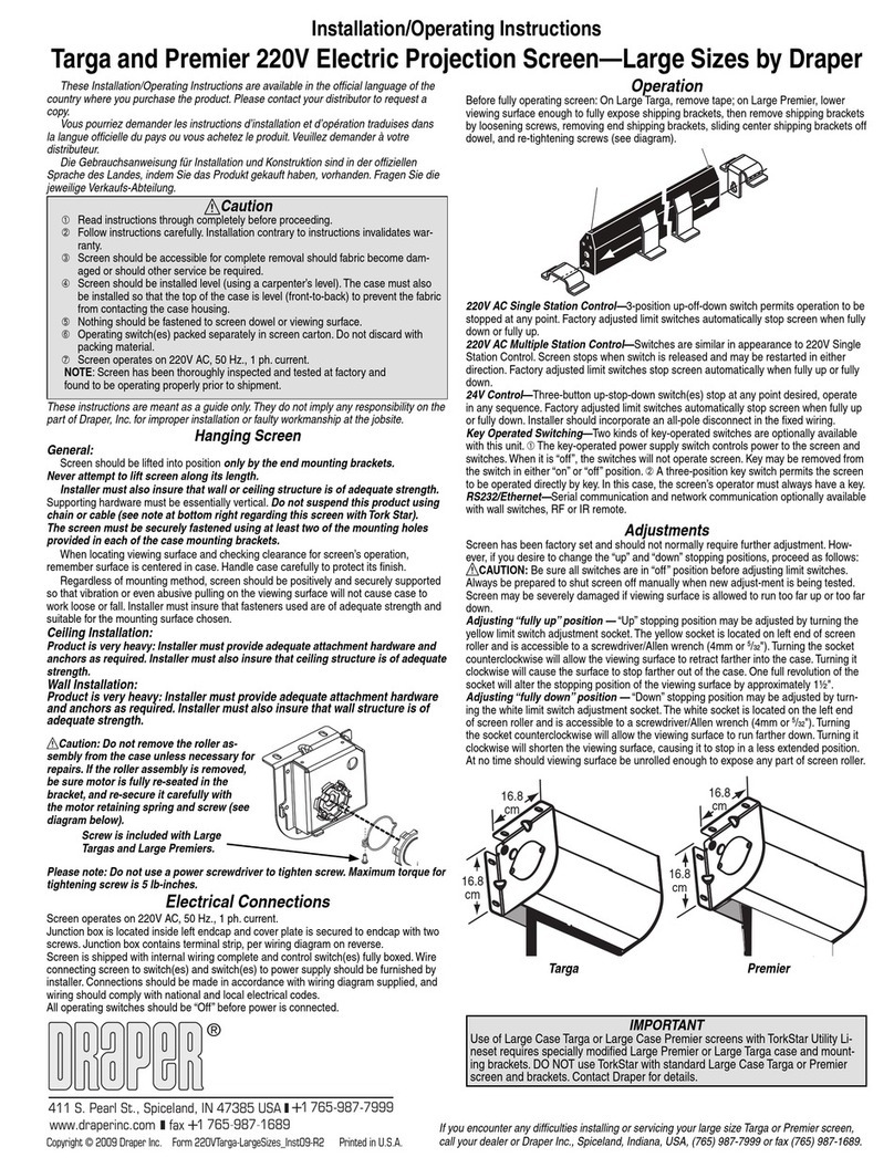
Trim Frame
Base Frame
Audience
Side
Slot Receives Screw
#8 x 32
Pan Head
Screw
Trim Frame has lip on rear side
Wall Mounting Brackets
Viewing Surface
After all four corners of trims are connected, turn entire screen assembly over
so viewing surface is face down. Be sure to protect surface in this position.
The trims must be fastened to the inner frame with #8 x
3
/
8
" screws. Each trim
has predrilled holes in the back flange. Start by screwing the corners together
first. It may be necessary to squeeze the trims together at corners to close any
gaps. Do this before screwing trim to inner frame. Finish attaching trims along
their length with additional screws.
Clarion by Draper Page 2 of 4
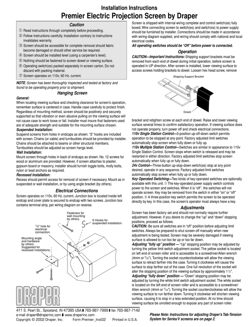
The screen frame is assembled and ready for fixed wall mounting or
attachment to tilting angles.
Wall Mounting of Fixed Frames
Mount 2, 3, or, 4 aluminum brackets provided on the wall at desired height.
Use carpenters level to ensure these brackets are level. When the screen is
mounted, the top of the frame will be
1
/
8
" above the top of these brackets. ¾"
of free space is required above these brackets. When the screen is set on the
mounting brackets, pull down gently to ensure that the engagement is snug
and secure.
The screen should be positively and securely supported so vibration or
abusive handling will not cause the screen to work loose or fall. The installer
must insure that the fasteners are of adequate strength and suitable for the
mounting surface chosen.
The center line of the gearbox should be mounted so the nylon tape runs
vertically up to the pulley bracket. The horizontal shaft of the crank handle
assembly is inserted into the side of the gearbox. Mount the crank handle
bracket so the horizontal shaft is level and allow
1
/
8
" between the side of the
gearbox and the end of the
1
/
2
" diameter shaft.
Installer must insure that fasteners used are of adequate strength and suitable
for the mounting surface chosen.
Unwind the nylon ribbon from the reel on the gearbox. Pass the end of the
ribbon up and over the pulley on the upper angle.
On the electric model the reel and ribbon are located on the motor shaft on
the lower angle. The ribbon passes over the pulley in the same manner as on
the manual model.
Note: On the electric model you will probably wish to install electrical
box in the wall, so it will be concealed behind the screen frame.
Attach screen frame to the underside of the lower angle with screws and
lockwashers through the hinge plates on the lower backside of screen frame.
Attach the safety chains from the upper angle to the brackets on the upper
backside of screen frame. Attach the end of the nylon ribbon to the center of
the top section of screen frame. (See attached detail drawing.)
Electrical Connections
Screen operates on 110-120v, 60 hertz current. Wall electrical box should be
installed so as to be concealed by the screen frame after installation. Screen
motor is provided with approximately 6 ft. of cord. Wire connecting screen to
switch(es) and switch(es) to power supply should be furnished by installer.
Connections should be made in accordance with attached wiring diagram and
wiring should comply with local and national electrical codes.
All operating switches should be “off” before power is connected!
Adjustments
Manual models — the maximum tilt is controlled by an internal stop in the
gearbox. Set this as follows before the screen frame is attached to lower
angle. Turn the crank handle in the direction that unwinds the nylon ribbon
from the reel. When the stop is reached, the gearbox will stop - DO NOT
FORCE IT. Leave enough ribbon off the reel to allow the frame to tilt 20°
maximum or less if desired. With screen in maximum tilt position, the nylon
ribbon should be taut and safety chains should be slack. The upper or
minimum tilt limit (0°) is obtained when the screen reaches the vertical
position. The operator should discontinue cranking at this point.
Electric models — the maximum tilt and vertical screen positions are both
controlled by the limit switches in the motor.
Run the motor until it stops automatically in the “up” position (approximately
vertical). Make sure the screen frame is not attached to either of the angles
and the strap(s) on the roller spool can rotate freely before running motor.
The strap(s) may then be unwrapped sufficiently to thread through the pulley
on the upper angle leaving approximately 3 inches exposed past the pulley.
Make sure the strap(s) do not twist along their length.
Mount screen frame per attached instructions and attach safety chains to
brackets on the top backside of the screen frame. The strap(s) can then be
woven through the slotted brackets attached to the frame in the stopped
position (which is nearly vertical).
The exact vertical stopping position can now be fine tuned. Knob #2 on the
motor may be turned counterclockwise in small increments until the desired
vertical position is reached, or by adjusting the strap(s) in slotted brackets.
After the vertical position is set, the maximum tilt position may be adjusted to
desired tilt (20° maximum). Turn knob #1 counterclockwise to increase the tilt
and clockwise to reduce the amount of tilt.
CAUTION: Be sure switches are “off” before making limit switch
adjustments. Always be ready to manually shut off screen when new
adjustments are being made. When properly adjusted, the nylon ribbon
should be taut and safety chains slack at maximum tilt.
Wall Mounting of Tilting Screens
All tilting screens (manual and electric) require the attachment of the lower
angle and upper angle on the wall at the desired heights. The bottom edge of
the lower angle is 1
3
/
16
" higher than the bottom edge of the screen frame. The
upper angle should be 1
3
/
8
" below the top edge of the screen frame.
Verify that both of these angles are level and that the upper angle is centered
above the lower angle.
The mounting angles should be securely and positively mounted so that
vibration or even abusive pulling will not cause the angles to work loose or fall.
On the manual tilting models there are two additional brackets that need to be
mounted to the wall, the gearbox bracket and the crank handle bracket. (See
attached detail drawing.)
System Components
See detail for
configuration
possibilities
Audience
Side
Corner Gusset
#8 x 3/8 Pan Head Screw
#10-24 Flat
Head Screw
#6 x 1 Pan
Head Screw
Wiring Diagrams for Optional Motorized Tilting System
Clarion by Draper Page 3 of 4
Single Station Control
Junction box at
left end of screen
Internal Screen Wiring
White (Common)
Black (Tilt)
Red (Retract)
Green (Ground)
Dashed wiring
by electrician
Control
switch
Single gang box by others
Min. 4" x 2 1/8" x 1 7/8" deep
Blue
Black
Red
Location of key
operated on-off
switch if furnished
To 110v Line
Multiple Station Control
Junction box at
left end of screen
Internal Screen Wiring
White (Common)
Black (Tilt)
Red (Retract)
Green (Ground)
Dashed wiring
by electrician
Red
Red
Black
Blue
Blue
Cap off with wire
nut and tape
Black
Red Blue
Black Single gang box by others
Min. 4" x 2 1/8" x 1 7/8" deep.
3 shown. More or less equally
feasible.
Location of key
operated on-off
switch if furnished
To 110v Line
Bracing Configurations
Note: Sizes smaller than those shown require no bracing.
Clarion by Draper Page 4 of 4

Other manuals for Clarion

4

Other Draper Projection Screen manuals

Draper Silhouette V series User manual

Draper

Draper Silhouette V series User manual

Draper VCB Silhouette E series User manual

Draper

Draper VCB Silhouette E series User manual

Draper Premier Series User manual

Draper

Draper Premier Series User manual

Draper Premier User manual

Draper

Draper Premier User manual

Draper 220V Envoy Manual

Draper

Draper 220V Envoy Manual

Draper Nocturne+E Programming manual

Draper

Draper Nocturne+E Programming manual

Draper Targa Manual

Draper

Draper Targa Manual

Draper Onyx User manual

Draper

Draper Onyx User manual

Draper Silhouette/Series V Manual

Draper

Draper Silhouette/Series V Manual

Draper Odin User manual

Draper

Draper Odin User manual

Draper Envoy Manual

Draper

Draper Envoy Manual

Draper Clarion User manual

Draper

Draper Clarion User manual

Draper Tabletop Projection Screen MicroScreen User manual

Draper

Draper Tabletop Projection Screen MicroScreen User manual

Draper Foundation User manual

Draper

Draper Foundation User manual

Draper 218031 User manual

Draper

Draper 218031 User manual

Draper Artisan Series Manual

Draper

Draper Artisan Series Manual

Draper M Series User manual

Draper

Draper M Series User manual

Draper Ambassador 220V Manual

Draper

Draper Ambassador 220V Manual

Draper Access User manual

Draper

Draper Access User manual

Draper Silhouette C Series Manual

Draper

Draper Silhouette C Series Manual

Draper Ultimate Access V Installation instructions

Draper

Draper Ultimate Access V Installation instructions

Draper MC1 User manual

Draper

Draper MC1 User manual

Draper Targa Manual

Draper

Draper Targa Manual

Draper Premier PRE-28 User manual

Draper

Draper Premier PRE-28 User manual

Popular Projection Screen manuals by other brands

Da-Lite PROFESSIONAL ELECTROL Instruction book

Da-Lite

Da-Lite PROFESSIONAL ELECTROL Instruction book

Elite Screens Elite Home 2 Series user guide

Elite Screens

Elite Screens Elite Home 2 Series user guide

Elite Screens TE100HC2 user guide

Elite Screens

Elite Screens TE100HC2 user guide

Chetco Digital Instruments vGauge G12A user manual

Chetco Digital Instruments

Chetco Digital Instruments vGauge G12A user manual

EPV PowerMax Series user guide

EPV

EPV PowerMax Series user guide

Da-Lite MULTI-MASK IMAGER Instruction book

Da-Lite

Da-Lite MULTI-MASK IMAGER Instruction book

Da-Lite IDEA Panoramic Instruction book

Da-Lite

Da-Lite IDEA Panoramic Instruction book

MAXHUB C86CA-LGA572D-M Service manual

MAXHUB

MAXHUB C86CA-LGA572D-M Service manual

ADEO SCREEN FRAMEPRO PSCHT0300 user manual

ADEO SCREEN

ADEO SCREEN FRAMEPRO PSCHT0300 user manual

Da-Lite TENSIONED HORIZON ELECTROL Instruction book

Da-Lite

Da-Lite TENSIONED HORIZON ELECTROL Instruction book

Stewart Filmscreen AB Electriscree owner's manual

Stewart Filmscreen

Stewart Filmscreen AB Electriscree owner's manual

Stewart Filmscreen Balon Series owner's manual

Stewart Filmscreen

Stewart Filmscreen Balon Series owner's manual

AVstumpfl CURVE Setup instructions

AVstumpfl

AVstumpfl CURVE Setup instructions

Stewart Filmscreen Luxus owner's manual

Stewart Filmscreen

Stewart Filmscreen Luxus owner's manual

LG PL-F860 user manual

LG

LG PL-F860 user manual

Elite Screens Saker Tab-Tension Series user guide

Elite Screens

Elite Screens Saker Tab-Tension Series user guide

Da-Lite Cinema Contour Screen Instruction book

Da-Lite

Da-Lite Cinema Contour Screen Instruction book

bluefin Daisy Chain V Series Manual & Specifications

bluefin

bluefin Daisy Chain V Series Manual & Specifications

manuals.online logo
manuals.online logoBrands
  • About & Mission
  • Contact us
  • Privacy Policy
  • Terms and Conditions

Copyright 2025 Manuals.Online. All Rights Reserved.