manuals.online logo
Brands
  1. Home
  2. •
  3. Brands
  4. •
  5. Draper
  6. •
  7. Projection Screen
  8. •
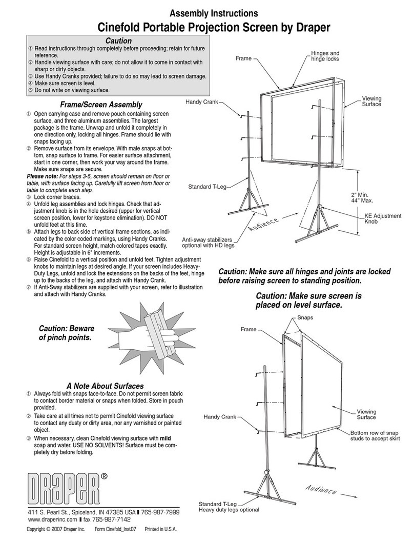
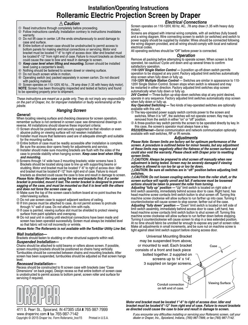
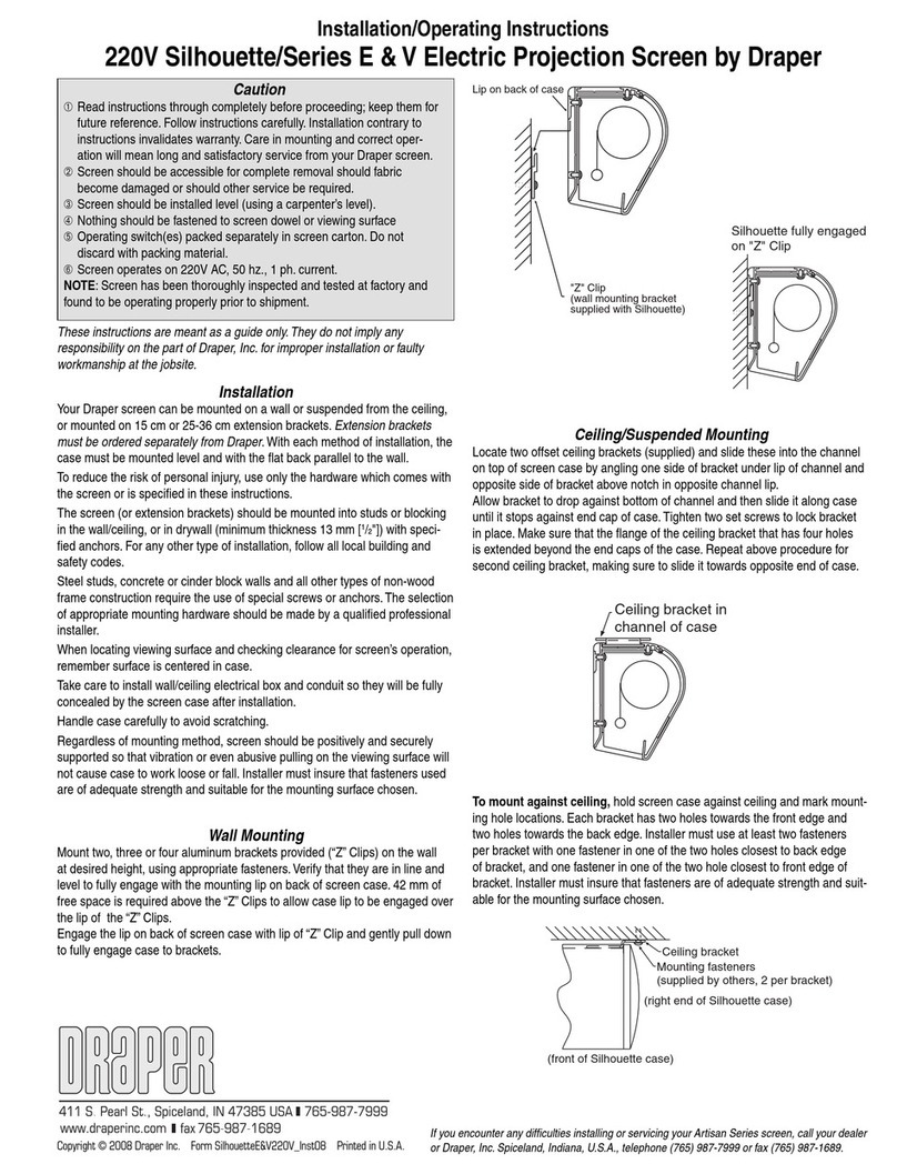
  9. Draper Premier 220V Installation instructions

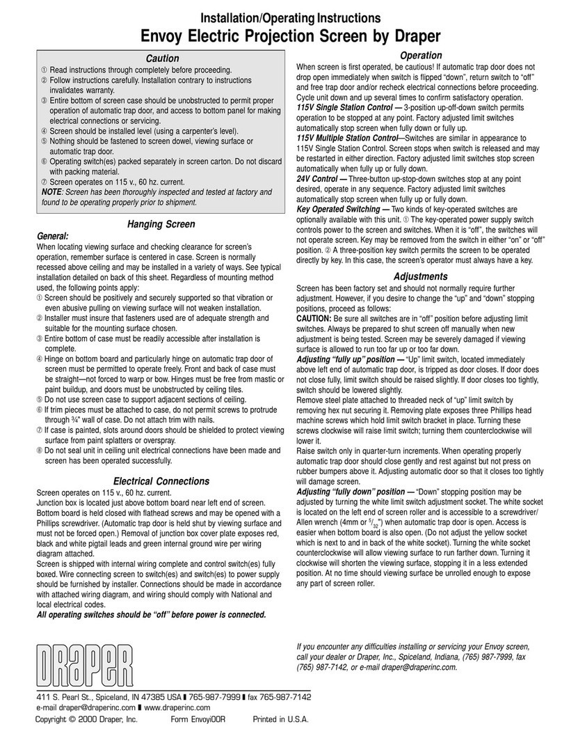
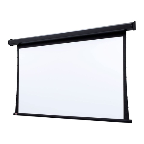
Draper Premier 220V Installation instructions

Recommended Installation Hardware and Tools
(not included)
Empfohlende Bau - und Montageteile und Werkzeuge
(nicht enthalten)
Matériel et outils d'installation recommandés
(non inclus)
CAUTION: Caution: The installation must be wired and connected
by a certified electrician.
ACHTUNG: Der Einbau und die Verdrahtung müssen
von einem zertifizierten Elektriker vorgenommen werden.
ATTENTION: Le câblage et les branchements de l'installation
doivent être effectués par un électricien certifié.
Please Note: Installer is responsible for selection of appropriate installation hardware and tools.
Bitte beachten: Die Auswahl der richtigen Einbau- und Montageteile und der Werkzeuge liegt in der Verantwortung des Installateurs.
Remarque: Le choix du matériel et des outils d'installation appropriés relève de la responsabilité de l'installateur.
•
Operating switch
(es)
packed separately in screen carton.
Do not discard with packing material.
•
Bitte beachten: Betriebsschalter sind separat im
Projektionsflächenkarton verpackt.
Bitte nicht mit dem Verpackungsmaterial entsorgen.
•
Le ou les commutateurs sont emballés séparément dans le carton
d'emballage de l'écran.
NOT INCLUDEDNOT INCLUDED
Draper, Inc. | 411 S. Pearl St. Spiceland, IN 47385
draperinc.com | +1-765-987-7999 | +1-800-238-7999
© 2020 All Rights Reserved | FORM: Premier_220V_Inst20
220V Premier
Electric Projection Screen
Elektrische Projektionsfläche
Écran de projection électrique
INSTALL ATION & OPER ATION
INSTRUCTIONS
INSTALLATIONS - BETRIEBSANLEITUNG
INSTRUCTIONS D'INSTALLATION
ET FONCTIONNEMENT
If you encounter any difficulties installing or servicing your Premier screen,
call your dealer or Draper, Inc., in Spiceland, Indiana, +1-765-987-7999 or fax +1-765-987-1689.
Falls Sie Schwierigkeiten beim Einbau oder bei der Wartung Ihrer Premier Projektionsfläche haben,
rufen Sie bei Ihrem Händler oder bei Draper, Inc., in Spiceland, Indiana unter +1-765-987-7999 an,
oder schicken Sie uns ein Fax unter +1-765-987-1689.
En cas de difficultés pour installer ou réparer l’écran Premier, contacter le distributeur
ou Draper, Inc., Spiceland, Indiana, par téléphone au +1-765-987-7999 ou par télécopieur au +1-765-987-1689.
1.
Mark and drill starter holes in mounting locations.
Markieren und bohren Sie Löcher in den Montagebereichen.
Marquer et percer des trous de pointage au niveau des
emplacements de montage.
2.
Install mounting hardware for ceiling suspension. Eyebolt shown
is not included.
Installieren Sie Bau- und Montageteile für die
Deckenaufhängung. Gezeigter Augenbolzen nicht enthalten.
Installer le matériel de fixation pour la suspension au plafond. Le
boulon à oeil sur l'illustration n'est pas inclus.
Ceiling Suspended Installation
(hardware not included)
Deckeninstallation
(Bau -und Montageteile nicht enthalten)
Suspension au plafond
(matériel non inclus)
•
S-Hook goes in back
hole
•
S-Haken wird in hintere
Bohrung eingeführt
•
Placer le crochet en S
dans le trou arrière
3.
Suspend screens from holes in endcaps. S-hooks, chains
(or cable)
,
and turnbuckles should be provided by installer. “S” hooks should
go through side mounting holes nearest front of endcaps.
Hängen Sie Projektionsflächen an Bohrlöchern in Stirnkappen auf.
S-Haken, Kette
(oder Drahtseil)
und Spannschrauben sollten vom
Installateur bereitgestellt werden. "S"-Haken sollten durch die
seitlichen Montagebohrungen in der Nähe der Stirnkappen passen.
Suspendre l'écran à partir des trous situés dans les embouts. Les
crochets en S, chaînes
(ou câbles)
et tendeurs doivent être fournis
par l'installateur. Les crochets en S doivent être installés dans les
trous de fixation les plus proches des embouts avant.
4.
For added safety, be sure to crimp both ends of the “S” hooks so the
screen cannot come off.
Für zusätzliche Sicherheit vergewissern Sie sich, dass beide Enden des
S-Hakens gequetscht wurden und sich nicht lösen können.
Pour plus de sécurité, pincer les deux extrémités des crochets en S de
façon à ce que l'écran ne puisse pas se détacher.
5.
Screen should be installed level
(using a carpenter’s level)
.
Die Projektionsfläche sollte waagrecht installiert werden
(eine
Wasserwaage benutzen)
.
L'écran doit être installé de niveau
(à l'aide d'un niveau à bulle)
.
page 2 of 8
220V Premier
Electric Projection Screen
Elektrische Projektionsfläche
Écran de projection électrique
Wall Mounted Installation
(Hardware not Included)
Wandmontage
(Bau -und Montageteile nicht enthalten)
Suspension murale
(matériel non inclus)
1.
Mark and drill starter holes in mounting locations.
Markieren und bohren Sie Löcher in den Montagebereichen.
Marquer et percer des trous de pointage au niveau des
emplacements de montage.
2.
Mount screen by installing appropriate mounting hardware through
holes in universal brackets and into wall.
Montieren Sie die Projektionsfläche, indem Sie die passenden
Bau- und Montageteile an den Universalhalterungen und der Wand
installieren.
Monter l'écran en installant le matériel de fixation approprié dans
les trous des supports universels et dans le mur.
3.
Screen should be installed level
(using a carpenter’s level)
.
Die Projektionsfläche sollte waagrecht installiert werden
(eine
Wasserwaage benutzen)
.
L'écran doit être installé de niveau
(à l'aide d'un niveau à bulle)
.
page 3 of 8
220V Premier
Electric Projection Screen
Elektrische Projektionsfläche
Écran de projection électrique
Operation/Electrical Connections
Betrieb/Elektrische Anschlüsse
Fonctionnement et connexions électriques
Screen operates on 220V AC, 50 Hz. or 60
Hz., 1 ph. current. Screen is shipped with
internal wiring complete and control switch
(es)
fully boxed. Wire connecting screen to
switch
(es)
and switch
(es)
to power supply
should be furnished by installer. Connections
should be made in accordance with wiring
diagram supplied, and wiring should comply
with national and local electrical codes. All
operating switches should be “Off” before
power is connected.
Die Projektionsfläche wird mit 1-Phasen-220
V-Wechselstrom, 50 Hz. oder 60 Hz., betrieben. Die
Projektionsfläche wird vollständig verdrahtet und
mit Kontrollschalter komplett verpackt verschickt.
Verbindungskabel zu dem/den Projektionsflächen-Schalter
(n)
sowie die Schalter für die Stromversorgung werden vom
Installateur bereitgestellt. Elektrische Verbindungen werden
in Übereinstimmung mit dem gelieferten Schaltplan erstellt.
Die Verkabelung muss den nationalen und örtlichen Auflagen
für Elektroinstallationen entsprechen. Bevor das Gerät
and das Stromnetz angeschlossen werden, müssen alle
Betriebsschalter auf „Aus“ stehen
L'écran fonctionne sous une alimentation
monophasée de 220 V CA, 50 Hertz ou 60 Hertz.
L'écran est livré avec un câblage interne complet
et un ou plusieurs commutateurs de commande
entièrement coffrés. Les câbles reliant l'écran au
(x)
commutateur
(s)
et le
(s)
commutateur
(s)
à l'alimentation
doivent être fournis par l'installateur. Les connexions
doivent être effectuées conformément au schéma
de câblage fourni et aux normes électriques locales
et nationales en vigueur. Tous les commutateurs de
commande doivent être réglés sur Arrêt avant de
brancher l'alimentation.
1.
Using a star key screwdriver, remove the endcap cover on the motor end of the
screen. This will expose the screen wiring.
Ein Stern Schlüssel Schraubendreher wird benutzt, um die Stirnkappen
am Motorende der Projektionsfläche zu entfernen. Dadurch wird die
Projektionsflächen-Verkabelung sichtbar.
À l'aide d'une clé tournevis de clé d’étoile, enlever le capuchon de l'embout
sur l'extrémité de l'écran où se trouve le moteur. Ceci permet de découvrir le
câblage de l'écran.
2.
Carefully pull the brown, blue, and white wires out through the cable exit
hole. Replace the endcap cover.
Ziehen Sie die braun, blauen und weißen Kabel vorsichtig durch die
Kabeldurchführung. Setzen Sie die Stirnkappen wieder ein.
Avec précaution, tirer les fils marron, bleu et blanc à travers le trou de sortie
de câble. Remettre le capuchon de l'embout en place.
3.
Wire to switch
(es)
and to power. Operating switch
(es)
packed separately
in screen carton. Do not discard with packing material. Before operating,
remove tape holding viewing screen in place.
Kabel zu Schalter
(n)
und Strom. Betriebsschalter sind separat im
Projektionsflächenkarton verpackt. Bitte nicht mit dem Verpackungsmaterial
entsorgen. Vor der Inbetriebnahme entfernen Sie bitte das Klebeband, durch
welches die Projektionsfläche in Position gehalten wird.
Connecter les fils au
(x)
commutateur
(s)
et au secteur. Le ou les
commutateurs sont emballés séparément dans le carton d'emballage de
l'écran. Ne pas les jeter avec le matériel d'emballage. Avant l'utilisation,
retirer le ruban en portent l'écran de visualisation en place.
Tab-Tension Adjustment Procedure for Premier
Vorgehensweise zur Einstellung der Laschenspannung der Premier
Procédure d’ajustement des languettes-tension pour l'écran Premier
Depress spring-loaded adjustment screw. Slowly turn clockwise to tighten or counterclockwise to
loosen. The screw adjusts in ¼ turn increments. Adjust only one increment
(¼ turn)
at a time. Leave
screen in position for 24 hours to allow surface material to stretch into position.
Entspannen Sie die gefederten Einstellungsschrauben. Zum Feststellen langsam im Uhrzeigersinn, zum
Lösen gegen den Uhrzeigersinn drehen. Die Einstellung der Schraube erfolgt in
¼
- Drehungsschritten.
Einstellung bitte nur in jeweils einem Schritt
(jeweils
¼
Drehung)
. Lassen Sie die Projektionsfläche 24
Stunden lang in Position hängen, damit sich das Oberflächenmaterial in Position streckt.
Appuyer sur la vis de réglage à ressort. Tourner lentement vers la droite pour augmenter la tension, ou
vers la gauche pour la réduire. La vis se règle par quarts de tour. Lors du réglage, ne tourner la vis que
d'un cran
(1⁄4 de tour)
à chaque fois. Laisser l'écran en position pendant 24 heures pour permettre au
revêtement de surface de s'étirer à la bonne position.
PUSH & TURN
CLOCKWISE
to INCREASE TENSION
PUSH & TURN
COUNTER-CLOCKWISE
to RELEASE TENSION
END OF
DOWEL
END OF
DOWEL
page 4 of 8
220V Premier
Electric Projection Screen
Elektrische Projektionsfläche
Écran de projection électrique
Limit Adjustments—Standard Motor
Grenzanpassungen—Standardmotor
Réglage des limites : moteur standard
"Down" Limit Adjustment
1.
Operate screen surface about 30 cm above desired setting and turn off.
2.
Turn the DOWN limit screw clockwise to decrease screen drop, and counterclockwise to increase screen
drop
(three screw turns = ½ roller revolution)
.
"Up" Limit Adjustment
1.
Lower screen surface about 30 cm below desired setting and turn off.
2.
Turn the UP limit screw clockwise to set "up" at a lower position, and counterclockwise to raise the "up"
position
(three screw turns = ½ roller revolution)
.
"AB" GRENZANPASSUNG
1.
Bewegen Sie die Projektionsfläche ca. 30 cm über die gewünschte Position und schalten Sie sie aus.
2.
Drehen Sie die Begrenzungsschraube für AB im Uhrzeigersinn, um das Ausfahren der Projektionsfläche zu
verringern, und gegen den Uhrzeigersinn, um es zu erhöhen
(drei Schraubendrehungen =
½
Rollendrehung)
.
"AUF" GRENZANPASSUNG
1.
Senken Sie die Projektionsfläche ca. 30 cm unter die gewünschte Position und schalten Sie sie aus.
2.
Drehen Sie die Begrenzungsschraube für AUF im Uhrzeigersinn, um die "Auf" – Fixierung auf eine iefere
position zu bringen, und gegen den Uhrzeigersinn, um die "Auf" – Fixierung auf eine höhere position zu
bringen
(drei Schraubendrehungen =
½
Rollendrehung)
.
RÉGLAGE DE LA LIMITE INFÉRIEURE
(« DOWN »)
1.
Monter l'écran à environ 30 cm au-dessus du réglage souhaité et l'éteindre.
2.
Tourner la vis de limite inférieure vers la droite pour abaisser l'image, ou vers la gauche pour élever l'image
jusqu'à l'hauteur désirée
(trois tours de vis =
½
tour de rouleau)
.
RÉGLAGE DE LA LIMITE SUPÉRIEURE
(« UP »)
1.
Abaisser l'écran à environ 30 cm en dessous du réglage souhaité et l'éteindre.
2.
Tourner la vis de limite supérieure vers la droite pour régler la limite supérieure à une position plus basse,
ou vers la gauche pour la régler à une position plus élevée
(trois tours de vis =
½
tour de rouleau)
.
Benötigte Werkzeuge: Taschenlampe, kleiner Flachschraubendreher/Hex-Schlüssel
(4 mm oder
5/32
Zoll)
.
Hinweis: Die Leinwandbegrenzungen wurden werkseitig eingestellt, um optimale Eigenschaften der Leinwand zu gewährleisten. Unten wird eine Prozedur für kleinere
Feineinstellungen beschrieben, eine Einstellung dieser Begrenzungen kann sich jedoch negativ auf die Ebenheit der Leinwandoberfläche auswirken und kann auch
zum Verlust der Gewährleistung führen. Bitte wenden Sie sich an Draper, bevor Sie Leinwandbegrenzungen einstellen.
ACHTUNG: Seien Sie immer darauf vorbereitet, beim Überprüfen von neuen Einstellungen die Projektionsfläche manuell auszuschalten. Die Projektionsfläche
kann schwer beschädigt werden, wenn sie zu hoch oder zu tief gefahren wird.
Die Motorbegrenzungsschrauben befinden sich normalerweise an der linken Ansichtsseite der Projektionsflächenrolle, und die Projektionsfläche wird über die
hintere Seite der Rolle aufgerollt
Outils nécessaires: Lampe torche, petit tournevis plat ou clé hexagonale
(4 mm ou
5/32
po)
.
Veuillez noter: Les limites des écrans dont définies en usine pour une performance optimale. Vous trouverez ci-dessous comment effectuer des changements
mineurs, mais tout ajustement de ces limites peut avoir un effet négatif sur la planéité de la surface de l'écran et pourrait aussi annuler la garantie. Veuillez contacter
Draper avant de redéfinir les limites de l'écran.
ATTENTION: Toujours être prêt à désactiver manuellement l’écran lorsque les nouveaux réglages sont testés. En effet, il risque d'être gravement endommagé si la
surface de visualisation remonte ou descend trop loin.
Les vis de limite du moteur sont normalement situées à gauche du rouleau lorsque l'on est face à l'écran, et la surface de projection se déroule par l'arrière du
rouleau.
Tools needed: Flashlight, small flathead screwdriver/hex key
(4mm or
5/32
")
.
Please Note: Screen limits are factory set for optimum performance of the screen. A procedure is outlined below for minor tweaks, but any adjustment
of these limits may negatively affect the flatness of the screen surface and could also void the warranty. Please check with Draper prior to resetting
screen limits.
CAUTION: Always be prepared to shut screen off manually when new adjustment is being tested. Screen may be severely damaged if viewing
surface is allowed to run too far up or too far down.
The motor limit screws are normally located on the audience left of screen roller, and the viewing surface rolls off the back of the roller.
page 5 of 8
220V Premier
Electric Projection Screen
Elektrische Projektionsfläche
Écran de projection électrique
Limit Adjustments—Quiet Motor
Grenzanpassungen—Leise Motor
Réglage des limites—moteur silencieux
"Down" Limit Adjustment
1.
Operate screen surface about 30 cm above desired setting and turn off.
2.
Turn the DOWN limit screw
(I)
clockwise to decrease screen drop, and counterclockwise to increase
screen drop
(three screw turns = ½ roller revolution)
.
"Up" Limit Adjustment
1.
Lower screen surface about 30 cm below desired setting and turn off.
2.
Turn the UP limit screw
(II)
clockwise to set "up" at a lower position, and counterclockwise to raise the "up"
position
(three screw turns = ½ roller revolution)
.
"Ab" Grenzanpassung
1.
Bewegen Sie die Projektionsfläche ca. 30 cm über die gewünschte Position und schalten Sie sie aus.
2.
Drehen Sie die Begrenzungsschraube
(I)
für AB im Uhrzeigersinn, um das Ausfahren der Projektionsfläche
zu verringern, und gegen den Uhrzeigersinn, um es zu erhöhen
(drei Schraubendrehungen =
½
Rollendrehung)
.
"Auf" Grenzanpassung
1.
Senken Sie die Projektionsfläche ca. 30 cm unter die gewünschte Position und schalten Sie sie aus.
2.
Drehen Sie die Begrenzungsschraube
(II)
für AUF im Uhrzeigersinn, um die "Auf" – Fixierung auf eine tiefere
position zu bringen, und gegen den Uhrzeigersinn, um die "Auf" – Fixierung auf eine höhere position zu
bringen
(drei Schraubendrehungen =
½
Rollendrehung)
.
Réglage De La Limite Inférieure
(« Down »)
1.
Monter l'écran à environ 30 cm au-dessus du réglage souhaité et l'éteindre.
2.
Tourner la vis de limite inférieure
(I)
vers la droite pour abaisser l'image, ou vers la gauche pour élever
l'image jusqu'à l'hauteur désirée
(trois tours de vis =
½
tour de rouleau)
.
Réglage De La Limite Supérieure
(« Up »)
1.
Abaisser l'écran à environ 30 cm en dessous du réglage souhaité et l'éteindre.
2.
Tourner la vis de limite supérieure
(II)
vers la droite pour régler la limite supérieure à une position plus
basse, ou vers la gauche pour la régler à une position plus élevée
(trois tours de vis =
½
tour de rouleau)
.
Tools needed: Flashlight, small flathead screwdriver/hex key
(4mm or
5/32
")
.
Please Note: Screen limits are factory set for optimum performance of the screen. A procedure is outlined below for minor tweaks, but
any adjustment of these limits may negatively affect the flatness of the screen surface and could also void the warranty. Please check
with Draper prior to resetting screen limits.
CAUTION: Always be prepared to shut screen off manually when new adjustment is being tested. Screen may be severely damaged
if viewing surface is allowed to run too far up or too far down.
The motor limit screws are normally located on the audience left of screen roller, and the viewing surface rolls off the back of the
roller.
Benötigte Werkzeuge: Taschenlampe, kleiner Flachschraubendreher/Hex-Schlüssel
(4 mm oder
5/32
Zoll)
.
Hinweis: Die Leinwandbegrenzungen wurden werkseitig eingestellt, um optimale Eigenschaften der Leinwand zu gewährleisten. Unten wird eine Prozedur für kleinere
Feineinstellungen beschrieben, eine Einstellung dieser Begrenzungen kann sich jedoch negativ auf die Ebenheit der Leinwandoberfläche auswirken und kann auch
zum Verlust der Gewährleistung führen. Bitte wenden Sie sich an Draper, bevor Sie Leinwandbegrenzungen einstellen.
ACHTUNG: Seien Sie immer darauf vorbereitet, beim Überprüfen von neuen Einstellungen die Projektionsfläche manuell auszuschalten. Die Projektionsfläche
kann schwer beschädigt werden, wenn sie zu hoch oder zu tief gefahren wird.
Outils nécessaires: Lampe torche, petit tournevis plat ou clé hexagonale
(4 mm ou
5/32
po)
.
Veuillez noter: Les limites des écrans dont définies en usine pour une performance optimale. Vous trouverez ci-dessous comment effectuer des changements
mineurs, mais tout ajustement de ces limites peut avoir un effet négatif sur la planéité de la surface de l'écran et pourrait aussi annuler la garantie. Veuillez contacter
Draper avant de redéfinir les limites de l'écran.
ATTENTION: Toujours être prêt à désactiver manuellement l’écran lorsque les nouveaux réglages sont testés. En effet, il risque d'être gravement endommagé si la
surface de visualisation remonte ou descend trop loin.
Les vis de limite du moteur sont normalement situées à gauche du rouleau lorsque l'on est face à l'écran, et la surface de projection se déroule par l'arrière du
rouleau.
page 6 of 8
220V Premier
Electric Projection Screen
Elektrische Projektionsfläche
Écran de projection électrique
Wiring Diagrams—220V Standard Motor
Schaltpläne—220 V Standardmotor
Schémas de câblage : moteur standard 220 V
External Low Voltage and Wireless
Externe Niederspannung und kabellos
Basse tension externe et sans fil
Please Note: Do not wire motors in parallel Bitte beachten: Motoren nicht parallel schalten Remarque: Ne pas connecter les moteurs en parallèle.
GND
L1
N
White - Common to screen & 230V AC Neutral
Red - to screen
(directional)
Brown - to 230V AC-Hot
Yellow - to 230V AC-Hot
Black - to 230V AC-Hot
Green/Yellow
(Ground)
Dashed wiring by electrician
Factory wiring
Low-voltage wiring by others
IR Eye Input
LVC-IV motor lead bundle
LVC-IV AC power input bundle
Low-Voltage
Trigger
4-28 VDC
RS232/485
Inputs/Outputs
3 Button Wall Switch
DOWN - Black
COM - White
UP - Red
Wall Switch
Electrically Straight
Data Cable to more
LVC-IV modules.*
Location of key
operated on-off
switch if furnished.
To
230 VAC
Line
*A maximum of six (6)
LVC-IV modules can
be linked together.
Receiver
Button
FUSE - 3.15 AMP
250 VAC 5x 20mm
External LVC-IV - Single or Multiple Projection Screen Wiring Diagram - 220V
Blue
(Common)
Black
(Up)
Brown
(Down)
INTERNAL SCREEN WIRING
Green/Yellow
(Motor Ground)
TO: MOTOR LEADS
Neutral
L1
220v,
50 Hz. or/oder/ou 60 Hz.
Dashed wiring
by installer/
Gestrichelte Verkabelung
durch Installateur/
Câblage en pointillés
par l'installateur
Control
switch/
Kontrollschalter/
Commutateur de commande
Single Station Control/Einstationsbedienung/
Commande monoposte
CE Approved/CE-zugelassen/Homologuée CE
Internal Screen Wiring/Interne
Projektionsflächenverkablung/Câblage interne de l'écran
Blue/Blau/Bleu-220v (Common/Gemeinsam/Commun)
Brown/Braun/Marron-220v (Down/Ab/Bas)
Black/Schwarz/Noir-220v (Up/Auf/Haut)
Neutral
Hot/
Stromführend/
Chaud
Multiple Station Control/Mehrstationsbedienung/
Commande multiposte
Not CE Approved/Nicht CE-zugelassen/Non homologuée CE
Red/Rot/Rouge
Red/Rot/Rouge
Red/Rot/Rouge
Blue/
Blau/
Bleu
Blue/
Blau/
Bleu
Blue/
Blau/
Bleu
Black/Schwarz/Noir
Black/Schwarz/Noir
220v, 50 Hz. or/oder/ou 60 Hz.
Black/Schwarz/Noir
Green-Yellow/Grün-Gelb/Vert-jaune
(Motor Ground/Motorerdung/
mise à la terre du moteur)
Control
switches/
Kontrollschalter/
Commutateurs
de commande
Internal Screen Wiring/Interne
Blue/Blau/Bleu-220v (Common/Gemeinsam/Commun)
Brown/Braun/Marron-220v (Down/Ab/Bas)
Black/Schwarz/Noir-220v (Up/Auf/Haut)
Green-Yellow/Grün-Gelb/Vert-jaune
(Motor Ground/Motorerdung/
mise à la terre du moteur)
Dashed wiring
by installer/
Gestrichelte Verkabelung
durch Installateur/
Câblage en pointillés
par l'installateur
Neutral
L1
220v,
50 Hz. or/oder/ou 60 Hz.
Dashed wiring
by installer/
Gestrichelte Verkabelung
durch Installateur/
Câblage en pointillés
par l'installateur
Control
switch/
Kontrollschalter/
Commutateur de commande
Single Station Control/Einstationsbedienung/
Commande monoposte
CE Approved/CE-zugelassen/Homologuée CE
Internal Screen Wiring/Interne
Projektionsflächenverkablung/Câblage interne de l'écran
Blue/Blau/Bleu-220v (Common/Gemeinsam/Commun)
Brown/Braun/Marron-220v (Down/Ab/Bas)
Black/Schwarz/Noir-220v (Up/Auf/Haut)
Neutral
Hot/
Stromführend/
Chaud
Multiple Station Control/Mehrstationsbedienung/
Commande multiposte
Not CE Approved/Nicht CE-zugelassen/Non homologuée CE
Red/Rot/Rouge
Red/Rot/Rouge
Red/Rot/Rouge
Blue/
Blau/
Bleu
Blue/
Blau/
Bleu
Blue/
Blau/
Bleu
Black/Schwarz/Noir
Black/Schwarz/Noir
220v, 50 Hz. or/oder/ou 60 Hz.
Black/Schwarz/Noir
Green-Yellow/Grün-Gelb/Vert-jaune
(Motor Ground/Motorerdung/
mise à la terre du moteur)
Control
switches/
Kontrollschalter/
Commutateurs
de commande
Internal Screen Wiring/Interne
Blue/Blau/Bleu-220v (Common/Gemeinsam/Commun)
Brown/Braun/Marron-220v (Down/Ab/Bas)
Black/Schwarz/Noir-220v (Up/Auf/Haut)
Green-Yellow/Grün-Gelb/Vert-jaune
(Motor Ground/Motorerdung/
mise à la terre du moteur)
Dashed wiring
by installer/
Gestrichelte Verkabelung
durch Installateur/
Câblage en pointillés
par l'installateur
External LVC-IV Junction Box
2.214"
(56mm)
4.5"
(114mm)
10.39"
(264mm)
MOTOR LEADS
WALL SWITCH
AC POWER INPUT
WARNING
DRY CONTACT
CLOSURE ONLY.
APPLYING VOLTAGE
HERE WILL DAMAGE
CONTROLLER.
RF Antenna
Wire
page 7 of 8
220V Premier
Electric Projection Screen
Elektrische Projektionsfläche
Écran de projection électrique
Case Dimensions
Gehäuseabmessungen
Dimensions du boîtier
PLEASE NOTE: Built-In LVC-IV will increase overall case length by 1
⁄
"
(46mm)
.
BITTE BEACHTEN SIE: Intern LVC-IV wird die Gesamtlänge um 1
⁄
"
(46mm)
erhöhen.
S'IL VOUS PLAÎT NOTE: Construit dans la LVC- IV va augmenter la longueur totale de cas de 1
⁄
"
(46mm)
.
2⁄"
(59mm)
5⁄"
(149mm)
5¼"
(133mm)
⁄"
(22mm)
dia.
electrical connection
hole
2⁄"
(54mm)
Viewing Surface
Fabric width + 7"
(178mm)
Accessing Built-In Low-Voltage Control Unit
(LVC-IV)
Zugreifen in Niederspannungsregler gebaut
(LVC-IV)
Un accès intégré Unité de contrôle basse tension
(LVC-IV)
1.
Remove the two
(2)
star head
screws from the motor end of
the screen housing.
2.
Remove the access panel with
the LVC-IV from the screen
housing.
PLEASE NOTE: Built-In LVC-
IV will increase overall case
length by 38mm.
1.
Entfernen Sie die zwei
(2)
Stern Schlüsselschrauben
aus dem Motor Ende des
Siebgehäuses.
2.
Entfernen Sie die Abdeckung
mit der LVC-IV aus der
Schirmgehäuse.
BITTE BEACHTEN SIE:
Intern LVC-IV wird die
Gesamtlänge um 38mm
erhöhen.
1.
Retirez les deux
(2)
vis de tête
d’étoiledu moteur extrémité de
l'écran de projection.
2.
Retirez le panneau d'accès avec
la LVC-IV de la cas de l'écran.
S'IL VOUS PLAÎT NOTEZ:
Construit dans la LVC-IV va
augmenter la longueur totale de
cas de 38mm.
Remove two (2)
screws from
endcap.
Remove
access panel
with LVC-IV.
*A second electrical connection hole
is included in the screen housing
in order to separate Low-Voltage
and High-Voltage Wiring.
Electrical
Connection
Hole*
page 8 of 8
220V Premier
Electric Projection Screen
Elektrische Projektionsfläche
Écran de projection électrique

Other Draper Projection Screen manuals

Draper Loke User manual

Draper

Draper Loke User manual

Draper Rolleramic Electric Projection Screen Manual

Draper

Draper Rolleramic Electric Projection Screen Manual

Draper Traveller User manual

Draper

Draper Traveller User manual

Draper Cinefold User manual

Draper

Draper Cinefold User manual

Draper Silhouette C Series Manual

Draper

Draper Silhouette C Series Manual

Draper Nocturne+E Programming manual

Draper

Draper Nocturne+E Programming manual

Draper Premier XL Programming manual

Draper

Draper Premier XL Programming manual

Draper nocturne+ c Programming manual

Draper

Draper nocturne+ c Programming manual

Draper Clarion User manual

Draper

Draper Clarion User manual

Draper Access Fit Series User manual

Draper

Draper Access Fit Series User manual

Draper Paragon Series Manual

Draper

Draper Paragon Series Manual

Draper 220V Access Electric Projection Screen User manual

Draper

Draper 220V Access Electric Projection Screen User manual

Draper Targa Manual

Draper

Draper Targa Manual

Draper Access MultiView Series Manual

Draper

Draper Access MultiView Series Manual

Draper VCB Silhouette E series User manual

Draper

Draper VCB Silhouette E series User manual

Draper Targa 220V Manual

Draper

Draper Targa 220V Manual

Draper Signature/Series V Manual

Draper

Draper Signature/Series V Manual

Draper Envoy Manual

Draper

Draper Envoy Manual

Draper 218031 User manual

Draper

Draper 218031 User manual

Draper 220V Signature/Series E Manual

Draper

Draper 220V Signature/Series E Manual

Draper Premier User manual

Draper

Draper Premier User manual

Draper Paragon V Series Manual

Draper

Draper Paragon V Series Manual

Draper Premier Manual

Draper

Draper Premier Manual

Draper Artisan Series Manual

Draper

Draper Artisan Series Manual

Popular Projection Screen manuals by other brands

Stewart Audio AB Electriscreen owner's manual

Stewart Audio

Stewart Audio AB Electriscreen owner's manual

Da-Lite C with CSR operating instructions

Da-Lite

Da-Lite C with CSR operating instructions

Celexon Expert operating instructions

Celexon

Celexon Expert operating instructions

LUMENE MOVIE PALACE 600C manual

LUMENE

LUMENE MOVIE PALACE 600C manual

Elite Screens Lunette Series user guide

Elite Screens

Elite Screens Lunette Series user guide

Da-Lite ASCENDER ELECTROL Instruction book

Da-Lite

Da-Lite ASCENDER ELECTROL Instruction book

Cima Above Ceiling ElectriScreen owner's manual

Cima

Cima Above Ceiling ElectriScreen owner's manual

Tate Office Containment Partitions Operation & maintenance guide

Tate

Tate Office Containment Partitions Operation & maintenance guide

Genius Sierra 800 troubleshooting guide

Genius

Genius Sierra 800 troubleshooting guide

Elite Screens TE100HC2 Specifications

Elite Screens

Elite Screens TE100HC2 Specifications

Elite Screens Vmax Series user guide

Elite Screens

Elite Screens Vmax Series user guide

SkillKorp GS10 manual

SkillKorp

SkillKorp GS10 manual

Zenith Presentation PRO900X Installation and setup guide

Zenith

Zenith Presentation PRO900X Installation and setup guide

Da-Lite Picture King Instruction book

Da-Lite

Da-Lite Picture King Instruction book

Vivid VFS390SM user manual

Vivid

Vivid VFS390SM user manual

TL Elektronic INTEGRA EMS TL-6760 Configuration manual

TL Elektronic

TL Elektronic INTEGRA EMS TL-6760 Configuration manual

Da-Lite TENSIONED DIRECTOR ELECTROL Instruction book

Da-Lite

Da-Lite TENSIONED DIRECTOR ELECTROL Instruction book

Elite Screens aeonclr series user guide

Elite Screens

Elite Screens aeonclr series user guide

manuals.online logo
manuals.online logoBrands
  • About & Mission
  • Contact us
  • Privacy Policy
  • Terms and Conditions

Copyright 2025 Manuals.Online. All Rights Reserved.