manuals.online logo
Brands
  1. Home
  2. •
  3. Brands
  4. •
  5. Draper
  6. •
  7. Projection Screen
  8. •
  9. Draper Lace & Grommet Installation instructions

Draper Lace & Grommet Installation instructions

Section 1 - Preparation
Section 1.1
-
Preparing to Unpack the Screen
The shipping container is marked to indicate the top of the screen and to give instructions as to whether the screen will unroll from stage right or left.
Large screens should be properly located before removing to avoid unnecessary handling after removal from the shipping container.
Section 1.2
-
Removing Screen from Shipping Container
The screen should not be lifted from the shipping case, but should be handled by rolling the case on its side, after carefully removing the lid and making
certain that all nails, splinters of wood, or staples that might damage the screen are removed. This eliminates the danger of a large screen sagging as it would
if lifted by its ends alone.
Section 1.3 -
Supporting Screen Unrolled Across Frame
A rolling dolly or a plate and peg to insert in the bottom of the screen tube should be prepared before raising the screen to its vertical position.
This will hold the screen at the proper height relative to the frame and relieve the strain that would otherwise fall on the stagehands working on the bottom of
the screen. A swivel eye at the top of the screen mounting tube can perform the same function.
Section 1.4
-
Frame Assembly Location
The frame can be assembled on the floor, on the wall, or as it hoisted into position. If you are planning to suspend this screen,
it is advisable to use block and fall or other hoisting equipment to assemble and raise the screen section by section.
1. Assemble the top horizontal frame member, and attach the top of the viewing surface.
2. Raise this portion of the screen until the vertical members from each side can be attached.
3. Attach vertical frame pieces and hook the viewing surface to the frame, and raise as you go.
For wall mounting, the screen can be assembled on the wall or on the floor and then raised into place.
Section 1.5
-
Final Tensioning
Starting at the proper side, carefully begin to unroll the screen. Insert a hook in the top corner grommet and also a few equally spaced along the top to hold
it in position as the screen is unrolled. Do not attempt to insert hooks in every grommet as you proceed to unroll, but rather every fourth or fifth one until the
screen is temporarily suspended. Then go around again two or more times, placing only alternating hooks.This will permit the tension to be applied evenly
around the screen and fewer subsequent adjustments will be required to obtain a perfectly flat surface.
Section 1.6
-
For screens with curved frames
Use only minimum tension sufficient to hold screen in place at the sides in order to minimize reverse curvature in the center. This can be accomplished by
inserting hooks in every second or third grommet.
CAUTION! Stagehands must support top, the sides and bottom while the screen is being assembled and raised. Handle the viewing surface gently.
DO NOT CRUSH OR PINCH. PROTECT THE VIEWING SURFACE IN EVERY WAY POSSIBLE.
Lace & Grommet
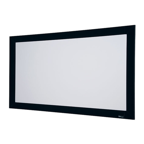
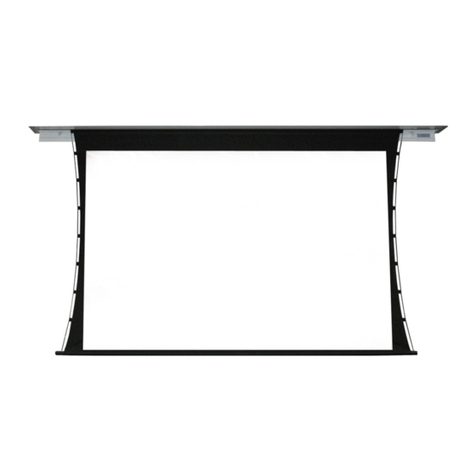
Permanently Tensioned Projection Screen
CAUTION
1. Please read all instructions before installing. Follow all instructions
carefully. Failure to install or use this product in accordance with the
enclosed instructions will void your warranty.
2. Screen is typically packed with all frame pieces packed together, but
individually wrapped and protected. Be careful when opening the
shipping container not to scratch or dent the tubing.
3. Handle the viewing surface gently. Don’t crush or pinch; protect the
front surface in every way possible.
4. Use extreme care when handling TecVision surfaces.
To prevent damaging the TecVision viewing surface, Draper strongly
reccommends using the provided white gloves.
Please Note:
Custom products/installations may not be reflected by this document.
Call Draper, Inc. if you have questions about your installation.
Draper, Inc. | 411 S. Pearl St. Spiceland, IN 47385
draperinc.com | 765.987.7999 | 800.238.7999
© 2017 All Rights Reserved
|
FORM: LaceGrommet_Inst17.indd
INSTRUCTIONS
INSTALLATION & OPERATION
TOOLS REQUIRED
PENCIL TAPE
MEASURE
POWER
DRILL
LEVEL GLOVES
(TecVision Only)
MOUNTING
HARDWARE
(by Others)
Lace & Grommet
Permanently Tensioned Projection Screen
page 2 of 4
WALL
AT LEAST
18”
CENTER
TOP OF FRAME
BOTTOM OF FRAME
VIEWING
SURFACE
BOTTOM
BRACKETS
ROTATED
180°
Fixed Wall Bracket
Attached to Wall Stud
Securing Bottom of Frame
Fixed Wall Bracket
Attached to Wall Stud
with Frame Hanging
Bungees Properly
Attached to Tube
and Viewing Surface
Figure 4
Attachment Bolt
Figure 3
Figure 2
Section 4 - Frame Assembly
Each tube will be labeled with numbers, always starting with the Upper Stage
Right Corner piece, and moving clockwise around the perimeter of the frame.
In other words Upper Stage Right Corner (top point) will have a “1” and the
next tube section moving horizontally across the top will also have an “1”.
Move clockwise joining “1” to “1”, “2” to “2”, “3” to “3”, etc (see Fig. 2).
Join tubing together by sliding inserts into open tube. Lock together hand
tightening the provided attachment bolts into the black tubing at each joint
(see Figs. 3 and 4).
Please Note:
After hand tightening attach-
ment bolts, a ½" ratchet or
wrench should
be used to tighten each bolt.
Be sure to review each tube piece to assure bungee and hooks are secured in
the tubing before attaching the surface to the hooks (see below).
Section 3 - Wall Brackets
Brackets must be secured and properly anchored into the wall with appropriate support.
Do not apply a bracket just into drywall. Support needs to secure to stud work or
through ½" thick or larger supported plywood.
Please Note: If using the Extension Bracket, mount the Wall Mounting Plate first;
set the bracket and tighten in place.
After mounting the wall bracket, you can set the Lace and Grommet frame tube into place.
CAUTION! Make sure to tighten the setscrews to hold the frame securely in place in the bracket. Failure to lock the frame into place on the bracket could result in
the frame coming out of the bracket, creating the possibility of damage to the frame and injuries to bystanders.
Hole for setting extension
from wall. Use
3
/
8
" lag bolt.
Setscrews for locking
frame into bracket
Figure 1
Lace & Grommet
Permanently Tensioned Projection Screen
page 3 of 4
Figure 5 Figure 6
Figure 7
WALL
AT LEAST
18”
CENTER
TOP OF FRAME
BOTTOM OF FRAME
VIEWING
SURFACE
BOTTOM
BRACKETS
ROTATED
180°
Fixed Wall Bracket
Attached to Wall Stud
Securing Bottom of Frame
Fixed Wall Bracket
Attached to Wall Stud
with Frame Hanging
Bungees Properly
Attached to Tube
and Viewing Surface
Section 5 - Optional Trim
If you order your Lace and Grommet screen with optional trim, the Frame Corners will come with the trim automatically attached (see Fig. 5).
To attach trim to the frame, use included self-tapping screws.
Make sure the end of each trim piece matches the frame section joints, and that they line up evenly across the screen (see Fig. 6).
If there are light gaps, use the included self-adhesive Vel-tex strips. Place the strips on the inside of the trim (see Fig. 7).
Vel-tex "dots" are also included to use to cover the heads of the self-tapping screws used to attach the trim to the frame.
Section 6 - Dimensions
3½"
(89mm)
11 GA C.R.S.
Ø.385" (10mm)
thru four places
2½"
(64 mm)
½"
(13 mm)
2½"
(64 mm)
4"
(101 mm) ¾" (19 mm)
17/8"
(49 mm)
37/8"
(98 mm)
23/8"
(60 mm)
7/8" (22 mm)
Ø.3"
(76 mm)
3½"
(89 mm)
37/8"
(100 mm)
MOUNT VIEW
Standard Fixed Brackets
MOUNT VIEW
2½"
(64 mm)
½"
(13 mm)
½"
(13 mm)
3½"
(89 mm)
1¾"
(44 mm)
2½"
(64 mm)
3½"
(89 mm)
1¾"
(44 mm)
10" (254 mm) max. (shown)
8" (203 mm)min.
NOTE: These dimensions vary
2"
(51 mm)
2
1
/
8
"
(55 mm)
1
7
/
8
"
(49 mm)
Ø3"
(77 mm)
8½" (215 mm)max.
6½" (165 mm)min.
11½" (293 mm) max.
9½" (241 mm) min.
2½"
(64 mm)
Optional Extension Brackets
Lace & Grommet
Permanently Tensioned Projection Screen
page 4 of 4

Other Draper Projection Screen manuals

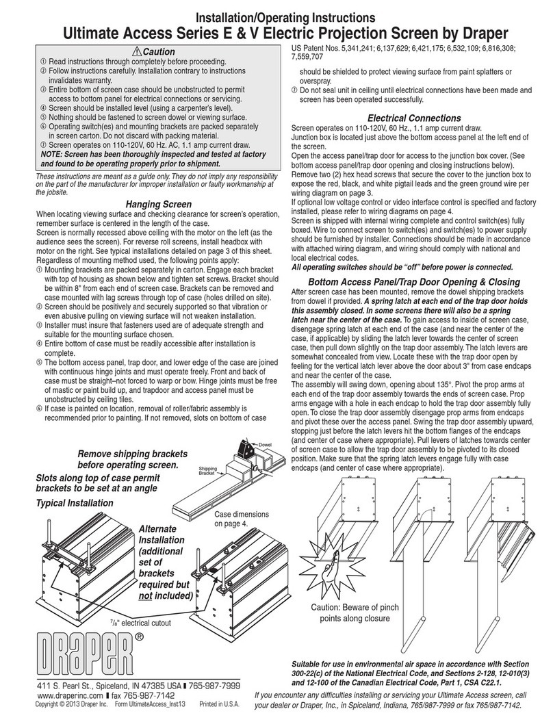
Draper Ultimate Access V Installation instructions

Draper

Draper Ultimate Access V Installation instructions

Draper 220V Signature/Series E Manual

Draper

Draper 220V Signature/Series E Manual

Draper Luma User manual

Draper

Draper Luma User manual

Draper Paragon User manual

Draper

Draper Paragon User manual

Draper Silhouette/Series V Manual

Draper

Draper Silhouette/Series V Manual

Draper Envoy Manual

Draper

Draper Envoy Manual

Draper Premier User manual

Draper

Draper Premier User manual

Draper Premier User manual

Draper

Draper Premier User manual

Draper premier User manual

Draper

Draper premier User manual

Draper Silhouette/Series E Manual

Draper

Draper Silhouette/Series E Manual

Draper Access/Series M Manual

Draper

Draper Access/Series M Manual

Draper Access M User manual

Draper

Draper Access M User manual

Draper M Series Manual

Draper

Draper M Series Manual

Draper 220V Ultimate Access User manual

Draper

Draper 220V Ultimate Access User manual

Draper Premier XL 220 User manual

Draper

Draper Premier XL 220 User manual

Draper Foundation User manual

Draper

Draper Foundation User manual

Draper Access MultiView Manual

Draper

Draper Access MultiView Manual

Draper Ultimate Access Series E Manual

Draper

Draper Ultimate Access Series E Manual

Draper Cinefold Portable Folding Projection Screen User manual

Draper

Draper Cinefold Portable Folding Projection Screen User manual

Draper Portable Projection Screen User manual

Draper

Draper Portable Projection Screen User manual

Draper Signature E Series Manual

Draper

Draper Signature E Series Manual

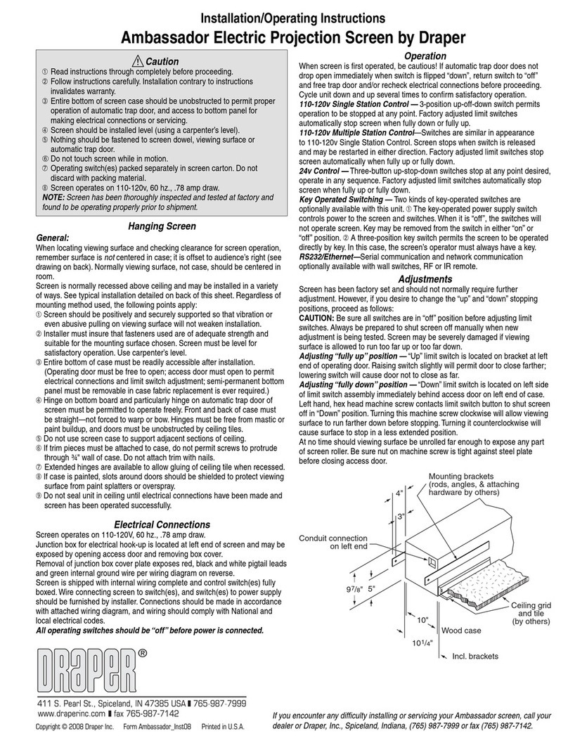
Draper Ambassador Manual

Draper

Draper Ambassador Manual

Draper Salara/Hardwire User manual

Draper

Draper Salara/Hardwire User manual

Draper 220V Access Electric Projection Screen User manual

Draper

Draper 220V Access Electric Projection Screen User manual

Popular Projection Screen manuals by other brands

THE SHOWER LAB VIEW 14.2H instructions

THE SHOWER LAB

THE SHOWER LAB VIEW 14.2H instructions

Screen Research SolidPix installation manual

Screen Research

Screen Research SolidPix installation manual

AVstumpfl FULLWHITE manual

AVstumpfl

AVstumpfl FULLWHITE manual

EliteProAV Pro Frame Acoustic Series user guide

EliteProAV

EliteProAV Pro Frame Acoustic Series user guide

EliteProAV EDGE FREE Pro Frame Thin UST Series user guide

EliteProAV

EliteProAV EDGE FREE Pro Frame Thin UST Series user guide

Stewart Filmscreen AB Electriscree owner's manual

Stewart Filmscreen

Stewart Filmscreen AB Electriscree owner's manual

EliteProAV Tab-Tension Pro Series manual

EliteProAV

EliteProAV Tab-Tension Pro Series manual

Stewart Filmscreen ABT Trapdoor Electriscreen owner's manual

Stewart Filmscreen

Stewart Filmscreen ABT Trapdoor Electriscreen owner's manual

AVstumpfl Desertscreen instructions

AVstumpfl

AVstumpfl Desertscreen instructions

Stewart Filmscreen VistaScope owner's manual

Stewart Filmscreen

Stewart Filmscreen VistaScope owner's manual

Gainsborough H433 Instructions for use

Gainsborough

Gainsborough H433 Instructions for use

Elite Screens Tab-Tension 3 Series user guide

Elite Screens

Elite Screens Tab-Tension 3 Series user guide

Elite Screens M85XWS1-SRM user guide

Elite Screens

Elite Screens M85XWS1-SRM user guide

Elite Screens OMS90H2 user guide

Elite Screens

Elite Screens OMS90H2 user guide

Elite Screens Spectrum Series user guide

Elite Screens

Elite Screens Spectrum Series user guide

LG MAGNIT All-in-One LAAA007-G2 owner's manual

LG

LG MAGNIT All-in-One LAAA007-G2 owner's manual

Naxa NTD-2460A instruction manual

Naxa

Naxa NTD-2460A instruction manual

Samsung LTN133AT08-101 Service manual

Samsung

Samsung LTN133AT08-101 Service manual

manuals.online logo
manuals.online logoBrands
  • About & Mission
  • Contact us
  • Privacy Policy
  • Terms and Conditions

Copyright 2025 Manuals.Online. All Rights Reserved.