manuals.online logo
Brands
  1. Home
  2. •
  3. Brands
  4. •
  5. Eaton
  6. •
  7. Industrial Equipment
  8. •
  9. Eaton MEMSHIELD 3 Manual

Eaton MEMSHIELD 3 Manual

Other Eaton Industrial Equipment manuals

Eaton NZM1-XBR Manual

Eaton

Eaton NZM1-XBR Manual

Eaton COOPER POWER SERIES User manual

Eaton

Eaton COOPER POWER SERIES User manual

Eaton Cutler-Hammer ATC-300 User manual

Eaton

Eaton Cutler-Hammer ATC-300 User manual

Eaton NZM4-XAS14-1600 Manual

Eaton

Eaton NZM4-XAS14-1600 Manual

Eaton XI0-EXT121-1 Manual

Eaton

Eaton XI0-EXT121-1 Manual

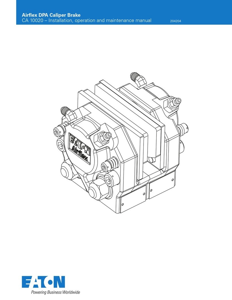
Eaton Airflex DPA User manual

Eaton

Eaton Airflex DPA User manual

Eaton Digitrip Retrofit System Manual

Eaton

Eaton Digitrip Retrofit System Manual

Eaton Airflex WCBD Series User manual

Eaton

Eaton Airflex WCBD Series User manual

Eaton Hydrowa User manual

Eaton

Eaton Hydrowa User manual

Eaton NZMB2-A Series Manual

Eaton

Eaton NZMB2-A Series Manual

Eaton XV300 Series User manual

Eaton

Eaton XV300 Series User manual

Eaton GD4-050-BD3 Manual

Eaton

Eaton GD4-050-BD3 Manual

Eaton DX-BR Series Manual

Eaton

Eaton DX-BR Series Manual

Eaton NZM1-XSV Manual

Eaton

Eaton NZM1-XSV Manual

Eaton Airflex WSB11206 User manual

Eaton

Eaton Airflex WSB11206 User manual

Eaton NZM3-XKCO Series Manual

Eaton

Eaton NZM3-XKCO Series Manual

Eaton PBHT-F Manual

Eaton

Eaton PBHT-F Manual

Eaton MMX-NET-XA Manual

Eaton

Eaton MMX-NET-XA Manual

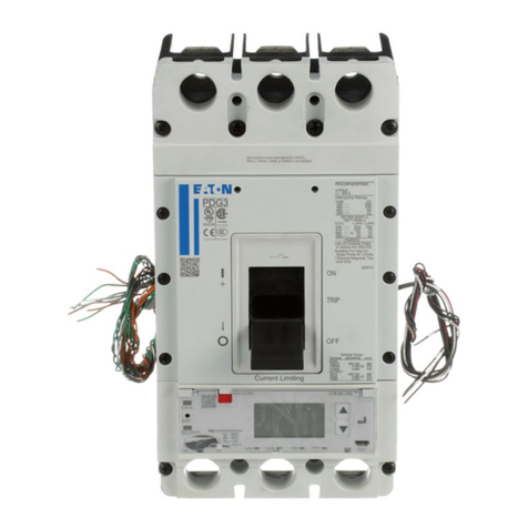
Eaton Power Defense Manual

Eaton

Eaton Power Defense Manual

Eaton CI/E-PKZ01-X Series Manual

Eaton

Eaton CI/E-PKZ01-X Series Manual

Eaton 50 VCP-WL Instruction manual

Eaton

Eaton 50 VCP-WL Instruction manual

Eaton PXR-RCAM-MRTU-I Manual

Eaton

Eaton PXR-RCAM-MRTU-I Manual

Eaton PKE12 Series Manual

Eaton

Eaton PKE12 Series Manual

Eaton MSFB Series Manual

Eaton

Eaton MSFB Series Manual

Popular Industrial Equipment manuals by other brands

ABB +Q957 user manual

ABB

ABB +Q957 user manual

G.B.C BASIC EDGE 50 instruction manual

G.B.C

G.B.C BASIC EDGE 50 instruction manual

Tronair Batpak 11-6602-1000 Operation & service manual

Tronair

Tronair Batpak 11-6602-1000 Operation & service manual

Pilz PNOZ mi2p Operation manual

Pilz

Pilz PNOZ mi2p Operation manual

Clemco Zero BNP 6012 manual

Clemco

Clemco Zero BNP 6012 manual

Erskine Attachments V-Plow Operator's manual

Erskine Attachments

Erskine Attachments V-Plow Operator's manual

ABB HT610965 Operation manual

ABB

ABB HT610965 Operation manual

Morra MH 540 user manual

Morra

Morra MH 540 user manual

GRIGGIO G 240 P4 instructions

GRIGGIO

GRIGGIO G 240 P4 instructions

Nexen AIR CHAMP HT45 user manual

Nexen

Nexen AIR CHAMP HT45 user manual

WTE V5 installation manual

WTE

WTE V5 installation manual

ABB HT845232 Operation manual

ABB

ABB HT845232 Operation manual

SMC Networks CJP Series Operation manual

SMC Networks

SMC Networks CJP Series Operation manual

JohnDow Industries JDI-AFT58 Operator's manual

JohnDow Industries

JohnDow Industries JDI-AFT58 Operator's manual

IMB MB9016A instruction manual

IMB

IMB MB9016A instruction manual

Clarke CUMB1 Assembly & operating instructions

Clarke

Clarke CUMB1 Assembly & operating instructions

amiad Arkal Spin Klin 2 user guide

amiad

amiad Arkal Spin Klin 2 user guide

Maxima GIUNTOMAX Use and maintenance manual

Maxima

Maxima GIUNTOMAX Use and maintenance manual

manuals.online logo
manuals.online logoBrands
  • About & Mission
  • Contact us
  • Privacy Policy
  • Terms and Conditions

Copyright 2025 Manuals.Online. All Rights Reserved.

ENCLOSURE MOUNTING
Toassist installation
a. Remove endplatesfor(i)drilling, (ii)forfitting
enclosure to trunking.
b. Remove Pan Assemblyby slackening NeutralBusbar
Connection ‘N1’ and the 2 panfixing screws.
c. Fix enclosure to wall
N.B. Endplate fixing screwsare of a special type provided to
ensure the endplatesare electricallybondedto the enclosure.
Do not replace with screwsof anothertype. Afterrefitting Pan
Assemblyensure Neutral linkisconnectedto ‘N1’ and all
fixing screwsare tight. RECOMMENDEDTORQUE 2.4Nm.
NOTE
Toease fitting of incomingcable theNeutralTerminal
isremovable.
1. Remove Pan assembly.
2. Remove ‘N’ assembly by slackening ‘N’ assembly
fixing screw(s) and pull in directionof arrow.
Earth Terminal
tighten to 6.8Nm
Pan Fixing
Screws
Cover
Fixing
Screws
‘N’ Assembly
‘N’ Assembly
Fixing Screws
Pan
Assembly
Incoming Device
tighten to 2.4Nm
IMPORTANT NOTES
1. This product should be installed, commissioned and maintained by or under the supervision of a competent electrician
in accordancewithcurrent electrical engineering Codes of Practice, Regulations for the Electrical equipment of
Buildings (BS7671), CDM2007 - Construction (Design and Management) Regulations 2007, HSG150 - Health and
Safety in Construction, Statutory requirements and any Specific instruction issued by the Company.
2. Aftercompleting the installation and testing of this product it is essential that this leaflet is drawnto the attention of
the person responsible for its future operation and maintenance, and is at all times available for ready reference.
3. These notes assume throughout that the product is disconnected fromthe supply.It is essential that this is done
before any workis carried out.
Earth/Neutral
terminalscrews,
tighten to 2.5Nm
MEMSHIELD 3 TYPE A SPN DISTRIBUTIONBOARD
Instruction leaflet LT1181 (01/21)
These Distribution Boards are
designed only for use with
MCB’s and RCBO’s as listed in the
current Memshield 3catalogue.
Failure to comply will result in
invalid warranty and certification.
Blanking
Module
Installation instructions as per the
standard Memshield 3 Type A Boards
whereapplicable.
Meter operating instructions can be
found on leaflet provided with digital
meter.
EAM9M/EAM9MB &
EAM12M/EAM12MB
EAMMP65
The EAMMP65 can be bolted to the left or right side of any
standard Type A Board. Connect boards together using 4 x
M6 screws and nuts provided and fit grommets in cable
holes.
Note: If the EAMMP65 board is to be bolted to the right side
of the Type A board, then the earth terminal needs remov-
ing. The earth fixing holes (2 x 7.0) need to be machined in
the mating Type A board and the earth terminal refitted
through both boards. Terminate the live connecting cable
provided, between terminal 3 of the digital meter and the
liveof the incoming device,routing it throughthegrommetted
hole, utilising the crimps on both ends of the ‘L’ connecting
cable. Likewise terminate the ‘N’ connecting cable in the
same manner between terminal N3 on the EAMMP65 ‘N’
assembly and the ‘N’ of the incoming device.
RECOMMENDED TORQUE 2.4 Nm .
Earth
Terminal
Digital
Meter
‘N’ Assembly
‘N’ Assembly
Fixing Screws
EAMSL66M/EAM66MB&
EAMSL93M/EAM93MB
Pan Assembly
Cover
Fixing
Screws
Pre-fitted
SwitchDisconnector
Incoming Device
Max rating 63A
Earth
Terminal
Digital
Meter
‘N’ Assembly
‘N’ Assembly
Fixing Screws
Pan Assembly
Pre-fitted
SwitchDisconnector
Incoming Device
Max rating 100A
IMPORTANT:
Max rating per
busbar 63A
Cover
Fixing
Screws
‘N’
Assembly
Pre-fitted
SwitchDisconnector
Incoming Device
Max rating 63A
Cover
Fixing
Screws
Terminal 3
Earth
Terminal
N3
‘N’ Assembly
Fixing Screw
Digital Meter
Earth holes
Fixing holes
Cable hole 27mm Dia.
Fixing
holes
NOTE
LOAD 1 is the bank to the left of the meter
LOAD 2 is the bank to the right of the meter
RECOMMENDEDTERMINAL SCREW
TIGHTENING TORQUE 2.4 Nm.
CAUTION:
WHEN FITTING INCOMING
DEVICES ONTO BUSBAR
ENSURE BUSBAR STAB IS
LOCATED INSIDE TERMINAL
CLAMP AND NOT UNDER-
NEATH.
Max Ratings:
SwitchDisconnector - 125A
RCCB - 90A
Direct Connection - 100A
Important
Fit rating label
supplied to cover.
FITTING BLANKING MODULEEMBP
FITTING INCOMINGDEVICE
Locate
retaining clip
Tighten
Terminal
Screws
RECOMMENDEDTERMINAL SCREW TIGHTENING TORQUE 2.4 Nm.
Locate device onto
busbar/retaining clip
FITTING CLEAN EARTHKITNEUTRALDISCONNECTION
Slacken
Terminal
Screw
ENSURE THAT NEUTRAL CONNECTOR IS CORRECTLY REFITTED AND
THAT TERMINAL SCREWS ARE RE - TIGHTENED TO TORQUE 2.4 Nm.
Slacken screw
(Terminal N1)
FITTING ANMCB/RCBO
When fitting an RCBO, trim
RCBO ‘N’ cable to length and
connect to ‘N’ busbar terminal
Locate self tapping
screws into2
holes provided
All unused ways
must be fitted with
a Blanking Module
Tighten
Terminal Screw
RECOMMENDEDTERMINAL SCREW TIGHTENING TORQUE 2.4 Nm.
Before fitting
to busbar
ensure MCB
terminalis
fullyopen
IMPORTANT:
Orientate MCB
clip nearest
to busbar
Clip this
side
Clip
fit
FITTINGEMBL2
For extrasecurity
fit padlock
List No. PD2
FITTING DOOR LOCK EMDL &EMPL
M6 KEYHOLEFIXINGS
10
130
100
OVERALLDIMENSIONS
A
37.6
161254
B
All dimensionsin
mm A B
EAM4 238 163
EAMMP65 238 163
EAM7 292 217
EAM10 346 271
EAM13 440 365
EAM9M/MB 440 365
EAM16 454 379
EAM12M/MB 454 379
EAMSL66M/MB 454 379
EAMSL93M/MB 454 379
= =
Remove
Plastic Knob
Insert Lock into hole tighten back nut
Warning-
IntellectualPropertyRights
Eaton wishestomake it clearthat it owns intellectual property rights inthe
product which it manufactures (whether or notlistedin this leaflet) and that
it will take legal action against any partyfoundtobe manufacturing, using,
or selling any article whichinfringesthe company’s intellectualproperty.All
marksinthisdocument identified with an R symbol oraTMsymbol adjacent
tothe markaretrademarks of Eaton.
C2019 EatonElectricLimited.
All rightsreserved. www.eaton.com/recycling
The use to which thisproductisputand itsplaceof installationis outsideour
control.Particularcareshouldthereforebetakentofollowtheinstructionsgiven
here and to ensure their continuedavailabilityin conjunction withtheuseof the
product.
No responsibilitycan beacceptedby usif theseinstructions are disregarded.
Further copiesof theseinstructionsand informationconcerningthe installation
and properuseof thisproductcan be obtainedby contactingthe:
Technical ServicesDepartment
Eaton Electric Limited, Middleton, Manchester, M24 1GQ. UK
Tel:+44(0)8700545333,
email: ukcommorders@eaton.com
Suitable for Indoor, Stationary applications
Mechanical Protection : IK06
IP Rating : IP3X
EMC Classification : B
Pollution Degree : 3
Construction Type : Fixed
Frequency (fn): 50Hz
MCB (2A –50A) = Rating as marked, (63A)= 55A Inc. Subject to applicable RDF - per table 101, IEC/EN61439-3
INTERFACE CHARACTERISTICS
Type A DBO to IEC/EN61439-3
Rated Voltage / Rated Operational voltage (Un / Ue) : 240V a.c.
Rated Impulse Withstand Voltage (Uimp) : 4kV
Rated Insulation Voltage (Ui) : 415V
Rated Conditional Short Circuit Current (Icc) : 15kA
Rated Current of the Assembly (InA) : See DB Rating label (65A - 125A)
Rated Diversity Factor(s) RDF : 0.7
Rated Current of each Circuit (Inc) :
RCCB (100A) = 90A Inc.
RCBO (6A-45A) = Rating as marked –subject to applicable RDF