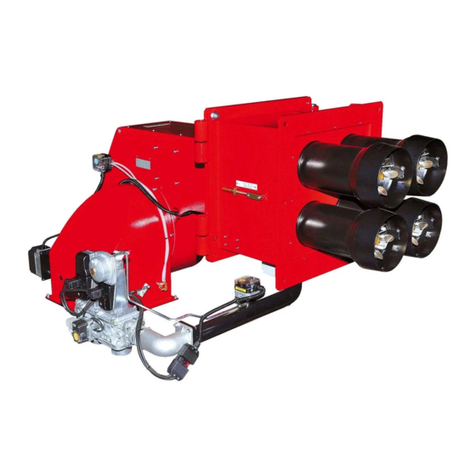
manuals.online logo
Brands
  1. Home
  2. •
  3. Brands
  4. •
  5. Ecoflam
  6. •
  7. Burner
  8. •
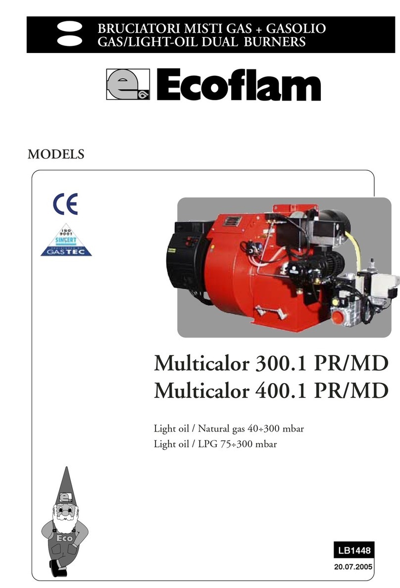
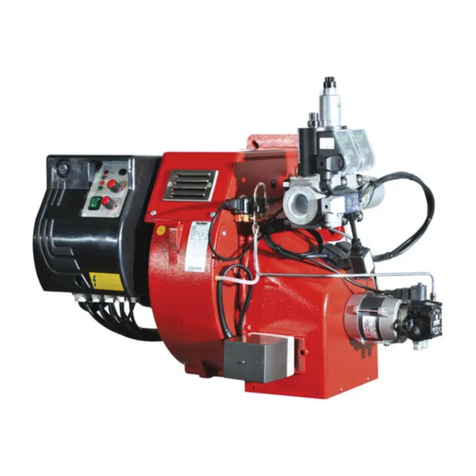
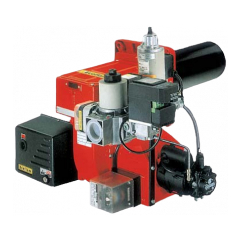
  9. Ecoflam MAIOR P 300 AB User manual

Ecoflam MAIOR P 300 AB User manual

SUNTEC
SUNTEC
SUNTEC
LB 183
18.03.99
MAIOR P 300 AB
MAIOR P 400 AB
SISTEMA IDRAULICO
HYDRAULIC SYSTEM
SYSTEME HYDRAULIQUE
SISTEMA HIDRAULICO
220/380 V 60 Hz
BRUCIATORI DI GASOLIO / OIL BURNERS
BRULEURS A MAZOUT / QUEMADOR DE GASOLEO
GASTEC
pag.2
Maior
ABCD
mbar
kcal/h
x 1000
kg/h
kW
20
3000 3400
160 180 200 220 240 260 280 300 320 340
10
12
14
16
18
3600
4000
360
1800 2400 2800 3400 38002600 3200 3600300022002000 420016001400
100 120 140
140012001000
PRESSIONE IN CAMERA DI COMBUSTIONE
PRESSURE IN THE COMBUSTION CHAMBER
PRESSION DANS LA CHAMBRE DE COMBUSTION
PRESION EN LA CAMARA DE COMBUSTION
PORTATA / BURNER OUTPUT / DEBIT / CAUDAL DEL QUEMADOR
MAIOR P 300 AB
1600 1800 2000 2200 2400 2600 2800 3200
0
2
4
6
MAIOR P 400 AB
8
CARATTERISTICHE TECNICHE / TECHNICAL DATA
CARACTERISTIQUES TECHNIQUES / CARACTERISTICAS TECNICAS
MODELLO / MODELS / MODELES / MODELOS MAIOR P 300 AB MAIOR P 400 AB
Portata termica max. / Thermal power max. kcal/h 2.550.000 3.570.000
Puissance thérmique max./ Potencia térmica máx. kW 2.965 4.151
Portata termica min. / Thermal power min. kcal/h 1.224.000 1.887.000
Puissance thérmique min / Potencia térmica mín. kW 1.423 2.194
Max. portata gasolio / Max. flow rate light oil kg/h 250 350
Débit max./ Caudal máx. de gasóleo
Min. portata gasolio / Min. flow rate light oil kg/h 120 185
Débit min./ Caudal mín. de gasóleo
Tensione aliment / Feeding power 60 Hz V 220/380 220/380
Tension d'alimentation / Aliment.eléct.
Potenza motore / Motor kW 7,5 9
Moteur / Potencia del motor
Giri -minuto / Rpm Nº 3.400 3.400
Tours par minute / Revol. por minuto
Trasf. accensione / Ignition transformer kV/mA 13/35 13/35
Transformateur / Transformador de encendido
App. controllo fiamma / Control box LANDIS LOA 44 LOA 44
Coffret de sécurité / Equipo de control de la llama
Combustibile / Fuel : gasolio / light oil kcal/kg 10.200 max. visc 1,5°E a 20°C
Combustible / Combustible : mazout / gasóleo
CURVE DI LAVORO / WORKING FIELDS / COURBE DE TRAVAIL / CURVAS DE TRABAJO
pag.3
Maior
ABCD
ED - D1
FF
G
I
L
M
C
B
A
I
O
MAIOR P 300 AB
SUNTEC
SUNTEC
SUNTEC
ED - D1
FF
G
I
L
M
C
B
A
I
O
MAIOR P 400 AB
SUNTEC
SUNTEC
SUNTEC
;;
;;;
;
;
;
;
;
;;
;
;
;
2
1345
6
7
1 - BRUCIATORE / BURNER / BRULEUR / QUEMADOR
2 - DADO / NUT / ECROU / DADO
3 - RONDELLA / WASHER / RONDELLE / ANILLO
4 - GUARNIZIONE ISOMART / GASKET / JOINT / JUNTA
5 - PRIGIONIERO / BOLT / VIS PRISONNIERS / TUERCA
6 - CALDAIA / BOILER / CHAUDIERE / CALDERA
7 - MATERIALE DI RIEMPIMENTO / GASKET
CORDON D'ETANCHEITE / CORDON AISLANTE
;;
;;
;;
;
DIMENSIONI DI INGOMBRO / OVERALL DIMENSIONS
DIMENSIONS D'ENCOMBREMENT / DIMENSIONES GLOBALES
MODELLO
MODELS ABCDD1EFGIL M
MODELES
MODELOS
P 300 AB 930 480 450 260 460 700 275 730 315 315 M14
P 400 AB 930 480 450 315 515 905 320 730 315 315 M14
D = testa corta / short head / tete courte / cabeza corta D1 = testa lunga / long head / tete longue / cabeza larga
INSTALLAZIONE DEL BRUCIATORE / BURNER INSTALLATION
MONTAGE SUR CHAUDIERE / INSTALACION DEL QUEMADOR
pag.4
Maior
ABCD
CIRCUITO IDRAULICO / HYDRAULIC CIRCUIT
CIRCUIT HYDRAULIQUE / SISTEMA HIDRÁULICO
1
1
23
1 - FLESSIBILI / HOSE / FLEXIBLES / LATIGUILLOS
2 - FILTRO / OIL FILTER / FILTRE / FILTRO
3 - RUBINETTO / OIL COCK / ROBINET D'ARRET / VÁLVULA DE CORTE
4 - ASPIRAZIONE / SUCTION / ASPIRATION / ASPIRACIÓN
5 - RITORNO / RETURN / RETOUR / RETORNO
4
5
VS
V2
V1
V3
MAIOR P 300 AB
1
1
23
MAIOR P 400 AB
H
H
H
(m)
Lunghezza tubazioni
Pipe length
Longueur tuyaux en mètres
Longitud de los tubos
ø 14 mm ø 16 mm
0
0,5
1
2
3
3,5
16
18
20
25
29
31
29
33
37
44
52
55
J 7
(m)
Bitubo dalla sommità del serbatoio
Two-pipe siphon feed system
Raccordement bitube en charge
Tubo doble de la parte superior del depósito
Bitubo in aspirazione
Two-pipe lift system
Raccordement bitube en aspiration
Tubo doble de aspiración
H
(m)
Lunghezza tubazioni
Pipe length
Longueur tuyaux en mètres
Longitud de los tubos
ø 14 mm ø 16 mm
0
0,5
1
2
3
3,5
16
14
12
7
3
1
29
26
22
14
7
4
J 7
(m)
TA2C
(m)
TA2C
(m)
ALIMENTAZIONE COMBUSTIBILE
MAXIMUM LENGTH OF SUCTION LINES FOR TWO-PIPE SYSTEM
RACCORDEMENT DU CIRCUIT D'ALIMENTATION FOD
ALIMENTACION DEL COMBUSTIBLE
VS
V2
V1
4
5
pag.5
Maior
ABCD
DLa longitud de la tubería se obtiene de la suma de todas las secciones rectilíneas horizontales y verticales
y de las curvas. La altura estática de aspiración (máx. 3.5m) es la distancia entre la válvula anti retorno y el eje
bomba del quemador. La depresión no debe superar los 0.45 bar; una depresión mas grande podría perjudicar
el funcionamiento de la bomba, con consecuente aumento del ruido mecánico y , al final, una ruptura.
CLa longueur correcte de la canalisation est donnée par la somme de la longueur de toutes les sections
rectilignes horizontales et verticales, ainsi que les coudes. La hauteur statique d’aspiration (max. 3.5m) est
donnée par la distance entre la vanne de non retour et l’axe pompe du brûleur. La dépression en aspiration ne
devra pas dépasser les 0.45 bar; en cas de dépression plus importante, la pompe pourrait s’endommager avec
une conséquente augmentation des bruits mécaniques et, a la limite, une panne totale.
ALa lunghezza corretta delle tubazioni èdata dalla somma di tutti i tratti rettilinei orizzontali, verticali e
delle curve. L’altezza statica di aspirazione è(max. 3.5m) data dalla distanza tra la valvola di fondo e l’asse
della pompa del bruciatore. La depressione non deve superare 0,45 bar; un valore maggiore potrebbe causare
un deterioramento della pompa con conseguente aumento dei rumori meccanici ed eventuale rottura.
BTo correct length of pipes is calculated by summing up the length of all vertical and horizontal right
sections and bends. The static suction head will be the distance between the non-return valve and the
burner’s pump axle. The depression must not be greater than 0.45 bar; should it be higher, some damages
could occur to the pump, with consequent increase in mechanical noises and ,eventually, a failure.
UGELLO
NOZZLE PRESSIONE POMPA/PUMP PRESSURE
GICLEUR PRESSION POMPE/PRESION BOMBA (bar)
INYECTOR
GPH 10 11 12 13 14 15 16
2,50 9,50 9,97 10,41 10,83 11,24 11,64 12,02
3,00 11,40 11,96 12,49 13,00 13,49 13,96 14,42
3,50 13,30 13,95 14,57 15,17 15,74 16,29 16,83
4,00 15,20 15,94 16,65 17,33 17,99 18,62 19,23
4,50 17,10 17,94 18,73 19,50 20,24 20,95 21,63
5,00 19,00 19,93 20,82 21,67 22,48 23,27 24,04
5,50 20,90 21,92 22,90 23,83 24,73 25,60 26,44
6,00 22,80 23,92 24,98 26,00 26,98 27,93 28,84
6,50 23,70 25,91 27,06 28,17 29,23 30,26 31,25
7,00 26,60 27,90 29,14 30,33 31,48 32,58 33,65
7,50 28,50 29,90 31,22 32,50 33,73 34,91 36,05
8,30 31,54 33,08 34,55 35,97 37,32 38,63 39,90
9,50 36,10 37,87 39,55 41,17 42,72 44,22 45,67
10,50 40,06 41,73 43,74 45,41 47,20 48,90 50,50
12,00 45,60 47,80 50,00 52,00 54,00 55,90 57,70
13,80 52,40 55,00 57,50 59,80 62,10 64,20 66,30
15,30 58,10 61,00 63,70 66,30 68,80 71,10 73,60
17,50 66,50 69,80 72,90 75,80 78,70 81,50 84,10
19,50 74,10 77,70 81,20 84,50 87,70 90,80 93,70
21,50 81,70 85,70 89,50 93,20 96,70 100,10 103,40
24,00 91,20 95,70 99,90 104,00 107,90 111,70 115,40
28,00 106,40 111,60 116,60 121,30 125,90 130,30 134,60
30,00 114,00 119,60 124,90 130,00 134,90 139,60 144,20
GPH PORTATA / OUTPUT / DEBIT / CAUDAL kg/h
PORTATA UGELLI / NOZZLE FLOW RATE
PORTEE DES GICLEURS/CAUDAL DE LOS INYECTORES
DELAVAN B - MONARCH PLP
pag.6
Maior
ABCD
AUtilizzare solo la apposita chiave fornita in dotazione pre rimuovere l’ugello, facendo attenzione a non
danneggiare gli elettrodi. Montare il nuovo ugello con la medesima cura.
N.B.: Verificare sempre la posizione degli elettrodi dopo il montaggio dell’ugello (vedi figura). Una posizione
errata puòcomportare problemi di accensione.
PULIZIA E SOSTITUZIONE DELL’UGELLO/ NOZZLE CLEANING AND REPLACEMENT
NETTOYAGE ET REMPLACEMENT DU GICLEUR/LIMPIEZA Y SOSTITUCIÓN DEL INYECTOR
5 6 mm
3 4 mm
5÷6 mm
3÷4 mm
CUtiliser seulement la cléen dotation, prévue pour cette opération, pour dévisser le gicleur, en veillant à
ne pas endommager les électrodes. Monter le nouveau gicleur par le même soin.
Note: Après le remplacement du gicleur, vérifier toujours la position des électrodes (voir àl’illustration). Une
position erronée des électrodes pourrait donner des problèmes d’allumage.
DUtilizar solamente la llave de suministro para desmontar el inyector, teniendo cuidado de no estropear
los electrodos. Montar el nuevo inyector con el mismo cuidado.
Nota: Comprobar todavía la posición de los electrodos después del montaje (ver a la ilustración). Una posi-
ción errada puede originar problemas de encendido.
BUse only the suitable box wrench provided for this operation to remove the nozzle, taking care to not
damage the electrodes. Fit the new nozzle with the same care.
Note: Always check the position of electrodes after having replaced the nozzle (see illustration). A wrong posi-
tion could cause ignition troubles.
pag.7
Maior
ABCD
SUNTEC J 7 C 1000
6
5
3
2
SUNTEC
SUNTEC
14
SUNTEC TA2C4
INNESCO E REGOLAZIONE DELLA POMPA GASOLIO/PRIMING AND ADJUSTMENT OF OIL PUMP
AMORCAGE ET REGULATION DE LA POMPE FIOUL
CEBADO Y REGULACION DE LA BOMBA GASOLEO
1 - ASPIRAZIONE / INLET / ASPIRATION / ASPIRACIÓN
2 - RITORNO / RETURN / RETOUR / RETORNO
3 - SFIATO E PRESA MANOMETRO
BLEED AND PRESSURE GAUGE PORT
RACCORDEMENT DU MANOMETRE ET PURGE
PURGA Y TOMA PARA EL MANÓMETRO
ACONTROLLARE:
- Che le tubazioni siano perfettamente a tenuta;
- Che siano usati tubi rigidi (preferibilmente di rame), ove possibile;
- Che la depressione in aspirazione non ecceda 0,45 bar, per evitare che la pompa entri in cavitazione;
- Che la valvola di fondo sia dimensionata correttamente;
La pressione della pompa viene regolata al valore di 12 bar (13 bar Maior P 300) durante il collaudo del bru-
ciatore. Prima di avviare il bruciatore, spurgare l’aria contenuta nella pompa attraverso la presa del manome-
tro. Riempire le tubazioni di gasolio per facilitare l’innesco della pompa. Avviare il bruciatore e verificare la
pressione di alimentazione della pompa. Se l’innesco della pompa non dovesse avvenire durante il primo pre-
lavaggio, con conseguente, successiva entrata in blocco del bruciatore, riarmarne il blocco per riavviarlo, pre-
mendo il pulsante rosso sull’apparecchiatura di controllo. Se, ad innesco della pompa avvenuto, il bruciatore
dovesse andare in blocco dopo la fase di prelavaggio, a causa di una caduta di pressione del gasolio nella
pompa, riarmarne il blocco per riavviarlo. Non permettere che la pompa funzioni per piùdi tre minuti senza
gasolio. Nota: prima di avviare il bruciatore, assicurarsi che il tubo di ritorno sia aperto. Una sua eventuale
occlusione provocherebbe una rottura dell’organo di tenuta della pompa.
4 - PRESA VUOTOMETRO / VACUUM GAUGE PORT
RACCORDEMENT DU VACUOMETRE
TOMA PARA EL VACUÓMETRO
5 - REGOLAZIONE PRESSIONE
PRESSURE ADJUSTMENT
VIS DE REGLAGE DE LA PRESSION
REGULACIÓN DE PRESIÓN
6 - ALL' UGELLO / TO NOZZLE
AU GICLEUR / AL INYECTOR
BVERIFY:
- That piping system is perfectly sealed;
- That the use of hoses is avoided whenever is possible (use copper pipes preferably);
- That depression is not greater than 0,45 bar, to avoid pump’s cavitation;
- That check valve is suitably designed for the duty;
The pump pressure is set at a value of 12 bar (13 bar Maior P 300) during the testing of burners. Before star-
ting the burner, bleed the air in the pump through the gauge port. Fill the piping with light-oil to facilitate
the pump priming. Start the burner and check the pump feeding pressure. In case the pump priming does
not take place during the first prepurging, with a consequent, subsequent lock-out of the burner, rearm the
burner’s lock-out to restart, by pushing the button on the control box. If, after a successful pump priming,
1
2
5
6
34
pag.8
Maior
ABCD
CVERIFIER:
- Que les canalisations soient parfaitement étanches;
- Qu’on évite l’emploi de tuyaux flexibles, lorsque possible (utiliser, préférablement, tuyaux en cuivre).
- Que la dépression ne dépasse pas 0,45 bar, pour éviter la cavitation de la pompe.
- Que la vanne de non retour soit appropriée
La pression de la pompe est réglée à12 bar (13 bar Maior P 300) pendant les essais àl’usine. Avant de
démarrer le brûleur, purger l’air contenue dans la pompe àtravers la prise du manomètre. Remplir la tuyaute-
rie de fioul pour faciliter l’amorçage de la pompe. Démarrer le brûleur et verifier la pression d’alimentation de
la pompe. S’il dût se passer que l’amorçage de la pompe ne se verifie pas pendant le premier prebalayage, avec
une consequente, successive mise en sécuritédu brûleur, rearmer la mise en sécuritédu brûleur pour le
démarrer ànouveau, en appuyant sur le bouton du coffret de sécurité. Si, après un amorçage effectuénorma-
lement, le brûleur se met en sécuritépar faute d’une chute de pression du fioul dans la pompe, rearmer la
mise en sécuritépour le rédémarrer. Ne jamais laisser que la pompe tourne sans fioul pendant plus que trois
minutes. Dans le cas oùl’amorçage de la pompe ne s’effectue pas pendant le premier prebalayage, déclencher
la mise en sécuritédu brûleur. Note: avant de démarrer le brûleur, s’assurer que le tuyau de retour soit ouvert.
Une obstruction éventuelle pourrait causer la rupture du dispositif d’étanchéitéde la pompe.
DCOMPROBAR:
- Que las tuberías sean totalmente estancas;
- Que non se utilicen tubos flexibles, donde posible (utilizar, preferiblemente, tubos de cobre);
- Que la depresión no sea superior a los 0,45 bar, para evitar que la bomba entre en cavitación;
- Que la válvula de non retorno sea adecuada;
La presión de la bomba es regulada a 12 bar (13 bar Maior P 300) por el fabricante, durante los ensayos.
Antes de arrancar el quemador, purgar el aire contenido en la bomba a través la toma para el manómetro.
Llenar las tuberías con gasóleo, para facilitar el cebado de la bomba. Arrancar el quemador y comprobar la
presión de alimentación de la bomba. Si se verificases que el cebado de la bomba no se efectúa durante el pri-
mer prebarrido, con consecuente, sucesivo bloqueo del quemador, rearmar el bloqueo para arrancarlo nueva-
mente, presionando el botón del equipo de control. Si, una vez que el cebado se ha efectuado normalmente,
el quemador se bloquease después del prebarrido, por falta de presión del gasóleo en la bomba, armar el blo-
queo para arrancarlo nuevamente. Nunca permitir que la bomba funcione sin gasóleo durante más de tres
minutos. Nota: antes de poner en marcha el quemador, comprobar que el tubo de retorno estéabierto. Una
oclusión eventual, podría estropear el elemento de estanqueidad de la bomba. del prebarrido, por falta de pre-
sión del gasóleo en la bomba, armar el bloqueo para arrancarlo nuevamente. Nunca permitir que la bomba
funcione sin gasóleo durante más de tres minutos. Nota: antes de poner en marcha el quemador, comprobar
que el tubo de retorno estéabierto. Una oclusión eventual, podría estropear el elemento de estanqueidad de la
bomba.
the burner locks-out after the prepurging, due to a fuel pressure drop in the pump, rearm the burner’s lock-
out to restart the burner. Do never allow the pump working without oil for more than three minutes. Note:
before starting the burner, check that the return pipe is open. An eventual obstruction could damage the
pump sealing device.
pag.9
Maior
ABCD
A
Dopo aver eseguito l’installazione del bruciatore, verificare i seguenti punti:
- Tensione di alimentazione del bruciatore ed i fusibili di protezione di rete.
- I collegamenti del motore.
- La corretta lunghezza delle tubazioni e la loro tenuta.
- Il tipo di combustibile, che deve essere adatto al bruciatore.
- Il collegamento dei termostati caldaia e delle varie sicurezze.
- Il senso di rotazione del motore.
- La corretta taratura della protezione termica del motore.
Quando tutte queste condizioni sono verificate e soddisfatte, si puòprocedere con il collaudo del bruciatore.
Dare tensione al bruciatore. L’apparecchiatura di controllo alimenterà, allo stesso tempo, sia il trasformatore
di accensione che il motore del bruciatore, che provvederàad effettuare un prelavaggio della camera di com-
bustione per un periodo di 20 secondi circa. Al termine del prelavaggio, l’apparecchiatura di controllo apre le
elettrovalvole della pompa gasolio e quella del 1°stadio (Bassa fiamma), il trasformatore d’accensione produce
una scintilla ed il bruciatore si accende. Dopo l’intervallo di sicurezza di 5 secondi, ad accensione avvenuta,
l’apparecchiatura di controllo disinserisce il trasformatore di accensione quindi, dopo altri 10 secondi, aziona
il servocomando dell’aria alla massima apertura ed apre l’elettrovalvola del 2°stadio(Maior 300) e 3°stadio
(Maior 400) (Alta fiamma). In caso di accensione difettosa, l’apparecchiatura di controllo causa il blocco del
bruciatore entro 5 secondi. In questo caso, il riarmo manuale del bruciatore non potràavvenire prima che
siano trascori 30 secondi dall’entrata in blocco. Per avere una combustione ottimale, occorreràregolare la
portata dell’aria in ALTA e BASSA fiamma, seguendo le istruzioni fornite piùavanti. Durante tale fase, si
potràpassare manualmente dalla posizione ALTA fiamma ( II ) a quella di BASSA fiamma ( I ), e viceversa,
tramite l’interruttore di ALTA/BASSA fiamma. Al termine delle regolazioni, lasciare l’Interruttore in posizio-
ne II (Alta fiamma). La pressione di alimentazione della pompa gasolio dovràaggirarsi sui 12 bar.
AVVIAMENTO E REGOLAZIONE DEL BRUCIATORE / BURNER START-UP AND ADJUSTMENT
MISE EN SERVICE ET REGLAGE DU BRULEUR
FUNCIONAMIENTO Y REGULACIÓN DEL QUEMADOR
B
Once having installed the burner, check the following items:
- The burner power feeding and the main line protection fuses
- The correct length of pipes and that the same are sealed.
- The type of fuel, which must be suitable for burner.
- The connection of boiler’s thermostats and all the safeties.
- The motor rotation direction.
- The correct calibration of the motor’s thermal protection.
When all the above mentioned conditions are checked and accomplished, it is possible to go on with burner’s
tests. Power the burner. The control box feeds the ignition transformer and the burner’s motor at the same
time, which will run a prepurging of the combustion chamber for about 20 sec.
At the end of prepurging, the control box opens the fuel pump and the 1st stage (Low flame) solenoid valves,
the ignition transformer produces a spark and the burner ignites. After a safety interval of 5 seconds and a
correct ignition, the control box turns off the ignition transformer and, 10 seconds later, sets the motorised
air damper to its maximum opening and opens the 2nd stage solenoid valve (Maior 300) and 3rd stage sole-
noid valve (Maior 400) (High flame). In case of faulty ignition, the control box switches the burner into
safety condition. In such a case, the manual rearming of the burner shall not take place before 30 seconds
have elapsed from the burner’s safety shutdown. In order to obtain an optimal combustion, it is necessary
adjust the LOW - HIGH flame air flow, according to the instruction given further on. During such a phase,
it will be possible to manually switch between HIGH ( II ) and LOW ( I ) flame and viceversa, through the
High/Low flame switch. At the end of the adjusting phase, leave the switch in position II (HIGH flame).
The fuel pump feeding pressure, must remain around 12 bar.
pag.10
Maior
ABCD
D
Después de haber instalado el quemador, comprobar los puntos siguientes:
- La tensión de alimentación del quemador y los fusibles de protección de línea.
- Las conexiones del motor.
- La largueza correcta y la estanqueidad de la tubería.
- El tipo de combustible, que debe ser adecuado para el quemador.
- Las conexión de los termostatos de caldera y de los dispositivos de seguridad.
- El sentido de rotación del motor.
- La regulación correcta de la protección térmica del motor.
Cuando todas estas condiciones se cumplen, es posible de proceder con las pruebas del quemador.
Alimentar el quemador. El equipo de control alimenta, al mismo tiempo, el transformador de encendido y el
motor del quemador, que empieza el prebarrido de la cámara de combustión por unos 20 segundos.
Al termino del prebarrido, el equipo de control abre la electroválvula de la bomba de gasóleo y la electroválvu-
la de 1a Llama (Baja llama), el transformador de encendido genera una chispa y el quemador se enciende.
Después de un intervalo de seguridad de 5 segundos, y un encendido correcto, el equipo de control desconec-
te el transformador de encendido y, después otros 10 segundos manda el cierre del aire motorizado en posi-
ción de abertura máxima y abre la electroválvula de 2a Llama (Alta llama).
En caso de falta de encendido, el equipo de control pone el quemador en posición de seguridad dentro de los
5 segundos. En este caso, el rearme manual del quemador no podráocurrir antes que se hayan pasado unos
30 segundos de la misa en seguridad del quemador.
Para obtener una combustión optimal, se necesitara regular el caudal del aire en 1a y 2a llama, siguiendo las
instrucciones facilitadas más adelante en este manual. Durante esta fase, se podrápasar manualmente de la
Baja LLAMA ( II ) a la Alta LLAMA ( I ) y viceversa, por medio del interruptor de Baja/Alta Llama. Al termi-
no de la fase de regulación, dejar el interruptor en posición II (Alta Llama).
La presión de alimentación de la bomba debe estar acerca de los 12 bar.
C
Après avoir effectuél’installation du brûleur, vérifier les points suivants:
- Tension d’alimentation du brûleur et les fusibles de protection de ligne.
- Les connexions du moteur.
- La longueur correcte de la tuyauterie et que la même soit étanche.
- Le type de combustible, qui doit être indiquépour le brûleur.
- La connexion des thermostats chaudière et des sécurités.
- Le sens de rotation du moteur.
- La calibration correcte de la protection termique du moteur.
Une fois que toutes ces conditions ont étéverifiées, on pourra proceder aux essais du brûleur.
Alimenter le brûleur. Le coffret de sécuritéalimente, en même temps, le transformateur d’allumage et le
moteur du brûleur, qui pourvoit àeffectuer un prebalayage de la chambre de combustion pendant environs
20 secondes.
A la fin du prebalayage, le coffret de sécuritéouvre l’électrovanne de la pompe fioul et de 1re Allure (Petite
allure), le transformateur produit un’étincelle et le brûleur s’allume.
Après un intervalle de sécuritéde 5 secondes et un allumage correct, le coffret de sécuritédébranche le tran-
sformateur d’allumage et, après d’autres 10 secondes, porte le clapet d’air motoriséàson ouverture maximale
et ouvre l’électrovanne de 2me Allure (Maior 300) et l’électrovanne de 3e Allure (Maior 400) (Grande allure).
En cas de faute d’allumage, le coffret de sécuritémet le brûleur en sécuritédans les 5 secondes. Dans ce cas, le
réarmement manuel ne pourra intervenir qu’après 30 secondes env. de la mise en sécuritédu brûleur.
Pour obtenir une combustion optimale, il faudra réguler la portée de l’air en 1re et 2me ALLURE, suivant les
instructions données plus après. Pendant cette phase, on pourra passer manuellement de la position de
Grande Allure ( II ) àcelle de Peite Allure ( I ) et viceversa, àl’aide de l’interrupteur de Petite/Grande ALLU-
RE. A la fin des réglages, laisser l’interrupteur en position II (Grande ALLURE).
La pression d’alimentation de la pompe fioul devra toujours se garder autour de 12 bar.
pag.11
Maior
ABCD
I
II
-
+
1234567
REGOLAZIONE TESTA DI COMBUSTIONE / FIRING HEAD SETTING
REGLAGE DE LA TETE DE COMBUSTION / REGULACION CABEZA DE COMBUSTION
I - 1°Stadio / 1st Stage / 1e allure / 1a llama (Baja llama)
II - 2°Stadio (con eventuale passaggio automatico ALTA/BASSA tramite un ulteriore
termostato collegato sulla morsettiera; vedi schema).
2nd Stage (with an eventual Low/High automatic switching through a further
thermostat connected to the terminal board, as shown by the scheme).
2e allure (avec passage automatique I/II àl’aide d’un ultérieur thermostat connecté
àla boîte àbornes; voir au schéma).
2a llama (Alta llama) (con eventual conmutación 1a / 2a por medio de un ulterior
termostato conectado a la caja de bornes; ver el esquema).
-
+
MAIOR P 300
1234567
+
--
MAIOR P 400
pag.12
Maior
ABCD
REGOLAZIONE DELLA PORTATA DELL’ARIA DI COMBUSTIONE (ALTA-BASSA FIAMMA)
COMBUSTION AIR FLOW ADJUSTMENT (HIGH-LOW FLAME)
REGULATION DE LA PORTEE DE L’AIR COMBURANTE (1e / 2e ALLURE)
REGULACIÓN DEL CAUDAL DEL AIRE DE COMBUSTIÓN (ALTA-BAJA LLAMA)
A
Regolazione della portata d'aria in prima fiamma (bassa fiamma, primo stadio):
1 - Aprire i termostati TAB1 e TAB2 (vedere schema elettrico)
2 - Avviare il bruciatore (controllando che la serranda aria sia parzialmente aperta).
3 - Allentare la vite di bloccaggio D.
4 - Ruotare manualmente le serrande aria sino ad ottenere una corretta combustione.
5 - Fissare la vite di bloccaggio D.
Regolazione della portata d'aria in seconda fiamma (secondo stadio):
ATTENZIONE : poichèla presenza di olio in pressione all'interno del martinetto idraulico con bruciatore funzionante in seconda fiamma
rende difficoltosa la rotazione della vite di regolazione, la portata dovràessere regolata tramite tale vite (vite 1) con il bruciatore funzio-
nante in prima fiamma (bassa fiamma)per poi eseguire il controllo della combustione una volta passati in seconda fiamma.
1 - Aprire i termostati TAB1 e TAB2 (vedere schema elettrico)
2 - Allentare la ghiera di fissaggio 2.
3 - Aumentare o diminuire la portata agendo sulla vite di regolazione 1(in senso orario aumenta, antiorario diminuisce).
4 - Fissare la ghiera 2.
5 - Passare manualmente dalla prima fiamma alla seconda fiamma chiudendo il termostato TAB1 e controllare i valori di combustione.
Regolazione della portata d'aria in terza fiamma (terzo stadio):
ATTENZIONE : poichèla presenza di olio in pressione all'interno del martinetto idraulico con bruciatore funzionante in terza fiamma
rende difficoltosa la rotazione della vite di regolazione, la portata dovràessere regolata tramite tale vite (vite 3) con il bruciatore funzio-
nante in prima fiamma (bassa fiamma)per poi eseguire il controllo della combustione una volta passati in terza fiamma.
1 - Aprire i termostati TAB1 e TAB2 (vedere schema elettrico).
2 - Allentare la ghiera di fissaggio 4.
3 - Aumentare o diminuire la portata agendo sulla vite di regolazione 3(in senso orario aumenta, antiorario diminuisce).
4 - Fissare la ghiera 4.
5 - Passare manualmente dalla prima fiamma alla terza fiamma chiudendo i termostati TAB1 e TAB2 e controllare i valori di combustione.
4
3
2
1
D
D
+–
+–
2 Stadio
2nd Stage
2e Etage
3a Etapa
3 Stadio
3rd Stage
3e Etage
3a Etapa
pag.13
Maior
ABCD
B
Air flow adjustment in Low Flame (1st Stage):
1 –Open thermostats TAB1 and TAB2 (see wiring diagram).
2 –Start the burner (while checking that air damper is partially open).
3 –Loosen locking screw D.
4 –Manually turn the air dampers until to obtain a correct combustion.
5 –Tighten locking screw D.
Air flow adjustment in High Flame (2nd Stage):
WARNING: When the burner is working in High Flame, the presence of oil under pressure in the hydraulic jack could make difficult the
turning of the adjusting screw 1. As a consequence, the adjustment of fuel flow rate shall be made through said screw with the burner
in Low Flame, whilst the combustion control shall be carried out once switched to High Flame.
1 –Open thermostats TAB1 and TAB2 (see wiring diagram).
2 –Loosen locking ring nut 2.
3 –Increase or decrease fuel flow rate through the adjusting screw 1 (turn clockwise to increase and counterclockwise to decrease).
4 –Tighten ring nut 2.
5 –Manually switch to High Flame by closing thermostat TAB1 and check combustion values.
Air flow adjustment in 3rd Flame (3rd Stage):
WARNING: When the burner is working in 3rd Flame, the presence of oil under pressure in the hydraulic jack could make difficult the
turning of the adjusting screw 3. As a consequence, the adjustment of fuel flow rate shall be made through said screw with the burner
in Low Flame, whilst the combustion control shall be carried out once switched to 3rd Flame.
1 –Open thermostats TAB1 and TAB2 (see wiring diagram).
2 –Loosen locking ring nut 4.
3 –Increase or decrease fuel flow rate through the adjusting screw 4 (turn clockwise to increase and counterclockwise to decrease).
4 –Tighten ring nut 4.
5 –Manually switch to 3rd Flame by closing thermostats TAB1 and TAB2 and check combustion values.
C
Régulation de la portée de l’air en 1e Allure (1e Etage):
1 –Ouvrir les thermostats TAB1 et TAB2 (voir au schéma électrique).
2 –Démarrer le brûleur ( en vérifiant que le clapet de l’air soit partiellement ouvert).
3 –Désserrer la vis de blocage D.
4 –Tourner manuellement les clapets de l’air jusqu’à obténir une combustion correcte.
5 –Serrer la vis de blocage D.
Régulation de la portée de l’air en 2e Allure (2e Etage):
ATTENTION: Suite àla présence d’huile en pression dans le verrin hydraulique lorsque le brûleur est en 2e Allure, la rotation de la vis de
régulation 1 sera difficultueuse. Par conséquence, la régulation de la portée du fuel par cette vis devra être faite avec le brûleur en 1e
Allure, tandis que le contrôle de la combustion se fera une fois passéàla 2e Allure.
1 –Ouvrir les thermostats TAB1 et TAB2 (voir au schéma électrique).
2 –Désserer la bague de fixation 2.
3 –Augmenter ou réduire la portée du fuel en agissant sur la vis de régulation 1 (àdroite pour augmenter, àgauche pour diminuir).
4 –Serrer la bague de fixation 2.
5 –Passer manuellement en 2e Allure en fermant le thermostat TAB1 et vérifier les valeures de la combustion.
Régulation de la portée de l’air en 3e Allure (3e Etage):
ATTENTION: Suite àla présence d’huile en pression dans le verrin hydraulique lorsque le brûleur est en 3e Allure, la rotation de la vis de
régulation 3 sera difficultueuse. Par conséquence, la régulation de la portée du fuel par cette vis devra être faite avec le brûleur en 1e
Allure, tandis que le contrôle de la combustion se fera une fois passéàla 2e Allure.
1 –Ouvrir les thermostats TAB1 et TAB2 (voir au schéma électrique).
2 –Désserer la bague de fixation 4.
3 –Augmenter ou réduire la portée du fuel en agissant sur la vis de régulation 3 (àdroite pour augmenter, àgauche pour diminuir).
4 –Serrer la bague de fixation 4.
5 –Passer manuellement en 2e Allure en fermant les thermostats TAB1 et TAB2 et vérifier les valeures de la combustion.
D
Regulación del caudal del aire en Baja Llama (1a Etapa):
1. –Abrir los termostatos TAB1 y TAB2 (ver al esquema electrico).
2. –Arrancar el quemador (comprobando que la clapeta del aire sea parcialmente abierto).
3. –Aflojar el tornillo de fijación D.
pag.14
Maior
ABCD
A
Tutti i bruciatori vengono collaudati a 380V - 60Hz trifase per i motori, e 220V - 60Hz monofase con neutro
per le apparecchiature ausiliarie. Se si rendesse necessario alimentare il bruciatore con 220V - 60Hz trifase
senza neutro, modificare i collegamenti sul motore e sulla morsettiera come indicato in figura. Proteggere la
linea di alimentazione del bruciatore con fusibili adeguati.
COLLEGAMENTI ELETTRICI / ELECTRICAL CONNECTIONS
BRANCHEMENT ELECTRIQUE / CONEXIONES ELECTRICAS
C
Tous les bruleurs sont essayés àl’usine à380V - 60Hz triphasépour les moteurs, et 220V - 60Hz monophasé
avec neutre pour les equipments auxiliaires. Dans le cas oùil fût nécessaire alimenter le brûleur en 220V -
60Hz triphasésans neutre, modifier les connexions sur le moteur et sur la boîte àbornes suivant la figure.
Protéger la ligne d’alimentation du brûleur par des fusibles appropriés et/ou les autres dispositifs de sécurité
suivant les dispositions locales en matière.
D
Todos los quemadores son ensayados por el fabricante a 380V - 60Hz trifásico para el motor, y 220V - 60Hz
monofásico con neutro para los equipos auxiliares. En caso que fuese necesario alimentar el quemador con
220V - 60Hz trifásico sin neutro, modificar las conexiones del motor y en el tablero de bornes siguiendo la
ilustración. Proteger la línea de alimentación del quemador con fusibles adecuados y/o con todos los dispositi-
vos de seguridad especificados por las normas locales en materia.
B
All burners are factory tested at 380V - 60Hz 3-phase for motors, and 220V - 60Hz single phase with neutral
for auxiliary equipments. Should it be necessary to power the burner with 220V - 60Hz, modify the connec-
tions on motor and the terminal board as shown in the picture. Protect the burner supply line with suitable
fuses and/or other safety devices as required by the local regulations on the matter.
4. –Girar nmanualmente las clapetas del aire hasta obtener una combustión correcta.
5. –Atornillar el tornillo de bloqueo D.
Regulación del caudal del aire en Alta Llama (2a Etapa):
CUIDADO: Debido a la presencia de aceite en presión al interior del gato hidràulico con el quemador funcionante en Alta Llama, la
actuación del tornillo de regulación 1 sera dificultosa. Luego, el caudal del aire tiendra que ser regulado por medio de este tornillo
con el quemador en Baja Llama, el control de la combustión haciendose una vez que se habra pasado en Alta Llama.
1. –Abrir los termostatos TAB1 y TAB2 (ver al esquema electrico).
2. –Aflojar la tuerca de fijación 2.
3. –Aumentar o disminuir el caudal actuando el tornillo de regulación 1 (a la derecha para aumentar, a la izquierda para disminuir).
4. –Cerrar la tuerca de fijación 2.
5. –Pasar manualmente en Alta Llama cerrando el termostato TAB1 y comprobat los valores de la combustión.
Regulación del caudal del aire en 3a Llama (3a Etapa):
CUIDADO: Debido a la presencia de aceite en presión al interior del gato hidràulico con el quemador funcionante en Alta Llama, la
actuación del tornillo de regulación 3 sera dificultosa. Luego, el caudal del aire tiendra que ser regulado por medio de este tornillo
con el quemador en Baja Llama, el control de la combustión haciendose una vez que se habra pasado en 3a Llama.
1. –Abrir los termostatos TAB1 y TAB2 (ver al esquema electrico).
2. –Aflojar la tuerca de fijación 4.
3. –Aumentar o disminuir el caudal actuando el tornillo de regulación 3 (a la derecha para aumentar, a la izquierda para disminuir).
4. –Cerrar la tuerca de fijación 4.
5. –Pasar manualmente en 3a Llama cerrando los termostatos TAB1 y TAB2, y comprobar los valores de la combustión.
pag.15
Maior
ABCD
pag.16
Maior
ABCD
pag.17
Maior
ABCD
13
MAIOR P 300 AB H.S.
21
12
15
14
10
16
11
26 27
2
98
7
35
44
39 40 41
43
42 1
6 5
38 28
4
3
36
37
46
45
33
34
32
31
30
20
19
22 23 24 25
17
29
pag.18
Maior
ABCD
13
MAIOR P 400 AB H.S.
21
12
15
18
10
16
11
26 47
2
98
7
44
39 40 41
43
42
1
6 5
38
28
4
3
36
37
45
33
22 23 24 25
34
32
31
30
20
29
17
14
19
46
27
pag.19
Maior
ABCD
MAIOR P 300 AB MAIOR P 400 AB
N° DESCRIZIONE codice codice
1 - POMPA SUNTEC J 7CC 1000 P103/1 -
SUNTEC TA2C40105 - P148
2 - BOBINA PARKER V516 V516
3 - VALVOLA PARKER V175/1 V175/1
4 - NIPPLE S902/1 S902/1
5 - FLESSIBILI S902 S902
6 - FILTRO S103 S107/5
7 - COPERCHIO BFC09251/019 BFC09251/019
8 - VETRINO BFC02004 BFC02004
9 - SUPPORTO VETRINO BFC02006 BFC02006
10 - MOTORE 7,5 kW M129 -
9 kW - M170/2
11 - ZOCCOLO APPARECCHIATURA LANDIS A402 A402
12 - APPARECCHIATURA DI CONTROLLO LANDIS LOA 44 A120 A120
13 - FOTORESISTENZA LANDIS A207/1 A207/1
14 - MORSETTIERA
15 - RELE’TERMICO R513/1 R513/1
16 - TELERUTTORE R616 R616
17 - FILTRO ANTIDISTURBO S132/1 S132/1
18 - TEMPORIZZATORE - R734/1
19 - CAVO ACCENSIONE TC BFE01403/3 BFE01403/3
TL BFE01403/4 BFE01403/4
20 - ELETTRODO E612 E612
21 - TRASFORMATORE DI ACCENSIONE 13/35 T115 T115
22 - INTERRUTTORE ALTA-BASSA FIAMMA R1002/1 R1002/1
23 - INTERRUTTORE DI LAVORO R1001 R1001
24 - PORTA FUSIBILE FUSIT FH-B 528 E802/2 E802/2
25 - LAMPADA ARANCIONE E1504/1 E1504/1
26 - VENTOLA 280 x 140 BFV10303/001 -
320 x 150 - BFV10304/001
27 - CONVOGLIATORE BFC08254/001 BFC08254/001
28 - CASSETTO ASPIRAZIONE BFC04251/019 BFC04251/019
29 - SISTEMA IDRAULICO GRMAR03 GRMAR03
30 - ASTINA REGOLAZIONE TESTA TC BFA08007/101 BFA08014/101
TL BFA08007/201 BFA08014/201
31 - PORTA UGELLI BFC11057 BFC11101
32 - DIFFUSORE BFD05008/001 BFD05008/001
33 - BOCCAGLIO TC BFB07017/121 BFB07012/121
TL BFB07017/221 BFB07012/221
34 - GRUPPO TESTA TC GRTT0100/141 GRTT0100/151
TL GRTT0100/142 GRTT0100/152
35 - GUARNIZIONE ISOMART BFG04051/2 -
36 - BOBINA DELTA V502/2 V502/2
37 - VALVOLA DELTA V420 V420
38 - PERNO
39 - GIUNTO VENTOLA BFV10203/2 BFV10203/2
40 - GIUNTO GOMMA BFV10203/4 BFV10203/4
41 - GIUNTO SU PERNO BFV10203/3 BFV10203/3
42 - GIUNTO POMPA BFV10201/2 BFV10201/2
43 - GIUNTO GOMMA BFV10201/6 BFV10201/6
44 - GIUNTO INTERMEDIO BFV10201/1 BFV10201/1
45 - SILENZIATORE GRSIL04 GRSIL04
46 - GUARNIZIONE ISOMART BFG04051/1 BFG04051/1
TC = TESTA CORTA TL = TESTA LUNGA
pag.20
Maior
ABCD
TC = SHORT HEAD TL = LONG HEAD
MAIOR P 300 AB MAIOR P 400 AB
N° DESCRIPTION code code
1 - OIL PUMP SUNTEC J 7CC 1000 P103/1 -
SUNTEC TA2C40105 - P148
2 - COIL PARKER V516 V516
3 - OIL VALVE PARKER V175/1 V175/1
4 - NIPPLE S902/1 S902/1
5 - HOSES S902 S902
6 - FILTER S103 S107/5
7 - COVER BFC09251/019 BFC09251/019
8 - GLASS BFC02004 BFC02004
9 - VIEWING WINDOW BFC02006 BFC02006
10 - MOTOR 7,5 kW M129 -
9 kW - M170/2
11 - CONTROL BOX BASE LANDIS A402 A402
12 - CONTROL BOX LANDIS LOA 44 A120 A120
13 - PHOTORESISTOR LANDIS A207/1 A207/1
14 - WIRING TERMINAL BOX
15 - MOTOR THERMAL RELAY R513/1 R513/1
16 - REMOTE CONTROL SWITCH R616 R616
17 - ANTIJAMMING FILTER S132/1 S132/1
18 - TIMER - R734/1
19 - CABLE TC BFE01403/3 BFE01403/3
TL BFE01403/4 BFE01403/4
20 - ELECTRODES E612 E612
21 - IGNITION TRANSFORMER 13/35 T115 T115
22 - HIGH-LOW FLAME SWITCH R1002/1 R1002/1
23 - MAIN SWITCH R1001 R1001
24 - FUSE SUPPORT FUSIT FH-B 528 E802/2 E802/2
25 - LAMP E1504/1 E1504/1
26 - FAN 280 x 140 BFV10303/001 -
320 x 150 - BFV10304/001
27 - AIR CONVEYOR BFC08254/001 BFC08254/001
28 - COVER AIR INLET BFC04251/019 BFC04251/019
29 - HYDRAULIC SYSTEM GRMAR03 GRMAR03
30 - ROD TC BFA08007/101 BFA08014/101
TL BFA08007/201 BFA08014/201
31 - NOZZLE HOLDER BFC11057 BFC11101
32 - DIFFUSER BFD05008/001 BFD05008/001
33 - BLAST TUBE TC BFB07017/121 BFB07012/121
TL BFB07017/221 BFB07012/221
34 - INNER ASSEMBLY TC GRTT0100/141 GRTT0100/151
TL GRTT0100/142 GRTT0100/152
35 - GASKET BFG04051/2 -
36 - COIL DELTA V502/2 V502/2
37 - OIL VALVE DELTA V420 V420
38 - ROD
39 - COUPLING (FAN) BFV10203/2 BFV10203/2
40 - UNION BFV10203/4 BFV10203/4
41 - COUPLING (ROD) BFV10203/3 BFV10203/3
42 - COUPLING (PUMP) BFV10201/2 BFV10201/2
43 - UNION BFV10201/6 BFV10201/6
44 - COUPLING BFV10201/1 BFV10201/1
45 - SILENCER GRSIL04 GRSIL04
46 - GASKET BFG04051/1 BFG04051/1

This manual suits for next models

1

Other Ecoflam Burner manuals

Ecoflam MAX P 45 AB User manual

Ecoflam

Ecoflam MAX P 45 AB User manual

Ecoflam MAX GAS 350 P AB User manual

Ecoflam

Ecoflam MAX GAS 350 P AB User manual

Ecoflam MAXFLAM D 10 User manual

Ecoflam

Ecoflam MAXFLAM D 10 User manual

Ecoflam Multicalor 45 User manual

Ecoflam

Ecoflam Multicalor 45 User manual

Ecoflam BLU 1700.1 PR User manual

Ecoflam

Ecoflam BLU 1700.1 PR User manual

Ecoflam AZUR 40 User manual

Ecoflam

Ecoflam AZUR 40 User manual

Ecoflam BLU 500.1 P User manual

Ecoflam

Ecoflam BLU 500.1 P User manual

Ecoflam MAX 15 User manual

Ecoflam

Ecoflam MAX 15 User manual

Ecoflam BLU 700.1 LN PAB TC User manual

Ecoflam

Ecoflam BLU 700.1 LN PAB TC User manual

Ecoflam MAX GAS 170 E P User manual

Ecoflam

Ecoflam MAX GAS 170 E P User manual

Ecoflam Max Gas 70 P AB User manual

Ecoflam

Ecoflam Max Gas 70 P AB User manual

Ecoflam MAX 15 User manual

Ecoflam

Ecoflam MAX 15 User manual

Ecoflam BLU 1500.1 User manual

Ecoflam

Ecoflam BLU 1500.1 User manual

Ecoflam MULTICALOR 70 PRE User manual

Ecoflam

Ecoflam MULTICALOR 70 PRE User manual

Ecoflam MAX 1R LOW NOx User manual

Ecoflam

Ecoflam MAX 1R LOW NOx User manual

Ecoflam MULTIFLAM 500.1 PRE User manual

Ecoflam

Ecoflam MULTIFLAM 500.1 PRE User manual

Ecoflam Maior P45 PR User manual

Ecoflam

Ecoflam Maior P45 PR User manual

Ecoflam Multicalor 300.1 User manual

Ecoflam

Ecoflam Multicalor 300.1 User manual

Ecoflam ECOJET 5 User manual

Ecoflam

Ecoflam ECOJET 5 User manual
Ecoflam BLU 170 P User manual

Ecoflam

Ecoflam BLU 170 P User manual

Ecoflam MAIOR P 300.1 AB User manual

Ecoflam

Ecoflam MAIOR P 300.1 AB User manual

Ecoflam Multicalor 700.1 MD User manual

Ecoflam

Ecoflam Multicalor 700.1 MD User manual

Ecoflam OILFLAM 700.1 PR/MD User manual

Ecoflam

Ecoflam OILFLAM 700.1 PR/MD User manual

Ecoflam MINOR 4.1/R User manual

Ecoflam

Ecoflam MINOR 4.1/R User manual
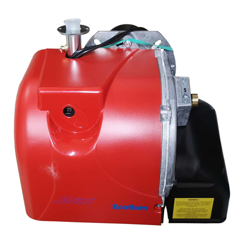
Popular Burner manuals by other brands

TriangleTube PSRKIT11 instructions

TriangleTube

TriangleTube PSRKIT11 instructions

Oilon RP-130 M Operation and maintenance manual

Oilon

Oilon RP-130 M Operation and maintenance manual

Carlin 702G/O instruction manual

Carlin

Carlin 702G/O instruction manual

Riello Gulliver RG3 Installation, use and maintenance instructions

Riello

Riello Gulliver RG3 Installation, use and maintenance instructions

Riello RS 28/M Installation, use and maintenance instructions

Riello

Riello RS 28/M Installation, use and maintenance instructions

Twin Eagles CKLP-TEPB quick start guide

Twin Eagles

Twin Eagles CKLP-TEPB quick start guide

Pelltech PV1000agri user manual

Pelltech

Pelltech PV1000agri user manual

Riello G20 Installation, use and maintenance instructions

Riello

Riello G20 Installation, use and maintenance instructions

Unigas K990A installation manual

Unigas

Unigas K990A installation manual

Mason-Lite MFP39VF Assembly, installation and operation instructions

Mason-Lite

Mason-Lite MFP39VF Assembly, installation and operation instructions

Riello RX 120 S/PV Installation, use and maintenance instructions
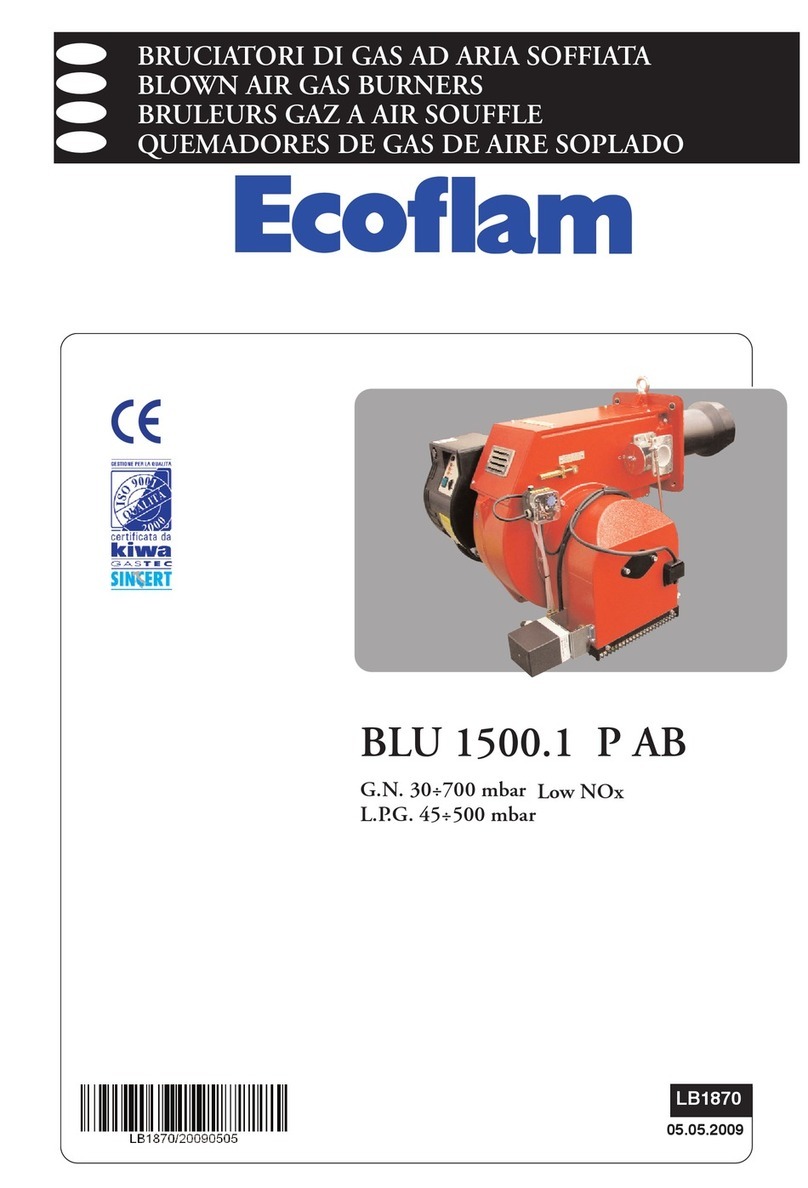
Riello

Riello RX 120 S/PV Installation, use and maintenance instructions
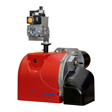
GLOWEN GLRB 1.1 Instructions for use

GLOWEN

GLOWEN GLRB 1.1 Instructions for use

elco VL 4.460 D operating instructions

elco

elco VL 4.460 D operating instructions

baltur GI 350 DSPGN Instruction

baltur

baltur GI 350 DSPGN Instruction

Bentone STG 120/1 Installation and maintenance  instruction

Bentone

Bentone STG 120/1 Installation and maintenance instruction

Unitech T1 installation manual

Unitech

Unitech T1 installation manual

LAMBORGHINI ECO 30 Installation and maintenance manual

LAMBORGHINI

LAMBORGHINI ECO 30 Installation and maintenance manual

Riello 901 T Installation, use and maintenance instructions
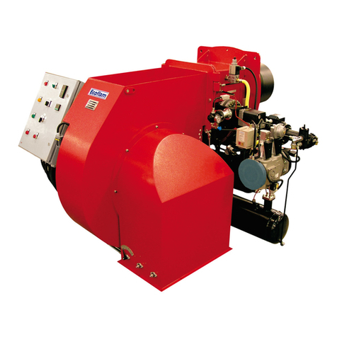
Riello

Riello 901 T Installation, use and maintenance instructions
manuals.online logo
manuals.online logoBrands
  • About & Mission
  • Contact us
  • Privacy Policy
  • Terms and Conditions

Copyright 2025 Manuals.Online. All Rights Reserved.