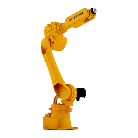
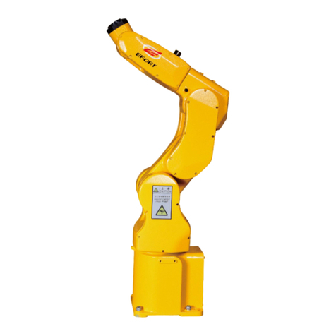
EFORT ER6-1400 User manual

ER6-1400 Quick Operation Manual
for Industrial Robot
EFORT Intelligent Equipment Co., Ltd
Service Hotline(Tel):+86-400-0528877

I
Statement
Thank you for purchasing EFT robot products. In order to ensure that the
products have been set correctly, please read this operation manual carefully
before using this product. The contents mentioned in this statement and the
manual are related to your personal and property safety. If you do not follow the
instructions and warnings in the manual or operate without authorization, it may
cause personal injury to you and the people around you or property damage to
the robot or other objects around you. This statement and manual are the latest
version of this batch of products before leaving the factory. Please visit
www.efort.com.cn Official website for updated information.
This manual is only used as a guide for the normal operation of the product.
During the use of the product, EFT will not be liable for personal injury and
property loss caused by other reasons except product defects. EFORT company
solemnly suggests that: personnel participating in robot operation, teaching,
maintenance, repair, spot inspection and other related activities should not be
given permission to operate the robot before completing the training courses
prepared by EFORT company.
Version: V 1.0

ER6-1400V1.01 Industrial Robot Quick Operation Manual
II
contents
CHAPTER 1 SAFETY....................................................................................................... 4
1.1 SAFETY INSTRUCTIONS.......................................................................................................4
1.2 SAFETY GUIDELINES.........................................................................................................4
CHAPTER 2 HANDLING AND INSTALLATION.......................................................................7
2.2 BASIC DESCRIPTION...........................................................................................................7
2.2.1 unpacking list...................................................................................................... 7
2.2.2 Preparation work before installation................................................................... 8
2.2.3 Robot storage environment................................................................................. 8
2.2.4 Robot operation environment..............................................................................9
2.2.5 Start robot in cold environment...........................................................................9
2.2.6 Table of robot performance parameters.............................................................. 9
2.2.7 Robot workplace............................................................................................... 11
2.3 HANDLING........................................................................................................................12
2.3.1 Precautions for robot handling..........................................................................12
2.3.2 Robot body handling.........................................................................................13
2.3.3 Robot control cabinet handling......................................................................... 15
2.4 INSTALLATION.................................................................................................................. 16
2.4.1 Setting of safety bar.......................................................................................... 16
2.4.2 Robot installation method................................................................................. 16
2.4.3 Ground installation............................................................................................17
2.4.4 Bracket installation............................................................................................18
2.4.5 Upside down installation...................................................................................18
2.4.6 Installation site and environment...................................................................... 19
CHAPTER 3 ELECTRICAL CONNECTION................................................................. 24
3.1 ROBOT POWER SUPPLY..................................................................................................... 24
3.2 ROBOT POWER,SIGNAL AND GROUNDING CABLES.......................................................... 25
3.3 CONTROLLER LOCAL IO DEFINITION................................................................................26
3.4 IO MODULE EXPANSION................................................................................................... 28
3.4.1 Controller local IO extension............................................................................28
3.4.2 Controller remote IO extension.........................................................................29
3.5 IO SETTINGS.................................................................................................................... 30
3.5.1 Update IO module.............................................................................................30
3.5.2 Remote IO configuration.............................................................................31
3.5.3 IO Free configuration........................................................................................33
3.5.4 Analog IO configuration.............................................................................39
3.6 INTRODUCTION OF EXTERNAL EMERGENCY STOP............................................................ 41
3.6.1External emergency stop.................................................................................... 41
3.6.2 Emergency stop output dry contact...................................................................42

ER6-1400V1.01 Industrial Robot Quick Operation Manual
III
3.6.3 Safety door X12................................................................................................ 42
CHAPTER 4 QUICK OPERATION.................................................................................43
4.1 TEACHING PENDANT........................................................................................................ 43
4.1.1 About teaching pendant.....................................................................................43
4.1.2 Function area and interface............................................................................... 44
4.1.3 How to hold the teaching pendant...........................................................46
4.2 POWER ON AND START..................................................................................................... 47
4.3 JOG OPERATION................................................................................................................ 47
4.3.1 What is Jog operation..............................................................................47
4.3.2 Points for attention on jogging operation.......................................................47
4.3.3 Start jogging operation......................................................................................47
4.3.4 Joint coordinate system - jogging operation.................................................. 48
4.4 SHUT DOWN AND POWER OFF.......................................................................................... 49
CHAPTER 5 COMMON FAULTS AND INVESTIGATION METHODS DURING INSTALLATION.50

4
Chapter 1 Safety
1.1 Safety instructions
According to the relevant laws, regulations and regulations of the state and the local government,
safety prevention is the most basic concern when using industrial systems including industial robots.
In the event of personal injury and property loss caused by the use of robots, the factory using
robots is responsible. Therefore, in addition to understanding this manual and relevant information, all
laws and standards concerning health and safety must be understood and must be observed.
For safety, it is only the minimum requirement to comply with the provisions of this manual and
other EFFORT company manuals. As a general rule, the safety related information recorded in this
manual does not fully cover all aspects of robot application system. Therefore, when using robots,
necessary safety measures should be taken and strictly observed according to the actual situation of the
system and its application environment.
Operators must carefully read the following information, especially the safety measures listed in
this chapter.
Users of the EFORT industrial robots shall be responsible for ensuring compliance with
applicable safety laws and regulations in the country/district and that the necessary safety equipment
used to protect the operator of the robot system is designed reasonably and installed correctly. Robot
operators must be familiar with the operation and handling of industrial robots as described in the
following applicable documents:
ER Series Robot Safety Manual
Electrical Operation and Maintenance Manual for Medium and Small Payload Industrial Robot
ER Series Robot Operation Manual
Mechanical Use and Maintenance Manual for ER Series Industrial Robot
Quick Start Manual for ER series Industrial Robot
This manual contains all the safety instructions contained in the product manual for robots and
controllers. The robot system shall be designed and manufactured very well in order to safely enter all
areas necessary for intervention during operation, adjustment and maintenance. For the situation that it
is necessary to work in the safe protection space, it is necessary to ensure safe and sufficient access to
the working position. Users shall not be exposed to hazards, including slip, trip and fall hazards.
1.2 Safety guidelines
Prohibited acts
1. Do not change or remove the protective device and safety device of industrial robot at
will.
2. In case of waterlogging, do not touch the robot. First cut off all power and drain the site.
3. The operation of industrial robots can only be carried out by professionals who have
received sufficient training and guidance (including those who have read this manual).
4. Make sure that the area around the emergency stop equipment is unblocked. Do not pile

ER6-1400V1.01 Industrial Robot Quick Operation Manual
5
up sundries before the emergency stop equipment, which will hinder the use of the
equipment in emergency.
5. It is not allowed to use unsuitable materials, adjust and modify the robot improperly.
6. Unauthorized personnel or personnel who have not received training in the use of the
robot and are aware of the existing risks shall not operate the robot.
7. Do not use the robot when:
Exposure of robot components
The safety device is disabled
When all or part of the fuse and / or mechanical equipment is disabled
The processed materials do not meet the requirements
No more than one person is allowed to use the machine at the same time
8. It is strictly forbidden to use the robot in violation of the above requirements, especially
the use of nonoriginal accessories.
9. Do not move the safety protection device. It is the user's responsibility to ensure that the
safety protection device is fixed and operated orderly.
10. The safety device can only be moved during maintenance, but the operation procedures
of the maintenance personnel must be followed, and the operation must be carried out under
the condition of ensuring the safety of the robot.
Coercive measures
1. Make sure that no one is in the danger area before starting the machine.
2. All operators must receive special training on the use and maintenance of industrial
machines.
3. The foreman shall continuously monitor to ensure the normal operation of all procedures
and ensure the correct application of safety protection procedures.
4. Carry out maintenance according to the maintenance requirements in this manual to keep
the industrial robot clean and tidy.
5. Appropriate tool kits should be prepared to store cleaning tools and maintenance tools;
personnel must wear the personal protective equipment.
6. In addition to these instructions, the trial users must comply with current health and
safety regulations.
7. When the robot fails, or is suspected to be damaged, and the machine does not work or
makes abnormal noise, the machine should be stopped.
8. Once you find a fire in the machine (regardless of the size of the fire), you should
immediately call the police and find a professional team to put out the fire.
9. When the machine is running, the control cabinet door must be closed all the time and
cannot be opened. The key of control cabinet must be kept by electrician.
10. When operating with the mode of power-on, personnel are not allowed to enter the
safety protection area.
11. Before the automatic mode is turned on, all the temporarily disabled safety functions
must be restored to the normal working state.

ER6-1400V1.01 Industrial Robot Quick Operation Manual
6
warning
1. The release of gravity and brakes may cause a fall hazard.
2. When the safety protection device is inspected, it may cause danger to the maintenance
personnel because the safety protection device cannot work. Therefore, the maintenance
personnel must be very careful and take all kinds of protective measures.

ER6-1400V1.01 Industrial Robot Quick Operation Manual
7
Chapter 2 handling and installation
2.1 Overview
This chapter contains assembly instructions and information about installing the ER7-700 (ER2-S
cabinet) industrial robot on the job site.
Before starting any installation work, it is very important to check all safety information first! Be sure
to read the safety manual of EFORT robot carefully, as well as the first chapter of this manual. There are
several general safety aspects that must be read in full, as well as more specific safety information about the
dangers and safety risks encountered in performing the operation procedures.
2.2 Basic Description
2.2.1 unpacking list
1. Before unpacking, please confirm whether the outer package of the product is in good condition.
2. After unpacking, please confirm whether the robot accessories are complete and whether the model
is consistent with the order. In case of missing or wrong parts, please contact the supplier in time.
Table 2-1 robot packing list
开箱清单
Name
Type
Qua
ntity
Unit
Remark
Robot body
ER6-1400V1.01
1
PC
Control cabinet
EC-M6
1
PC
Teach pendant + teach
pendant line
11500010563
1
PC
control cabinet –robot
body power line
10900021800
1
SET
Standard length 8m,Support
regular customization 12m、
16、20m
control cabinet - robot
body encoder line
10900021801
1
SET
Standard length 8m,Support
regular customization 12m、
16、20m
control cabinet – line
for body- ground wire
connecting
10900021958
1
SET
Standard length 8.5m,
Support regular
customization 12.5m、16.5、
20.5m
power aerial plug for
control cabinet
10900001237
1
PC
has been installed on the
control cabinet
10900001229
1
PC
10900001236
1
PC
dust cover of
10900001113
2
PC
has been installed on the

ER6-1400V1.01 Industrial Robot Quick Operation Manual
8
power aerial plug
control cabinet and the body
10900001122
2
PC
accessories (bracket,
pin)
\
1
SET
has been installed on the
robot body
Instruction QR code
\
1
PC
Safety door bridge
connector
10900020261
2
PC
Customers prefer
Note: the above is the standard configuration list, excluding customized models.
2.2.2 Preparation work before installation
This section is intended for the first time to open the box and install the robot. It also contains useful
information needed in the process of reinstalling the robot later.
Before the robot installation, the following inspection items shall be carried out:
Table 2-2 Precautions before installation
1
Visually check the robot to ensure it is not damaged.
2
Ensure that the lifting device used is suitable for handling the specified robot
weight.
3
If the robot is not directly installed, it must be stored according to the
requirements of the robot storage environment.
4
Ensure that the expected operating environment of the robot meets the
requirements of the robot operating environment.
5
Before transporting the robot to its installation site, please ensure that the site
meets the ground installation requirements.
6
Before moving a robot, please check the stability of the robot.
7
After these prerequisites are met, the robot can be transported to its installation
site as described in the following sections。
2.2.3 Robot storage environment
The following table shows the allowed robot storage conditions:
Table 2-3 Robot storage environment
Parameter
Value
Minimum ambient temperature
-40℃

ER6-1400V1.01 Industrial Robot Quick Operation Manual
9
Maximum ambient temperature
+55℃
Maximum ambient humidity
93% RH, no condensation(40℃)
2.2.4 Robot operation environment
The following table shows the allowed robot operation conditions:
Table 2-4 Robot operation environment
Parameter
Value
Minimum ambient temperature
0℃
Maximum ambient temperature
+45℃
Maximum ambient humidity
80% RH, no condensation(40℃)
2.2.5 Start robot in cold environment
This procedure describes how to start a robot in a cold environment. The temperature rise rate must be
adjusted according to the ambient temperature and the operating procedure used. The following table shows
an example of speed adjustment methods:
Table 2-6 Working cycle of starting the robot in cold
cycle
speed percentage
3 working cycles
20
5 working cycles
50
5 working cycles
80
5 working cycles
100
2.2.6 Table of robot performance parameters
The following table shows the performance parameters of the robot
Table 2-6 parameters of robot
Robot Modal
ER6-1400V1.01
Type of Movement
Joint
Control axis
6 Axis
Maximum
operating speed
J1 axi
175°/s
J2 axi
175°/s
J3 axi
185°/s
J4 axi
330°/s
J5 axi
360°/s
J6 axi
600°/s

ER6-1400V1.01 Industrial Robot Quick Operation Manual
10
The following
table shows
the
performance
parameters of
the control
cabinet
Table 2-7 control cabinet parameters
Control cabinet
model
EC-M6
IP class
IP54, heat-radiating unit IP30
IP port
16 digital inputs / 18 digital outputs
(customer available, support expansion)
Communication
mode
TCP/IP、Modbus-TCP、CAN open、ProfibusDP、
EtherCAT
Power supply
3×380V±10%,50/60Hz
Dimension
W522mm×D560mm×H1165mm
Weight
125kg
Ambient
temperature
0℃~45℃
Ambient
humidity
80%RH,no condensation(40℃)
Maximum range
of motion
J1 axi
±165°
J2 axi
+75°/-135°
J3 axi
+170°/-83°
J4 axi
±180°
J5 axi
±130°
J6 axi
±360°
The maximum active
radius
1433mm
The maximum load of
wrist
6 kg
Installation conditions
ground installation and
suspension installation
Degree of protection
IP65(wrist part) / IP54(other
part)
The repeat accuracy
±0.05mm
The body weight
145kg

ER6-1400V1.01 Industrial Robot Quick Operation Manual
11
2.2.7 Robot workplace
图2-1 ER6-1400V1.01 robot motion range diagram
Note: the workspace shown in this figure is the maximum that can be reached in theory, and the actual
operation will be affected by the installation mode. In the actual use, please consider the impact of the

ER6-1400V1.01 Industrial Robot Quick Operation Manual
12
installation mode on the workspace.
2.2.8 Working space of control cabinet
Outline dimension of control cabinet for medium and small payload type(unit:mm)。
Figure 2-2 dimensions of robot control cabinet
When placing the control cabinet, please do not block the air vent of the electric cabinet, which will
affect the heat dissipation of the electric cabinet. Please reserve more than 150 mm space around the
electric cabinet.
When installing the robot, make sure it can move freely in the whole workspace. If there is a risk of
collision with other objects, the working space can be limited by the adjustable limit block of hardware and
the safe working space of software.
2.3 Handling
2.3.1 Precautions for robot handling
The following contents are the precautions in robot handling operation. Please fully understand the

ER6-1400V1.01 Industrial Robot Quick Operation Manual
13
following contents before safe operation:
The handling of robots and control devices must be carried out by qualified personnel for
hook, lifting operation, forklift, etc. If the operators do not master the correct skills to
carry out the operation, it may lead to overturning, falling and other accidents.
When handling the robot and control device, please confirm the weight and steps
according to the method recorded in the manual. If the operation cannot be carried out
according to the specified method, the robot and control device may overturn or fall
during the handling process, resulting in accidents.
When handling and installing, pay attention to avoid damaging the wiring. In addition,
after the assembly of the device, protective measures such as covering with protective
cover should be taken to avoid damage to wiring by operators and forklifts.
2.3.2 Robot body handling
1) Handling method 1
When hanlinging the robot, first set the robot according to the posture shown in Fig. 2-3 and 2-4, then
install 4 M10 lifting ring screws on the main frame and lift it with four steel cables. It is suggested that the
length of the steel cable should not be less than 3m, and rubber hose should be put on the contact part
between the steel cable and the main body of the robot for protection.
Note: in Fig. 2-3 and Fig. 2-4, there are no other devices installed on the end effector and manipulator,
so please pay more attention once other devices are installed.
2)Handling method 2
Set the robot to the posture shown in the table below and use the forklift to carry.
The angle of each axis of the handling attitude and posture is set as follows:
Table 2-8 angle setting values of each axis of handling attitude
Model
Position
1 axis
2 axis
3 axis
4 axis
5 axis
6 axis
ER6-1400V
1.01
Joint
angle/°
0
+74.5
-74.5
﹢90
﹢90
0

ER6-1400V1.01 Industrial Robot Quick Operation Manual
14
Figure 2-3 schematic diagram of lifting hanling
Figure 2-4 schematic diagram of forklift handling

ER6-1400V1.01 Industrial Robot Quick Operation Manual
15
When handling, please be sure to install and use the fixed fixture!
When using other handling methods instead of crane and forklift, please note that the arm
and motor of the robot cannot be affected by external force!
After unpacking, be sure to remove the handling fixture and rubber pad!
Due to the need of robot handling in the future, please keep the fixture properly!
2.3.3 Robot control cabinet handling
1、Handling method 1:
It is recommended to use the 4 casters at the bottom of the control cabinet to move the control cabinet
(2 universal wheels and 2 fixed wheels. After unlocking the universal wheels, you can directly push the
control cabinet to the target position, and then lock the universal wheels for fixation). Please make sure that
the control cabinet is not inclined during transportation, and it is forbidden to stack the control cabinet.
2、Handling method 1:
If it is necessary to lift the robot control cabinet, as shown in the figure, the top of the control cabinet
is equipped with two M10 lifting ring screws, which are lifted by two soft lifting belts. It is suggested that
the length of the soft lifting belt should not be less than 2m, and rubber hose should be put on the contact
part between the soft lifting belt and the main body of the robot for protection.
Figure 2-5 lifting diagram of robot control cabinet
Weight of control cabinet
125kg
Two 100kg soft lifting belt,
do not use steel cable

ER6-1400V1.01 Industrial Robot Quick Operation Manual
16
2.4Installation
1. Set security bar
Otherwise, personal injury, equipment damage and other accidents may occur.
The robot should be placed in a position where the tool and workpiece tip of the robot
arm will not touch the safety bar even if the robot arm reaches the longest.
Otherwise, personal injury and equipment damage may occur.
2. The robot cannot be electrified and operated if it is not fixed.
Otherwise, accidents such as dumping, personal injury and equipment damage may
occur.
3. When choosing the installation method of upside down and wall hanging, it should be
fixed on the ceiling and wall with sufficient strength, and the treatment scheme of
preventing falling should also be considered.
Otherwise, personal injury, equipment damage and other accidents may occur.
2.4.1 Setting of safety bar
The national standard of the People's Republic of China (GB11291.2-2013): Robot and Robot
Equipment and Safety Requirements for Industrial Robots Part 2
:
Robot system and Integration should
be observed. Section 5.4 the robot movement restriction stipulates that "the design and integration of
robot equipment shall reduce the situation that personnel may be exposed to danger". Section 5.4.2 the
provisions for establishing safety protection space and limited space “the safety protection space shall
be established through surrounding protection. The location and layout of the machine and the hazards
within the safety protection space shall be fully considered in the establishment of safety protection
space”. Section 5.10 safety protection regulations:“when the design cannot remove the danger or cannot
reduce the risk sufficiently, then the safety protection shall be applied. Access to hazardous areas shall be
protected by safety guards such as guards and protection devices”
In order to avoid equipment damage and personal injury to the operator and surrounding personnel
during the operation of the robot, please set up the safety bar (with interlocking door and other safety
settings)!
Note: GB11291.2-2013 is equivalent to ISO 10218-2:2011
2.4.2 Robot installation method
The robot installation, especially the fixed base and the foundation, can bear the dynamic load of the
robot when the robot is accelerated and decelerated and the static weight of the robot and the clamp. In
addition, when the mounting surface of the robot is not flat, it may deform the robot and affect its
performance.
Please ensure that the flatness of robot installation is below 0.5mm. The dimensions of the base
installation interface are shown in Figure 2-6 as follows:

ER6-1400V1.01 Industrial Robot Quick Operation Manual
17
Figure 2-6 dimensions of robot base
2.4.3 Ground installation
The ground installation requires that the concrete foundation is firm.The strength grade and bearing
capacity meet the relevant quality specifications. The concrete thickness shall not be less than the landfill
depth of chemical bolts, and the effective range shall completely cover the fixed bottom plate, so as to
ensure the safety and reliability of the bottom plate installation. The concrete specifications refer to code
for design of concrete structures GB 50010-2010 (2015 Edition) and GB 50010-2010 standard for
performance test methods of mechanical properties of ordinary concrete, and the strength grade refers to
C20 / C25.
Table 2-9 parts required for robot fixation
Name
Specification
quantity
bottom plate
thickness≥30mm
1
reference area(600mm×600mm)
Chemical bolt
group
Above M16,strength grade≥4.8
8
Set screw
M16×45,strength grade 12.9
4
Parallel pins
with internal
thread
M12x45
2
When installing on the ground, first fix the bottom plate on the ground. We recommend that the
thickness of the bottom plate should be more than 30mm, and use 8 chemical bolts above M16 to fix the
bottom plate on the ground. The base of the robot is firmly fixed on the base plate through its four
mounting holes with M16 socket head screws of strength grade 12.9 (the screw length must ensure that the
screw length reaches 1.5 times of the nominal diameter of the thread). In order to prevent the socket head
screws from loosening during the operation of the equipment, the M12 parallel pins with internal thread are
installed at the same time.Please fully fix and prevent loosening according to the method of "robot
installation example" in Figure 2-7 below.

ER6-1400V1.01 Industrial Robot Quick Operation Manual
18
Figure 2-7 "example of robot installation"
2.4.4 Bracket installation
When the height of the bracket is less than 600mm, its fixing mode is similar to the ground installation
mode, which is divided into two parts: robot base installation, bracket and ground installation.
When the height of the bracket is more than 600mm, the connection strength between the bracket and
the ground should be strictly checked to ensure that the connection between the bracket and the ground is
safe and reliable.
The specification, quantity and embedded depth of chemical bolt group can be
increased appropriately;
Improve the strength of concrete foundation. The strength of concrete foundation is
higher than that of corresponding chemical bolt components;
2.4.5 Upside down installation
In order to ensure safety, the following precautions should be taken during upside down and wall
mounted installation:
1. Install fall protection device, as shown in Figure 2-8 below;
2. Grade 12.9 strength screws shall be used for connection, and the tightening torque of screws shall
meet the preload requirements of screws of this specification!
Warning
Too long or too short screw for fixing robot base will cause bad fixing accident!
The connection strength of chemical bolts depends on the strength of concrete. When the
strength of concrete is insufficient, it can be strengthened by the following methods:
1. Increase the number of chemical bolt group;
2. Increase the embedded depth of chemical bolts;

ER6-1400V1.01 Industrial Robot Quick Operation Manual
19
Figure 2-8 Upside down installation
2.4.6 Installation site and environment
The robot shall be able to keep normal when used, transported and stored under specified
environmental conditions, and its performance shall meet the requirements.
Table 2-10 table of robot environment parameters
Robot environmental conditions
environmental
conditions
working conditions
storage and transportation
conditions
Ambient
temperature:
0-45℃
-40-55℃
Relative humidity
≤80%(40℃)
≤93%(40℃)
Atmospheric
pressure
86-106 KPa
Vibration
less than 0.5G,4.9m/s2
Other
non corrosive gas (note)
Note: For robots to be used, if there is strong vibration in the use environment, there is a lot of dust,
cutting oil splashing, or other objects, please contact the after-sales service department of the company to
protect the robot parts by using robot sleeve or other means.
Table of contents
Other EFORT Robotics manuals

EFORT
EFORT ER15-1400 User manual

EFORT
EFORT ER15-1400 User manual

EFORT
EFORT ER10-1600 User manual

EFORT
EFORT ECR5 User manual

EFORT
EFORT ER20-1700 User manual

EFORT
EFORT ER15-1400 User manual

EFORT
EFORT ER130-4-2800 User manual

EFORT
EFORT ER3-600 User manual

EFORT
EFORT ER10-1600 User manual

EFORT
EFORT ECR5 User manual

EFORT
EFORT ER15-4-1600 User manual

EFORT
EFORT ER15-4-1600 User manual

EFORT
EFORT ER20-1100 User manual

EFORT
EFORT ER180-4-3200 User manual

EFORT
EFORT ER20-1700 User manual

EFORT
EFORT ER12-4-2000 User manual

EFORT
EFORT ER7-700 User manual

EFORT
EFORT ER6-2000 User manual

EFORT
EFORT ECR5 Instruction manual

EFORT
EFORT ER3-600 User manual