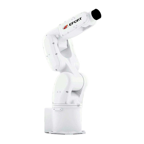
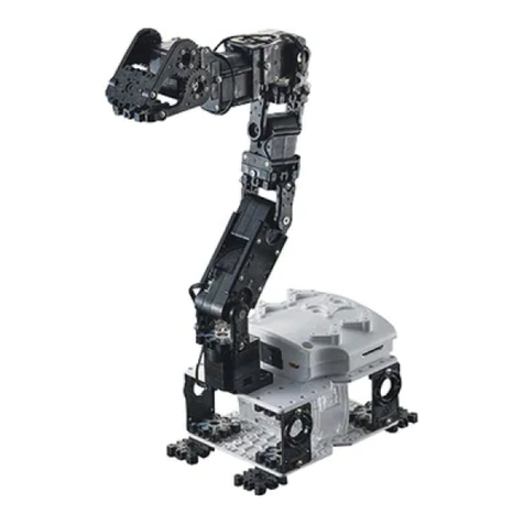
EFORT ECR5 User manual

ECR5 Collaborative Robot
------------------User Manual
Please read this manual carefully before usage.

EFORT INTELLIGENT EQUIPMENT CO.,LTD.
ECR5 User Manual
(Mechanical and Electrical Part)
Version:V1.1
------(Tel):4000528877---

Thank you for purchasing EFORT robot products. In order to ensure
that the ECR5 products have been set correctly, please read this operation
manual carefully before using. The contents mentioned in this
announcement and the manual are related to your personal and property
safety. If you do not follow the instructions and warnings in the manual or
operate without authorization, it may cause personal injury to you and the
people around you or property damage to the robot or other objects
around you. This announcement and manual are the latest version of this
batch of products before delivery. Please visit www.efort.com.cn for
updated information.
This manual is only used as a guide for the normal operation of the
product. During the use of the product, EFT will not be liable for personal
injury and property loss caused by other reasons except product defects.
Our company seriously suggests that: the personnel who participate in
robot operation, teaching, maintenance, repair, spot inspection and other
related activities should not be given permission to operate the robot
before completing the training courses prepared by company.

Catalog EFORT INTELLIGENT EQUIPMENT CO.,LTD.
I
..................................................................................................................................................................... 1
..................................................................................................................................................3
1.1 Introduction ........................................................................................................................................... 3
1.2 Warning Signs ....................................................................................................................................... 3
1.3 Attention Notice ....................................................................................................................................4
1.3.1 Instruction ................................................................................................................................. 4
1.3.2 Personnel Security.................................................................................................................. 8
1.4 Risk Assessment ....................................................................................................................................9
1.5 Responsibility Norm ............................................................................................................................9
1.6 Application Scenario .........................................................................................................................10
1.7 Emergency Stop and Emergency Handling ............................................................................. 10
1.7.1 Emergency-Stop Device .................................................................................................. 10
1.7.2 Return to Normal from Emergency ...............................................................................11
1.7.3 Forced Movement after Power Cut-off .........................................................................11
1.7.4 Release the Brake after Power Cut-off ......................................................................... 11
................................................................................................................. 12
2.1 Outlines................................................................................................................................................. 12
2.2 Manipulator .........................................................................................................................................12
2.2.1 Tool Flange ...........................................................................................................................13
2.3 Control Cabinet ..................................................................................................................................15
2.4 Teach Pendant .....................................................................................................................................17
........................................................................................................19
3.1 Outlines................................................................................................................................................. 19
3.2 Mechanical Interface ........................................................................................................................21
3.2.1 Base Installation Size ...........................................................................................................21
3.2.2 Control Cabinet Installation Size ....................................................................................21
3.2.3 End Effector Installation Size .......................................................................................... 22
3.3 Electrical Interface........................................................................................................................ 23
3.3.1 Control Cabinet Electrical Interface............................................................................. 23
3.3.2 Connection between the Control Cabinet and the manipulator ..........................32
3.3.3 Tool Flange Electrical Interface ...................................................................................... 32
............................................................................................................................. 37
4.1 Lifting and Handling ........................................................................................................................37
Catalog EFORT INTELLIGENT EQUIPMENT CO.,LTD.
II
......................................................................................................... 38
5.1 Maintenance and Repair ............................................................................................................. 38
5.1.1 Regular Maintenance .......................................................................................................... 38
5.1.2 Joint Slip Compensation .................................................................................................... 38
5.2 Disposal ..............................................................................................................................................39
.......................................................................................................................40
6.1 Product Quality Assurance ............................................................................................................ 40
6.2 Disclaimers...........................................................................................................................................40
............................................................................................................................ 42
7.1 Robot Power-on ..................................................................................................................................42
7.1.1 Check before Power -on ..................................................................................................... 42
7.1.2 Power -on ................................................................................................................................. 42
7.2 Robot Power-off ................................................................................................................................. 42
7.2.1 Check before Power-off...................................................................................................... 42
7.2.2 Power -off.................................................................................................................................42
7.3 Drag Teaching.....................................................................................................................................42
7.3.1 Point Drag Teaching Procedure.......................................................................................42
7.3.2 Path Drag Teaching Procedure........................................................................................43
..............................................................................................................................................................44
A Mounting Screw Tightening Torque..............................................................................................44
A.1 Tightening Torque of Hexagon Socket Screw ............................................................... 44
B Technical Terms .................................................................................................................................45
C Stopping Time and Stopping Distance......................................................................................46
D Maximum Payload ........................................................................................................................... 46

Preface EFORT INTELLIGENT EQUIPMENT CO.,LTD.
1
Thank you for purchasing our 5kg level 6-DOF collaborative robot ECR5
打包清单:
ECR5 is a collaborative robot independently developed by
EFORT. The whole machine adopts modular design, and there is
no mechanical limit for the joints. The theoretical limit can reach
±360 degrees(see the technical specifications for software
limit),The dead weight of the manipulator arm is 20.5kg, and the
rated load is 5kg,The working range is 928 mm, the installation
size of base is 140 mm, the size of terminal interface is 50 mm,
the operation of terminal function key is simplified, the speed of
maximum tool side runs at 2.5 m/ s, and the repeated positioning
accuracy is ±0.03 mm.
ECR5 is designed based on the modularity concept and
adopts an open software architecture, which is characterized by
safe cooperation, light weight and beautiful appearance, simple
programming, convenient mounting and dismounting, and
flexible deployment, combined with sensitive collision detection
function and good drag teaching function, it is a comprehensive
choice of safety and efficiency.
ECR5 is suitable for assembly, testing, loading and
unloading, sorting, handling, packaging, palletizing and other
fields in automobile, 3C, food and beverage, medicine, logistics
and warehousing industries.

Preface EFORT INTELLIGENT EQUIPMENT CO.,LTD.
2
Package List:
When you order a complete set of ECR5 cooperative robots, you will receive two
packages:
Package A:length725 mm × width435 mm × height397.5 mm
1 ECR5 manipulator
1 teach pendant (including wiring harness)
Package B:length560 mm × width475 mm × height317.5 mm
1 control cabinet
1 set of manipulator cable
1 set of power supply cable
1 set of CD (User Manual included)
Unpacking Guide:
Please check the package appearance and label content carefully before
unpacking
Fig. 0.1 Illustration of the Packaged Contents of Box A
Fig. 0.2 Illustration of the Packaged Contents of Box B

Safety EFORT INTELLIGENT EQUIPMENT CO.,LTD.
3
1.1 Introduction
This chapter contains important safety information of ECR5 collaborative robot.
Integrators and users must carefully read and understand the operation rules and
safety specifications in this manual. The contents with warning signs should be
mastered and strictly observed.
This chapter involves the safety of personnel and equipment, please read it
carefully.
1.2 Warning Signs
A large number of warning signs are used in this manual to indicate important
information during use. The definition of warning signs is as follows. Please read
them carefully:
Danger!
It means a dangerous situation is about to happen. If no corresponding
preventive measures are taken, it will lead to death or serious physical
injury.
Warning!
It means a dangerous situation may occur. If no corresponding preventive
measures are taken, it will lead to death or serious physical injury.
Caution!
It means a dangerous situation may occur, which will lead to property loss
or minor physical injury if corresponding preventive measures are not
taken.
Caution!
In the absence of warning signs, there is a caution warning, indicating
that dangerous situations may occur. If no corresponding preventive
measures are taken, property damage will be caused.

Safety EFORT INTELLIGENT EQUIPMENT CO.,LTD.
4
1.3 Attention Notice
ECR5 has a wide range of applications. This manual describes the feasible and
prohibited items in use as far as possible, but it can not cover all the applications.
Users should read this manual carefully before use, and fully understand and master
the application safety rules, so as to protect personnel and equipment from damage.
1.3.1 Instruction
When starting the robot system for the first time, the following specifications
should be strictly followed, and other safety related information will be introduced in
the corresponding chapters. However, it is impossible to cover all aspects. In practical
use, specific problems need to be analyzed in different cases.
Danger!
It means that dangerous electrical use may occur, if no corresponding
preventive measures are taken, it will lead to death or serious physical
injury.
Warning!
It means that dangerous electrical use may occur. If no corresponding
preventive measures are taken, it will lead to personal injury or serious
damage to equipment.
Warning!
It means that a hot heating surface may be dangerous. If no corresponding
preventive measures are taken, it will cause personal injury.

Safety EFORT INTELLIGENT EQUIPMENT CO.,LTD.
5
Danger!
1. Please install the robot and related electrical equipment in strict
accordance with the requirements and specifications in this manual;
2. Before putting into production, please conduct a comprehensive safety
inspection on the robot;
3. When using the equipment for the first time, make sure that all parts of
the robot system are intact and safe.Whether the installation and
construction of the equipment comply with the local safety production
rules and regulations, it is necessary to test the safety functions of the
robot and the on-off of each safety signal circuit;
4. The user must ensure the correctness of each robot safety function
parameter setting and the program.The qualified personnel shall check and
ensure that all safety functions can work normally. Only when the state of
the robot system reaches the security level required by the application can
it be enabled to start.
Danger!
1. The installation and debugging of the robot should be carried out by
professionals;
2. When the robot system is completed, it is necessary to conduct a
comprehensive risk assessment again and keep the record file.

Safety EFORT INTELLIGENT EQUIPMENT CO.,LTD.
6
Danger!
1. The setting and modification of the safety function parameters of the
robot should be carried out by authorized professionals. Passwords or other
protective measures should be used to prevent unauthorized personnel from
editing and modifying the safety function parameters. After editing and
modifying the safety function parameters, it is necessary to
comprehensively analyze the possible impact;
2. In the event of an accident or other emergency, the robot can be stopped
by pressing the emergency stop button. After the e-stop button is pressed,
the power supply of the robot arm will be cut off;
3. ECR5 itself contains a brake, but there is a gap in the brake. After the
power cutting-off of the robot, the brake system can keep all joints of the
robot within a certain range of motion (within 0.5 degrees). Do not turn on
or off the power frequently;
4. ECR5 has the function of collision detection, and can set the sensitivity.
When the robot is subjected to collision force larger than the set sensitivity,
the robot will stop automatically to prevent personnel and equipment
damage. This function is designed for collaborative applications, which
requires the robot to be in the normal working range, and cooperate with
the use of CRC10 control cabinet. The safety function is developed based
on this control cabinet. If the user configures the control cabinet by
himself, it does not have this function. The risk should be borne by users
themselves.
Warning!
1. When the robot works at a higher speed, it may produce higher heat.
Do not touch the robot directly when the robot is working or just stops
working.
2. There are air inlets and outlets on the side of the controller. Please do
not cover them when placing them, and keep a certain distance from the
obstacles (not less than 20cm) to ensure good ventilation and heat
dissipation.
3. Do not touch the heating element in the controller when the robot is
working or just stops working.

Safety EFORT INTELLIGENT EQUIPMENT CO.,LTD.
7
Warning!
1. Ensure the connection between robot and end effector is tight and
reliable;
2. When changing the installation mode, you need to set the installation
mode in the corresponding interface. The installation mode may affect the
collision detection, drag teaching and other functions. Please operate and
verify the robot carefully at low speed after changing the installation
mode;
3. The smooth and streamlined appearance of ECR5 robot can reduce the
risk of injury from operators in the process of use, but it needs to ensure
that there are no sharp points to reduce the safety risk when installing the
end execution tools and peripheral pipelines or other accessories.
4. Please do not change the robot. If you change the robot without
permission, it may cause unpredictable safety problems. EFORT refuses to
take responsibility for all the consequences arising therefrom.
5. Do not place the robot in a strong magnetic field environment, which
will cause irreversible damage to the robot;
6. Ensure that the installation environment of the robot provides enough
space for the robot to work;
7. When installing or replacing the end effector, it is necessary to
correctly set or calibrate the mass and inertia attributes of the tool end, and
check the program at low running speed. When it comes to collaborative
operation, it is necessary to reevaluate the risk and fully understand the
properties of the installed terminal equipment, taking the potential risks in
operation into full consideration.
8. During transferring and transportation, it’s necessary to make full
protection for the robot to avoid collision and abrasion, and fold it to the
full to reduce the gravity torque/moment and inertia of the robot. If
condition permits, the robot can be motioned into the packing position,
removed and placed in the original packing box for transportation. The
packing box can be equipped with a cushion, which can greatly reduce the
impact in the transportation process to protect the robot.
9. Do not put the robot in the environment of high temperature and
humidity, otherwise the robot may not work normally;
10. Do not use the damaged robot;
11. Before using the robot, please ensure that the power supply of the
electric box and the robot mounting base are fully grounded.

Safety EFORT INTELLIGENT EQUIPMENT CO.,LTD.
8
Caution!
1. The programming of robot needs to be done by professionals. EFORT
shall not be liable for personnel injury and equipment damage caused by
programming error or improper user operation, etc.
When new equipment is added to the robot system, it is necessary to carry
out a systematic and comprehensive inspection on the functions and
programs of the robot, which can reduce the risk of use.
1.3.2 Personnel Security
When using the robot, fully ensure the safety of the operator. Please read the
precautions listed in this section carefully and take appropriate safety measures to
ensure the safety of the operator.
Caution!
1. All operators using ECR5 robot system shall receive and pass training
courses provided by EFORT headquarters or other authorized training
institutions. You should ensure that all operators fully master all safety
specifications of robot operation and are qualified by EFORT.
2. When operating the robot, the operator shall dress in accordance with
the safety regulations, and shall not wear loose clothes, necklaces, jewelry,
etc., the person with long hair shall tie the long hair behind his head to
avoid being intertwined into the mechanical arm.
3. The end of ECR5 is equipped with a status light band, which can
display the running status of the robot. When the status light band is in
yellow, it indicates that the robot is in non-cooperative mode, at this time,
do not touch the robot.
4. When the robot stops at a certain position, it may be the waiting
instruction set by the program, at this time, do not touch the robot.
5. Clear signs should be set around the installation position of the robot to
indicate the normal working range of the robot. In principle, when the
robot is used in the cooperation situation and the mode is on, it is not
necessary to set fences, but it needs to go through a comprehensive risk
assessment.
6. In case of emergency, the end cover of the joint can be dismantled to
rotate the joint (see section 1.7.3 for details) after power cut-off. You can
also rotate the joint with more force without removing the end cover, but
the joint will be damaged.

Safety EFORT INTELLIGENT EQUIPMENT CO.,LTD.
9
1.4 Risk Assessment
In principle, ECR5 collaborative robot can be used without external fence, but the
risk of operation and normal running must be assessed. The risk assessment must be
completed before the robot is put into use. Integrators and users must fully consider
all tasks of the robot in its whole life cycle to measure the risk level and acceptability.
You can start the assessment from the following aspects, but not limited to:
1. The sharp-pointed corners of end effector/work piece may cause injuries to
personnel;
2. Obstacles in the robot workspace may cause injuries to personnel and
equipment;
3. When the robot is running, it may collide with personnel and cause injury;
4. There may be risks when robot operates dangerous articles;
5. Different security parameter settings may have risks in different applications;
6. There is a risk of unreliable installation of the end effector
7. There is a risk when the robot is close to the rigid boundary/obstacle;
When the robot is integrated / applied in non-cooperative situation, the internal
safety mode of the robot can be turned off. If internal security settings fail, integrators
and users should consider additional security devices and assess their security risks.
After changing the configuration and replacing the end effector of the robot, the
risk assessment should be restarted, which should be completed beforehand.
1.5 Responsibility Norm
ECR5 robot can form a complete robotic application with other devices and
actuators. Due to the complexity and diversity of application scenarios, this document
does not include the design, installation and operation of robot application system.
The design of a complete robot application system needs to comply with the
national and industrial regulations of relevant application scenarios, and conduct
sufficient risk assessment (see Chapter 1.4)
ECR5 system integrators should comply with the relevant national regulations for
application design, and complete the risk assessment of the whole application system.
The responsibilities of the system integrator include but not limited to the following:
1. Complete risk assessment of the whole application system;
2. Make sure the user instruction;
3. Make sure the accuracy of equipment design and installation of robot
application system;
4. Ensure the reliability of the software system, and ensure that users will not
change the important security configuration
5. Conduct sufficient operation training for users;
6. Reduce the risk of application system as much as possible;
7. Convey potential risks to users;

Safety EFORT INTELLIGENT EQUIPMENT CO.,LTD.
10
8. Mark relevant signs and communication information of integrators on robots
and auxiliary equipment;
9. Collect and archive all technical documents, including risk assessment and
this manual
Any safety information contained in this manual shall not be regarded as the
guarantee of our company, even if all safety instructions specified in the manual are
followed, injury or damage may still happen.
1.6 Application Scenario
ECR5 belongs to industrial robot, which is intended to be used in industrial
scenes. It can cooperate with the corresponding end effector for handling, loading and
unloading or other general work. In addition, the robot has collaborative properties
and is equipped with a series of cooperative safety functions. It can be used under the
condition of human-computer cooperation, but the risk assessment must be carried out
(see Chapter 1.4) to assess whether the risk of possible injury to personnel and
equipment is within the acceptable range.
ECR5 should be used in general industrial scenarios. Do not use robots in
scenarios that are inconsistent with the proposed applications. Prohibited application
scenarios include but are not limited to the following:
1. Scenarios with explosion risk;
2. Scenarios involving human and animal life, such as medical treatment;
3. Scenarios beyond specifications;
4. Application scenarios in violation of local provisions;
5. Scenarios involving public security;
6. The scenarios of uncontrollable vibration like vehicles, ships, etc;
7. Scenarios applied to walking and climbing tools;
1.7 Emergency Stop and Emergency Handling
The emergency stop equipment is used to stop the operation of the robot in case
of emergency. It can not be used as a risk reduction measure, but as a secondary
protection equipment (refer to IEC 60204-1 and ISO 13850).
1.7.1 Emergency-Stop Device
There is an emergency-stop device on the robot control cabinet and the teach
pendant, namely the E-stop button. If the emergency-stop device needs to be added, it
should meet the requirements of IEC 60947-5-5 and be included in the risk
assessment.
Warning!
When the robot is attached with additional equipment and end effector, if
there is potential risk, it must be connected to the emergency stop circuit.

Safety EFORT INTELLIGENT EQUIPMENT CO.,LTD.
11
1.7.2 Return to Normal from Emergency
The general e-stop device can release the pressing state by rotating the button to
make the robot return to normal state.
1.7.3 Forced Movement after Power Cut-off
In case of emergency, the robot joint can be rotated by exerting larger thrust or pull
force.
1.7.4 Release the Brake after Power Cut-off
In case of power failure and emergency, the robot joint cover can be
disassembled, and then the electromagnet push rod could be pushed inward, as shown
in the direction of the arrow in below figure to release the brake of current joint.
Illustration of releasing
brake of J1-J3 joint
Illustration of releasing
brake of J4-J6 joint
Danger!
This step is simple but crucial. Make sure the danger is completely
eliminated before operation.
Warning!
This situation is only used for emergency and may cause damage to the
equipment.
Danger!
This brake releasing way is only used for emergency. Before operation,
make sure that each joint which is about to release the brake is supported
reliably. Take care of the gravity of the arm, otherwise the arm may rotate
rapidly by gravity, causing injury to equipment and personnel.

Interface and Installation EFORT INTELLIGENT EQUIPMENT CO.,LTD.
12
2.1 Outlines
A complete set of ECR5 robot system consists of a manipulator, a control cabinet
and a teach pendant, as shown in the figure below. They are connected by the
connection cables to realize communication, power supply and other functions.
Fig. 2.1 The Composition of ECR5 Robot System
2.2 Manipulator
The manipulator consists of 6 modular joints, 2 arms, 1 base and 1 tool end flange.
Each joint moves independently, providing 6 degrees of freedom of the manipulator;

Interface and Installation EFORT INTELLIGENT EQUIPMENT CO.,LTD.
13
the base is used to fix and connect the robot; the tool flange is used to install the
end-effector, and provides interface for I/O and communication.
Fig. 2.2 ECR5-Mechanical System
2.2.1 Tool Flange
The tool flange is equipped with 4 quick operation buttons with the following
functions:

Interface and Installation EFORT INTELLIGENT EQUIPMENT CO.,LTD.
14
Fig. 2.3 Buttons in tool flange
Mode Switching: click this button to switch the operation mode of the robot. Normal
mode (off); point drag teaching mode (flashing), path drag teaching mode (always on)
External I / O: click this button to control the switch of IO output of the end flange.
Off (off); on (on)
Teaching Record: in the point drag teaching mode, press this button, the robot will
record the current position point. In the path drag teaching mode, press this button and
the light will be on. Then, the robot will start tracking record. When this button is
pressed again, the blue light will go out. At this time, the controller will stop tracking
record and generate an executable track file. In normal mode, this button does not
work and will always be off.
Drag confirmation / collision recovery: In point drag teaching mode or path drag
teaching mode, when this button is pressed, the red light is on, and the robot can be
dragged. When the button is released, the red light goes out. Then, the robot will not
be allowed to be dragged by the user. In normal mode, if the robot collides and stops,
this light will be on. At this time, press this button to clear the alarm and resume the
movement of the robot after 5 seconds.
The tool flange is equipped with a ring status light, whose status is described as
follows:
Fig. 2.4 Tool Flange Ring Status Light

Interface and Installation EFORT INTELLIGENT EQUIPMENT CO.,LTD.
15
Green (always on): when the robot operates normally in cooperation mode, the ring
status light is green and always on;
Green (breathing): During the drag teaching operation, when the recording point or
track is successful, the ring status light flashes green for 3 seconds;
Yellow (always on): During the warning state of the robot, the ring status light is
yellow and always on. At this time, the operator should check and handle the warning
information;
Yellow (breathing): when the robot operates normally in non-cooperative mode, the
ring status light is yellow breathing, and the operator can not enter the working space
of the collaborative robot at this time;
Red (always on): when the robot is in the alarm or error state, the ring status light is
red and always on. At this time, the operator needs to check and clear the alarm;
Red (breathing):when the robot stops in case of collision, press the collision
recovery button, the ring status light is red breathing, lasting for 5 seconds. At this
time, the operator needs to stay away from the robot, and then the robot gradually
returns to normal operation.
Blue (breathing): it generally happens when the robot is just powered on, indicating
that the robot is powered on successfully, but the communication is not established.
After the communication is established with the controller, the state changes to yellow
breathing.
2.3 Control Cabinet
The control cabinet is the control center of ECR5 robot, which contains controller,
universal IO interface board, switching power supply and safety protection
components. The control cabinet is powered by alternating current with voltage of
127V-240V and frequency of 50Hz-60Hz. The internal switching power supply
supplies the load and robot in the controller cabinet. Therefore, it is necessary to
check whether the connection cable between the robot, teaching pendant and the
controller cabinet is firm enough before use.
There are E-stop switches on the control panel and teach pendant of the controller
cabinet. The user can stop the robot in the shortest time and cut off the power supply
of the robot to protect the safety of personnel and equipment.
Fig. 2.5 Control Cabinet Composition
Other manuals for ECR5
2
Table of contents
Other EFORT Robotics manuals

EFORT
EFORT ER6-1400 User manual

EFORT
EFORT ECR5 Instruction manual

EFORT
EFORT ECR5 User manual

EFORT
EFORT ER10-3-900 User manual

EFORT
EFORT EC2-M User manual

EFORT
EFORT ER15-4-1600 User manual

EFORT
EFORT ER15-1400 User manual

EFORT
EFORT ER20-1100 User manual

EFORT
EFORT ER12-4-2000 User manual

EFORT
EFORT ER3-600 User manual

EFORT
EFORT ER10-1600 User manual

EFORT
EFORT ER180-4-3200 User manual

EFORT
EFORT ER20-1700 User manual

EFORT
EFORT ER130-4-2800 User manual

EFORT
EFORT ER15-1400 User manual

EFORT
EFORT ER210-2700 User manual

EFORT
EFORT ER10-1600 User manual

EFORT
EFORT ER6-2000 User manual

EFORT
EFORT ER15-4-1600 User manual

EFORT
EFORT ER180-4-3200 User manual