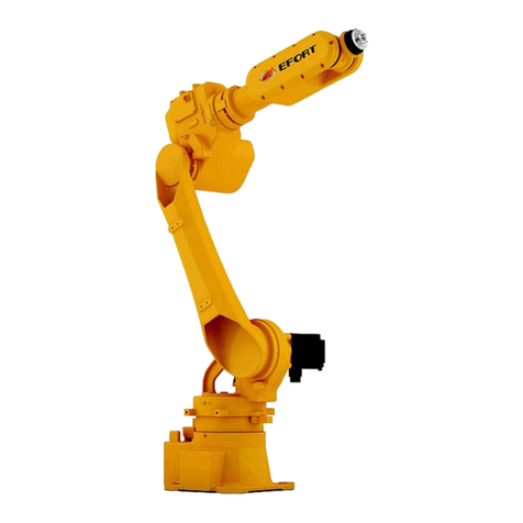
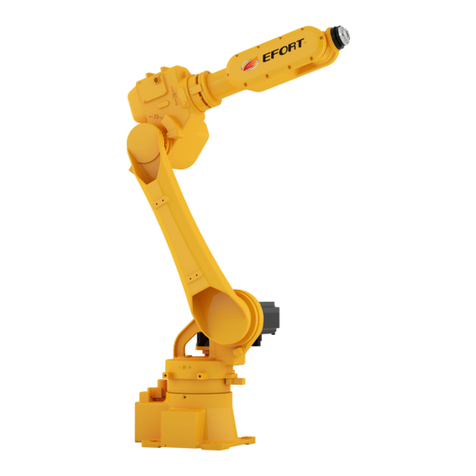
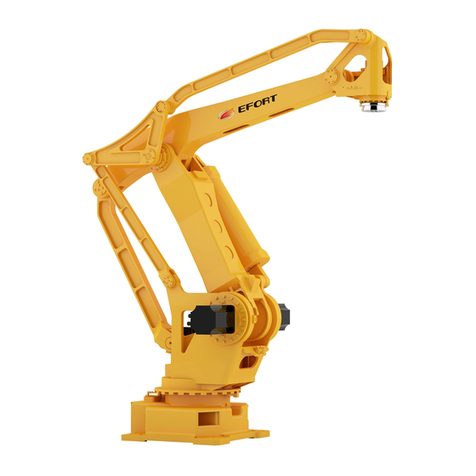
EFORT ER210-2700 User manual

Quick Operation Manual for ER210-2700 Industrial Robot
ER210-2700 Quick Operation Manual
for Industrial Robot
EFORT Intelligent Equipment Co., Ltd.
Service Line(Tel):+86-400-0528877

EFFORT Intelligent Equipment Co., Ltd.
Statement
Thank you for purchasing EFFORT ER210-2700 industrial robot. Please
read the instruction manual before starting to use the robot. The following
contents are directly related to your personal and property safety. Any
misconduct that does not strictly follow the instructions as stated in the manual
may result in physical damage or property loss. The statement and instruction
manual is the latest version for ER210-2700 series. More updates can be found
at www.efort.com.cn.
This manual only serves as the operation guide for ER210-2700 industrial
robots. EFFORT will not be responsible for any physical damage or property
loss that is not caused by the defect of the product. It is strongly recommended
that operators should have received special training before having access to
operation, teaching, repair, maintenance and inspection of the product.
Version:V 1.0

Quick Operation Manual for ER210-2700 Industrial Robot
III
Contents
Chapter One Safety................................................................................................................. 1
1.1 Safety Instructions.............................................................................................................1
1.2 Safety Regulations.............................................................................................................1
Chapter Two Handling and Installing the Robot.................................................................... 3
2.1 General Introduction......................................................................................................... 3
2.2 Basic Description.............................................................................................................. 3
2.2.1 Unpacking........................................................................................................... 3
2.2.2 Preparatory Work before Installation.................................................................. 4
2.2.3 Storage Environment.......................................................................................... 4
2.2.4 Operation Environment.......................................................................................4
2.2.5 Starting the Robot in a Low Temperature........................................................... 4
2.2.6 Robot Performance Parameters...........................................................................5
2.2.7 Robot Motion Space........................................................................................... 6
2.2.8 Control Cabinet Position.....................................................................................7
2.3 Handling the Robot......................................................................................................... 7
2.3.1 Precautions..........................................................................................................7
2.3.2 Handling the Robot Body................................................................................... 8
2.3.3 Handling the Control Cabinet............................................................................. 9
2.4 Installing the Robot.......................................................................................................10
2.4.1 Setting up a Safety Fence..................................................................................10

EFFORT Intelligent Equipment Co., Ltd.
IV
2.4.2 Installation Procedures...................................................................................... 11
2.4.3 Installation Dimensions.....................................................................................11
2.4.4 Installation Surface Precision Requirement......................................................12
2.4.5 Installation Environment...................................................................................14
2.4.6 Integrated Connection Interface........................................................................14
Chapter Three Electrical Connection....................................................................................18
3.1 Robot Power Supply........................................................................................................19
3.2 Connection between the Robot and the Control Cabinet................................................ 20
3.3 Definition of Controller Local IO................................................................................... 20
3.4 IO Module Expansion..................................................................................................... 22
3.4.1 Local IO Module Expansion.............................................................................22
3.4.2 Remote IO Module Expansion..........................................................................23
3.5 IO Configuration............................................................................................................. 25
3.5.1 IO Module Update............................................................................................ 25
3.5.2 Remote IO Configuration................................................................................. 26
3.5.3 Function IO Configuration................................................................................28
3.5.4 Analog IO Configuration.................................................................................. 36
3.6 Introduction to Emergency Stop......................................................................................37
3.6.1External Emergency Stop...................................................................................38
3.6.2 Dry Contact of E-stop Output........................................................................... 38
3.7 Safety Door..................................................................................................................... 39

Quick Operation Manual for ER210-2700 Industrial Robot
V
Chapter Four Teach Pendant Operations............................................................................ 40
4.1 Teach Pendant..................................................................................................................40
4.1.1 About the Teach Pendant...................................................................................40
4.1.2 Function Keys and Interfaces............................................................................41
4.1.3 How to Hold a Teach Pendant?.........................................................................43
4.2 Power On.........................................................................................................................43
4.3 Jogging............................................................................................................................ 43
4.3.1 What is Jogging?...............................................................................................43
4.3.2 Precautions for Jogging.....................................................................................44
4.3.3 Start Jogging..................................................................................................... 44
4.3.4 Joint Coordinate System-Jogging..................................................................... 45
4.4 Power Off........................................................................................................................ 46
Chapter Five Common Faults and Recommended Solutions............................................... 47


Quick Operation Manual for ER210-2700 Industrial Robot
1
Chapter One Safety
1.1 Safety Instructions
According to the national and local laws and regulations, great importance has been attached to safety
protection in the operation of an industrial robot.
The employer of the robot operator is responsible for the physical damage or property loss in case of
an accident. Therefore it is strongly recommended that an operator should fully understand the contents
described in this manual or elsewhere and abide by the health and safety regulations.
For safety reasons, it is the fundamental requirement to abide by the instructions described in this
manual and other manuals of EFORT. The manual serves as a general introduction to safety regulations
which does not take all the aspects into consideration. Therefore, it is highly important for an operator to
take preventative measures according to the application system and the work environment when operating a
robot.
An operator must read the following information carefully and pay special attention to the safety
measures described.
An EFORT industrial robot user should promise to abide by its national or regional safety laws and
regulations and to make sure that the necessary safety protection equipment is reasonably designed and
correctly installed. An operator should get familiarized with the operation procedures described in the
following documents:
ER Series Robot Safety Manual
ER Series Robot Operation Manual
Electrical Operation and Maintenance Manual for ER210-2700 Industrial Robot
Mechanical Operation and Maintenance Manual for ER50-2100 Industrial Robot
Quick Start Manual for ER210-2700 Industrial Robot
The quick start manual includes all the safety descriptions of the robot and controller. The robot should
be well designed and manufactured to ensure that it can enter all the required areas when it is operated,
tested or maintained. The robot should be able to enter the work areas freely if there is a safety prevention
frame. An operator should not be exposed in danger of slipping, stumbling or falling.
1.2 Safety Regulations
Prohibitions
1. Do not change or dissemble the protective equipment or safety equipment arbitrarily.
2. Do not touch a robot in case of waterlogging. Cut off the power and drain off the water.
3. The operation of an industrial robot must be performed by the professionals who have
received sufficient training and guidance and have read this manual thoroughly.
4. The space around the emergency stop equipment must be emptied in case of an
emergency.
5. Improper materials must not be processed with the robot and improper adjustment or
alteration is forbidden.

EFFORT Intelligent Equipment Co., Ltd.
2
6. Those who have not been authorized or who have not received any professional training
regarding the operational risks are not allowed to operate the robot.
7. The robot cannot be operated under the following circumstances:
A robot element is exposed.
The safety equipment is disabled.
The fuse and (or) all or any of the mechanical equipment is disabled.
The workpiece is not qualified.
More than one person is operating the robot at the same time.
8. Any violation of the above mentioned regulations is strictly forbidden. Any attempt to
load an unoriginal accessory is forbidden in particular.
9. Do not attempt to move the safety protection equipment. Users are responsible to make
sure that the safety protection equipment is fixed properly and runs effectively as expected.
10. The safety equipment can only be moved in case of maintenance and the standard
maintenance protocols must be followed to ensure the safety of the robot.
Mandatory Measures
1. Ensure that nobody is in the dangerous areas before booting the robot.
2. Ensure that all the operators have received some professional training in operating
industrial robots.
3. A supervisor should constantly monitor the status of the running programs and to make
sure that the safety protection program is effective.
4. Maintain the robot as instructed in the manual and keep the robot clean and tidy.
5. Pack the cleaning and maintaining tools in a suitable tool box. Any worker should wear
personal safety protection equipment.
6. An operator should follow the current health and safety codes.
7. Stop the robot in case of shutdown, suspected damage, malfunction or abnormal noise.
8. Call the police for professional help in case of fire.
9. The door of the control cabinet should always be lock up and the key should be kept by
an electrician.
10. No one is allowed to enter the safety protection area if the power is on.
11. All the suspended safety functions must be restored to normal before the Auto mode is
switched on.
Warning
1. The release of the gravity braking system might lead to falling.
2. Danger might occur when a repairer performs a regular maintenance for the safety
protection equipment. Therefore, caution and preventative measures are advised.

Quick Operation Manual for ER210-2700 Industrial Robot
3
Chapter Two Handling and Installing the Robot
2.1 General Introduction
This chapter explains how to handle and install the ER201-2700 industrial robot in a workplace. It is
strongly recommended that users should read the Safety Manual of EFORT Industrial Robots carefully and
refer to the first chapter of this manual for the detailed descriptions on safety issues before installation.
2.2 Basic Description
2.2.1 Unpacking
1. Please check whether the packing remains intact or not before unpacking.
2. Please check after unpacking whether all the accessories are complete and whether they match with the
model information on the order list. Contact the supplier if the accessories are not the same as ordered.
Table 2-1 Standard Accessories
Packing List
Name
Model
Quantit
y
Unit
Remarks
Robot body
ER210-2700
1
PC
Control cabinet
EC1-M-02
1
PC
Teach pendant and connection cable
11700010509
1
PC
Control cabinet-robot power cable
10900017168
1
SET
Standard Length: 8 m
Customized Length:
12 m/16 m/20 m
Control cabinet-robot encoder cable
10900017169
1
SET
Standard Length: 8 m
Customized Length:
12 m/16 m/20 m
Control cabinet-robot brake cable
10900017171
1
SET
Standard Length: 8 m
Customized Length:
12 m/16 m/20 m
Control cabinet-robot ground wire
10900021958
1
SET
Standard Length: 8.5
m
Customized Length:
12.5 m/16.5 m/20.5 m
2A Glass fuse
10900001677
1
PC
10A Glass fuse
10900017878
1
PC
32A Pottery fuse
10900024701
3
PC
10A Pottery fuse
10900024705
2
PC

EFFORT Intelligent Equipment Co., Ltd.
4
Accessories(bracket and pins )
\
1
SET
Already installed on
the robot body.
DVD documents
\
1
PC
Note: The packing list contains only the standard articles while the customized articles are not included.
2.2.2 Preparatory Work before Installation
This section contains the information to be used when the robot is newly installed or reinstalled.
Check the following items before installation:
Table 2-2 Checklist before Installation
1
Check whether the robot is intact.
2
Ensure that the lifting equipment is suitable to carry the robot.
3
Store the robot in a required environment if it is not installed.
4
Ensure the expected working environment meets the standard requirement.
5
Ensure the installing ground meets the standard requirement before handling the
robot.
6
Check the stability before moving the robot.
7
Handle the robot to the installation cite if the checklist is completed.
2.2.3 Storage Environment
The following table describes the permitted storage environment for the robot:
Table 2-3 Robot Storage Environment
Parameters
Value
The lowest environment temperature
-10℃
The highest environment temperature
+55℃
Maximum Humidity
93%RH,Dewing Free(40℃)
2.2.4 Operation Environment
The following table describes the permitted operation environment for the robot.
Table 2-4 Robot Operation Environment
Parameters
Value
The lowest environment temperature
0°C
The highest environment temperature
+45°C
Maximum Humidity
80%RH,Dewing Free(40℃)
2.2.5 Starting the Robot in a Low Temperature
This section explains how to start the robot in low temperature. An operator needs to adjust the heating
rate based on the environment temperature and the running programs. The following table describes the
mapping relations between the working cycles and the speed ratio.
Table 2-5 Robot Working Cycles when Started in a Low Temperature
Working Cycles
Speed Ratio

Quick Operation Manual for ER210-2700 Industrial Robot
5
3
20
5
50
5
80
5
100
2.2.6 Robot Performance Parameters
The following table describes the performance parameters for the robot.
Table 2-6 Robot Performance Parameters
The following table describes the performance parameters of the control cabinet.
Table 2-7 Performance Parameters of the Control Cabinet
Control
Cabinet Type
EC1-M-02
IP Rate
IP43
Digital IO
Ports
24 digital input ports and 24 digital output ports
(Expansion Supported)
Model
ER210-2700
Motion Type
Joints
Control Axes
6Axes
Maximum
Motion Speed
Axis J1
100°/sec
Axis J2
90°/sec
Axis J3
95°/sec
Axis J4
110°/sec
Axis J5
105°/sec
Axis J6
200°/sec
Maximum
Motion Rage
Axis J1
±180°
Axis J2
-80°/+60°
Axis J3
-83°/+90°
Axis J4
±360°
Axis J5
±120°
Axis J6
±360°
Maximum Operation Radius (mm)
2674 mm
Maximum Wrist Payload(kg)
210 kg
Installation Requirement
Ground mounting
Prevention Rate
IP65(Dust and water proof)
Repeat Precision
±0.3 mm
Robot body Weight
1110 kg

EFFORT Intelligent Equipment Co., Ltd.
6
Power
3×380V±10%,50/60Hz
Size
W850mm×D480mm×H890mm
2.2.7 Robot Motion Space
Fig. 2-1 Motion Space of ER210-2700 Robot
Note: Fig. 2-1 shows the theoretical maximum motion space of ER210-2700 robot which might be affected
by the way the robot is installed.

Quick Operation Manual for ER210-2700 Industrial Robot
7
2.2.8 Control Cabinet Position
The size of ER210-2700 control cabinet(unit:mm):
Fig. 2-2 Size of Robot Control Cabinet
The ventilation scoop of the control cabinet must not be covered under any circumstance and a
minimum separation space of 150 mm around the cabinet should be guaranteed in order to maximize the
heating radiator efficiency.
Ensure that the robot can move freely within operation space. Limit the robot operation space by
means of adjustable stopper or software control if there is any risk of collision.
2.3 Handling the Robot
2.3.1 Precautions
Please read the following precautions carefully before handling the robot.
Caution
The handling must be performed by a professional with lifting and forklifting work
qualifications. Unprofessional performance might lead to flipping or falling
accidents.

EFFORT Intelligent Equipment Co., Ltd.
8
Caution
Please follow the procedures described in the manual and check whether the weight
of the robot and the control cabinet exceeds the maximum lifting load before
handling the robot. Operations that do not follow these procedures might lead to
flipping or falling accidents.
Caution
Please protect the cables when handling the robot and the control cabinet. Besides,
the cables should be covered by a shield to prevent from accidental damage.
2.3.2 Handling the Robot Body
The angle of each joint is shown in table 2-8 when the robot is handled.
Table 2-8 Joint Angles
Position
J1
J2
J3
J4
J5
J6
Joint angles/°
0°
55°
-75°
0°
-70°
0°
Handle the robot with a forklift is a lifting device is not available.
Fig.2-3 Handling Method
Steel cables are required to go
through the cover pipes for the
purpose of machine protection.

Quick Operation Manual for ER210-2700 Industrial Robot
9
Fig.2-4 Fixing Position of Eye Bolts on the Robot Rotating Base
Caution
Corresponding Fixtures must be used in handling the robot.
Ensure that no pressure is put on the robot arm or electric motor if neither lifting nor
forklifting is applied.
Remove the fixtures and rubber protection after installation.
Store the fixtures in a safe place for future handling.
2.3.3 Handling the Control Cabinet
1. Method One
Fix the control cabinet in the position as shown in fig. 2-5 and lift it with 2 soft cables attached to 2
M10 ring screws on the upper part of the control cabinet. The recommended length of the cables should be
no shorter than 2 meters and rubber hoses should be placed on the cables to prevent from direct contact
with the robot body. Ensure the control cabinet is well balanced and not stacked upon in the process of
transportation. Handle the control cabinet with a forklift if the lifting device is not available.
Fig. 2-5 Lifting Sketch Map for Robot Control Cabinet
2. Method Two
Fixing positon of eye bolts
(4-M20)
Eye bolts cannot be
replaced by
self-tapping bolts
(4-M20)
2 soft cables with minimum bearing
load of 200 kg and steel cables are
strictly forbidden.

EFFORT Intelligent Equipment Co., Ltd.
10
Handle the control cabinet with a forklift if the lifting equipment is available. Please refer to the
recommended fork positions under the control cabinet as shown in fig. 2-7.
Fig. 2-6 Forklifting Sketch Map for Robot Control Cabinet
2.4 Installing the Robot
Danger
1. Set up a safety fence to prevent from accidents leading to physical injury or
property damage. The robot should be placed in a position from which the end tool or
the sharp end of a workpiece can never reach the safety fence even if the robot arm is
extended to its reach limit.
2. Neither the power should be switched on nor should any operation be performed
until the robot has been properly fixed. Otherwise, accidents such as flipping,
physical injury or property damage might occur.
3. The ceiling or wall should be strong enough to bear the weight of the robot if it is
intended to be installed to a ceiling or a wall and the relevant emergency
countermeasures should be well-planned. Otherwise, accidents such as flipping,
physical injury or property damage might occur.
2.4.1 Setting up a Safety Fence
The user of the robot should set up a safety fence according to the National Standards of the People’s
Republic of China on Robots and robotic devices―Safety requirements for industrial robots
(GB11291.2-2013) . It is stated in section 5.4 that the design and integration of a robot should reduce the
possibility of an operator being exposed to danger and a user should build up a safe space around a robot
taking the position and layout of the robot and the foreseeable danger into serious consideration. Section
5.10 requires that a user should set up the protection equipment on the entrance to the dangerous area if the
risk of danger cannot be eliminated or reduced.
Therefore, please set up a safety fence with safety interlock to prevent from physical injury or property
damage.
Note: The GB11291.2-2013 standard is equivalent to the ISO 10218-2:2011 standard.

Quick Operation Manual for ER210-2700 Industrial Robot
11
2.4.2 Installation Procedures
The fixing of the robot base and the ground should be able to bear the dynamic load in robot
acceleration and deceleration and the fixture static weight. In addition, the robot might be deformed or its
performance is affected if the ground is uneven. Ensure that the ground flatness rate is within 0.5 mm.
Fix the floor on the concrete ground first with eight M20*65 type screws. The recommended floor
should be evenly flat and the concrete thickness should be larger than 160 mm. Fix the base on the floor
with eight M20 type socket cap screws whose strength rate is 12.9 and with eight HRC 35 type plain
washers whose thickness should be greater than 4.5 cm. The M20 type cylindrical pins with internal thread
are installed on the socket cap screws enhance the stability. The tightening torque should be 560±30N・m.
If the concrete thickness is less than 160 mm, foundation work must be processed before robot
installation.
Table 2-9 Screw Tension Load
Robot Model
Tension load for each screw when the robot base is fixed with eight
M20*65 type screws
ER210-2700
About 40,000 N
2.4.3 Installation Dimensions
Please firmly fix the rotating base before installing the robot boy.
Refer to fig.2-7 for robot boy installation dimensions.

EFFORT Intelligent Equipment Co., Ltd.
12
Fig. 2-7 Robot Body Installation Dimensions
2.4.4 Installation Surface Precision Requirement
Please strictly follow the precautions described below when installing the robot boy to prevent
from the deformation of the rotating base.

Quick Operation Manual for ER210-2700 Industrial Robot
13
・Precautions:
1)The surface flatness of the base plates should be less than 1.0 mm.
2)The relative height difference of the base plates should be within the range between 0.5-1.5 mm.
Fig.2-8 Installation Surface Precision Requirement
3)Ensure to adjust the fixing screws to the positions where all the four screws can evenly touch the base
plates if any of the first two requirements is not met.
Fig.2-9 Fixing Screw Adjustment
(1)Position the robot on the base plates and weld the external sides of these four plates.
(2)Remove the robot and weld the internal sides of these four plates.
Four base plates
Welding positions on external sides of
the plates

EFFORT Intelligent Equipment Co., Ltd.
14
(3) Reposition the robot on the base plates.
2.4.5 Installation Environment
The robot should be transported, stored and operated in a suitable environment and its performance
should meet the general requirements.
Table 2-10 Robot Environment Requirement Description
Note: Please contact the service department for robot protective covers if it is installed in an
environment full of dust, cutting oil and strong vibration.
2.4.6 Integrated Connection Interface
1. Wrist Interface Dimensions
Please refer to fig.2-10 for the installation of an end effector.
Attention
The depth of M10 fixing screws of an end effector must be
less than the depth of the fixing threads otherwise the
screws might lead to damage to the wrist.
Robot Environment Requirement Description
Conditions
Working
Transportation and Storage
Environment
Temperature
0~45℃
-10~55 ℃
Humidity Rate
≤80%(40℃)
≤93%(40℃)
Atmospheric
Pressure
86~106 kPa
Vibration
Less than 0.5G,4.9m/s2
Others
Without corrosive gas
Table of contents
Other EFORT Robotics manuals

EFORT
EFORT ER15-1400 User manual

EFORT
EFORT ER20-1100 User manual

EFORT
EFORT ER130-4-2800 User manual

EFORT
EFORT ECR5 User manual

EFORT
EFORT ER15-4-1600 User manual

EFORT
EFORT ER3-600 User manual

EFORT
EFORT ER6-2000 User manual

EFORT
EFORT ER7-700 User manual

EFORT
EFORT ER10-3-900 User manual

EFORT
EFORT ER20-1700 User manual

EFORT
EFORT ECR5 User manual

EFORT
EFORT ER15-1400 User manual

EFORT
EFORT ER10-1600 User manual

EFORT
EFORT ER10-1600 User manual

EFORT
EFORT ER12-4-2000 User manual

EFORT
EFORT ECR5 Instruction manual

EFORT
EFORT ER15-4-1600 User manual

EFORT
EFORT ER15-1400 User manual

EFORT
EFORT ER6-1400 User manual

EFORT
EFORT ER180-4-3200 User manual