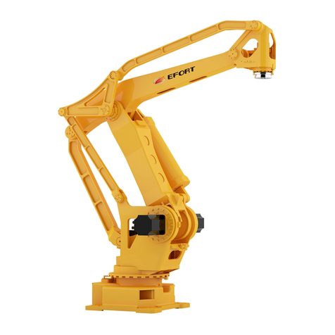
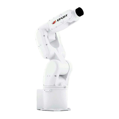
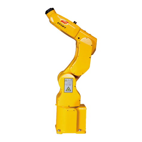
EFORT ER15-1400 User manual

ER15-1400 Electrical Operation and
Maintenance Manual for Industrial Robot
EFORT Intelligent Equipment Co., Ltd
Service Hotline(Tel):400-0528877

Electrical Operation and Maintenance Manual for ER15-1400 Industrial Robot
2
Statement
Thank you for purchasing EFORT Robot products. To ensure proper
set-up of products, please read this manual carefully before operation.
The content mentioned in this statement and manual involves your
personal and property safety. Not following the instructions and warnings
of the manual may cause injury to you and EFORT robots, as well as loss
of surrounding properties. This statement and manual are the latest
version until this batch of products leave the factory. Please visit the
official website, www.efort.com.cn to obtain up-to-date information in
the future.
This manual is only used as a normal operation guide. EFORT
company will not be liable for personal injury and property loss caused
by other reasons except product defects. Therefore, EFORT Company
solemnly advise people involved in robot operation, teaching,
maintenance, repair, equipment check, and other relevant activities
complete the training courses offered by EFORT, before being authorized
to do so.
Version:V 1.2

Electrical Operation and Maintenance Manual for ER15-1400 Industrial Robot
3
Content
Chapter One Safety............................................................................................................................. 1
1.1 Safety Instructions................................................................................................................ 1
1.2 Safety Criteria....................................................................................................................... 1
1.3 Safety Precautions during Work........................................................................................... 1
1.3.1 Safety in Robot Installation and Connection.............................................................3
1.3.2 Safety Before Starting Robot.....................................................................................4
1.3.3 Safety of Starting Robot............................................................................................ 5
1.3.4 Safety in Robot Test Run...........................................................................................6
1.3.5 Safety in Teaching......................................................................................................7
1.3.6 Safety in Automatic Operation.................................................................................. 8
1.3.7 Safety in Repair......................................................................................................... 9
1.3.8 Safety in Equipment Check and Maintenance........................................................ 10
Chapter Two Handling and Installation............................................................................................13
2.1 Overview.............................................................................................................................13
2.2 Basic Description................................................................................................................13
2.2.1 Unpacking List.........................................................................................................13
2.2.2 Preparation Before Installation................................................................................14
2.2.3 Storage Environment for Robot...............................................................................14
2.2.4 Operation Environment for Robot...........................................................................14
2.2.5 Start Robot in Cold Environment............................................................................15
2.2.6 Placement of Control Cabinet................................................................................. 15
2.3 Installation on Site.............................................................................................................. 17
2.3.1 Transporting Precautions......................................................................................... 17
2.3.2 Transporting of Control Cabinet..............................................................................17
2.4 Electrical Connection..........................................................................................................17
2.4.1 Robot Power............................................................................................................ 18
2.4.2 Robot power, signal and grounding cables..............................................................19
2.4.3 The IO cable of the robot body base....................................................................... 20
2.4.4 The IO cable of the arm of the robot body..............................................................22
2.4.5 External safety interface........................................................................................ 23s
Chapter Three Robot Control Cabinet System.................................................................................26
3.1 Composition of Robot Control Cabinet..............................................................................26
3.1.1 Basic Parameters......................................................................................................26
3.1.2 Electrical interface distribution............................................................................... 26
3.2 Motion Control Unit........................................................................................................... 27
3.4.1Motion Controller..................................................................................................... 27
3.2.2 Local IO definition and extension........................................................................... 32
3.2.3 Motion Control Card............................................................................................... 34
3.3 Servo Drive Unit.................................................................................................................35
3.4 Safety Function Unit...........................................................................................................39
3.4.1 Electrical Hardware................................................................................................. 40
3.4.2 Software...................................................................................................................40

Electrical Operation and Maintenance Manual for ER15-1400 Industrial Robot
4
3.5 Human Machine Interaction Unit.......................................................................................41
3.5.1 Button Operation Panel........................................................................................... 41
3.5.2 Main power switch.................................................................................................. 42
3.5.3 Emergency stop button............................................................................................ 42
3.5.4 Servo confirmation button.......................................................................................42
3.5.5 Hot swap button.......................................................................................................42
3.5.6 Teaching Pendant(Enable/Manual Press)...........................................................43
3.6 Power distribution management unit..................................................................................45
3.7 Brake Release Unit............................................................................................................. 46
3.7.1 Overview..................................................................................................................46
3.7.2 Location of Brake Release Unit.............................................................................. 46
3.7.3 Manual brake release using method and precautions..............................................47
3.8 Teaching Pendant Hot-Swap Unit...................................................................................... 48
3.8.1 Hot-unplug of Teach Pendant..................................................................................49
3.8.2 Hot-plug of teach pendant....................................................................................... 49
3.8.3 Common Problems.................................................................................................. 49
Chapter Four Maintenance................................................................................................................51
4.1 Introduction.........................................................................................................................51
4.2 Specific Safety Rules..........................................................................................................51
4.3 Maintenance Plans..............................................................................................................52
4.4 Check Activities..................................................................................................................53
4.4.1 Check the Sealing of Electric Cabinet.....................................................................53
4.4.2 Check the Wiring Harness....................................................................................... 53
4.4.3 Check the Working Condition of Main Electrical Components............................. 54
4.4.4 Check the Emergency Stop Switch......................................................................... 54
4.5 Change/Replacement Activities..........................................................................................55
4.5.1 Replace the Controller.............................................................................................55
4.5.2 Replace Safety Relay...............................................................................................56
4.5.3 Replace the Servo Power Drive...............................................................................57
4.5.4 Replace the Switching Power Supply..................................................................... 58
4.5.5 Replace the Fuses and Fuse Cores.......................................................................... 58
4.5.6 Replace the Fan........................................................................................................59
4.6 Replace the Battery.............................................................................................................60
4.7 Quick Recovery Method of Home Position....................................................................... 61
4.8 Cleaning.............................................................................................................................. 65
4.8.1 Overview..................................................................................................................65
4.8.2 Precautions...............................................................................................................65
Chapter Five Troubleshooting.......................................................................................................... 66
5.1 Overview.............................................................................................................................66
5.2 Common Hardware Faults..................................................................................................66
5.3 Controller Fault Handling...................................................................................................67
5.3.1 View Event Log....................................................................................................... 68
5.3.2 Fault Light Display on the Controller..................................................................... 69
5.3.3 Controller Fault Handling........................................................................................71
Electrical Operation and Maintenance Manual for ER15-1400 Industrial Robot
5
5.4 Drive Fault Handling.......................................................................................................... 71
5.5 Program Running Fault Handling...................................................................................... 72
Chapter Six Deactivation..................................................................................................................73
6.1 Overview.............................................................................................................................73
6.2 Environmental Information................................................................................................ 73
6.3 Discard the Robot............................................................................................................... 73
Chapter Seven Schematic Diagram.................................................................................................. 75
Appendix 1 Spare Parts List............................................................................................................. 76

Electrical Operation and Maintenance Manual for ER15-1400 Industrial Robot
1
Chapter One Safety
1.1 Safety Instructions
According to relevant national and local laws, regulations, and ordinances, safety instructions
are the most basic focus in operating industrial systems including robots.
The factory using robots are liable for personal injury and property damage led by the
operation of robot. Therefore, this manual and relevant materials together with regulations and
standards concerning health and safety must be understood and abided by.
For safety concerns, complying with the requirements in other manuals offered by EFORT is
also strongly advised. Safety information recorded in this manual is general and does not include
all the aspects of the operating system of robots. Therefore, necessary safety measures should be
taken and strictly abided by according to the real operation situations.
Operators must read the following information carefully and pay particular attention to the
safety measures listed in this chapter.
EFORT industrial robot users should ensure compliance with applicable safety laws and
regulations of the host country, and proper design and installation of necessary safety equipment
for robot system operators, whereas operators must familiarize themselves with the following
documents detailing operation and handling of industrial robots:
Operation Manual for EFORT Industrial Robot
Electrical Operation and Maintenance Manual for ER15-1400 Industrial Robot
Mechanical Operation and Maintenance Manual for ER15-1400 Industrial Robot
This manual covers all safe instructions in product manuals for robot and control cabinet.
Robot system should be designed and manufactured in an elaborate manner to achieve safe access
to areas for intervention during operation, adjustment, and maintenance. Safe and adequate access
to work position must be ensured for situations where it is necessary to operate in a safe and
protective space.
1.2 Safety Criteria
Prohibited Actions
1. Do not arbitrarily modify or dismantle the protective and safety devices of
industrial robot.
2. If waterlogging occurs, do not touch robot. Instead cut off all powers and drain the
site.
3. Industrial robots can only be operated by professionals who have received sufficient
training and guidance including those who have been familiar with this manual.
4. Ensure the surroundings of the emergency stop equipment is unblocked, and do not
pile up debris in front of it, which hinders operation in emergency situations.
5. Do not use inappropriate materials or make improper adjustments and
modifications.
6. Personnel who are unauthorized, or have not received training on operation and do

Electrical Operation and Maintenance Manual for ER15-1400 Industrial Robot
2
not understand the existing risks are not allowed to operate robot.
7. Do not use robots under the following circumstances:
• robot components exposed
• safety device disabled
• all or part of the fuse and/or mechanical equipment disabled
• requirements of processing materials not met
• No more than one person allowed to use the machine at one time
8. Strictly prohibit any actions mentioned above regarding violation of the use of
robot, especially the arbitrary use of non-original parts.
9. Do not move the protective device. Users are responsible for ensuring that the
protective device is fixed stably and operates in an orderly manner.
10. The safety device can only be moved during maintenance when operation
procedures are carried out by maintenance personnel and robot safety is ensured.
Mandatory Measures
1. Ensure nobody is within the danger area before starting robot.
2. All operators must receive training on operation and maintenance of industrial
robot.
3. The foreman shall continuously monitor the normal operation of all programs and
ensure the correct application of safety protective programs.
4. Maintenance is required to be performed in accordance with the maintenance
manual to keep the industrial robot clean and tidy.
5. Appropriate toolboxes should be prepared to store cleaning and maintenance tools.
Workers must wear personal protective equipment.
6. In addition to the above, testers must abide by current health and safety
regulations.
7. Stop the robot when it is malfunctioning, or is suspected of being damaged, not
running, or makes abnormal noises.
8. Once fire is discovered regardless of level, immediately call the police and
firefighters for rescue.
9. The door of the control cabinet must always be closed, and the key must be kept by
electrician.
10. Personnel are not allowed to enter the safety protective area when robot is
powered on.
11. Before turning on the automatic mode, all temporarily disabled safety functions
must be restored to normal working status.

Electrical Operation and Maintenance Manual for ER15-1400 Industrial Robot
3
Warning
1. The release of gravity and braking device may cause risks of falling.
2. The inspection of protective device may pose dangers to maintenance personnel
because they are not working. Therefore, maintenance personnel must be very careful
and take precautionary and protective measures.
1.3 Safety Precautions during Work
1.3.1 Safety in Robot Installation and Connection
Danger
Strictly follow the precautions below and refer to national/international standards
for all installations and connections. The design of safety functions should comply with
Robot Safety Requirements (GB11291.1-2011/ISO10218-1:2006).
1.Please read and understand all manuals, specifications, and other relevant
documents provided by EFORT before operation. In addition, completely understand
procedures of operation, teaching, and maintenance. Meanwhile, make sure all safety
measures are effective in place.
2. Avoid exceeding the specified height during robot transportation:
• Only allow qualified personnel to operate forklifts and cranes, and to move/transport
robot body, control cabinet, etc.
• Never approach or walk under the lifted robot body or control cabinet during
transportation.
• Never stay on the robot body or control cabinet during transportation, or touch and
support them manually.
3. Hook the wire rope to the ring according to the robot lifting figure, and confirm the
ring is not loose before operation.
4. Please remove teach pendant and its bracket to prevent cables from hooking other
equipment when transferring the control cabinet with sling.
5. Please remove all unnecessary objects and clear the passage to the installation
location before transporting robot.
6. Please fasten the control cabinet to prevent tipping over if it is transported by a
forklift.
7. Please protect robot from collisions and impacts because it is composed of
sophisticated components.
8. Never connect to the power cable of the control cabinet when the main power of the
installation site is on, or it may cause extreme dangers and even electric shock. Make
sure the main power is switched off when the input power cable is being connected. In

Electrical Operation and Maintenance Manual for ER15-1400 Industrial Robot
4
order to prevent the input power supply or circuit breaker from being turned on
mistakenly, please place a shut-down tag on all power supply units and circuit breakers
to indicate they are in check/maintenance/repair. Meanwhile, lock or place a truck to
clamp the main power switch.
9. Be sure to close the input power connection end with plate when the wiring is
completed. Otherwise, it poses extreme dangers and may cause electric shock accidents
if the end is touched mistakenly.
10. Please place the motor/signal cable connected to the robot in the cable trough to
prevent damage. Please also take measures to prevent them from being compressed.
Do not connect to the power supply until all the connections between the control
cabinet and the robot body are completed. Otherwise, it may pose dangers and cause
accidents such as electric shock.
1.3.2 Safety Before Starting Robot
Danger
Strictly follow the precautions below and refer to national/international standards
before starting robot. The design of safety functions should comply with Robot Safety
Requirements (GB11291.1-2011/ISO10218-1:2006).
1.Please read and understand all manuals, specifications, and other relevant
documents provided by EFORT before operation. In addition, completely understand
procedures of operation, teaching, and maintenance. Meanwhile, make sure all safety
measures are effective in place.
2. Make sure install control cabinet, operation panel, and other control devices outside
the protective equipment (fence) to monitor the robot’s overall motion range. The
recommended height of the control cabinet is 1m.
3. Confirm no obstacles, such as humans, packaging materials, clamps are within the
motion range of the robot arm.
4. Eliminate any areas where people may be trapped between fixed equipment and
mobile equipment.
5. Please confirm whether the voltage, frequency, and cable specifications of the power
supply meet the requirements before the power cables are being connected.
6. Ensure the control cabinet and peripheral equipment are properly grounded. The
ground wires of each cannot be connected but grounded separately. Please install
power filter or equivalent device on the power inlet of the adjacent robot control
cabinet if electromagnetic switches, contactors, and other devices are added to
peripheral equipment.
7. Before switching on the power of the robot, please confirm installation meets the
requirements.
8. A supervisor who should have completed relevant training offered by EFORT must

Electrical Operation and Maintenance Manual for ER15-1400 Industrial Robot
5
be assigned for operation monitor.
9. The system must be equipped with monitor instruments to automatically detect
abnormalities in water and gas supply in time for application items (water, compressed
air, protective gas, etc.).
10. If large amounts of scraps, metal dust particles, and tiny particles are generated
during work, please blanket robot body, control cabinet and peripheral devices with
proper covers.
11. Robots are allowed to be used at altitudes below 1000 meters. If the altitude exceeds
1000 meters, please contact EFORT sales staff.
12. When the robot operates in an environment containing radiation (such as
microwave, ultraviolet, laser, X-ray), effective protective measures should be taken,
such as adding protective cover or other ways, to avoid the robot misoperation or
accelerated insulation aging phenomenon.
1.3.3 Safety of Starting Robot
Danger
To start robot, first connect the power cable, then turn the power switch from OFF to
ON. Strictly follow the precautions below and refer to national/international standards
to operate the procedures.
The design of safety functions should comply with Robot Safety Requirements
(GB11291.1-2011/ISO10218-1:2006).
Before starting robot, please confirm the emergency stop switch works properly.
1.Please read and understand all manuals, specifications, and other relevant
documents provided by EFORT before operation. In addition, completely understand
procedures of operation, teaching, and maintenance. Meanwhile, make sure all safety
measures are effective in place.
2. Check the names and functions of all switches, displays and signals needed for robot
operation.
3. Do not enter the safety fence unless the power supply is disconnected. Meanwhile,
confirm the protective devices function properly before starting the robot.
4. If several operators work together in the robot operation system, make sure all of
them and relevant personnel are aware that robot should be activated before start.
5. Before switching on the motor, starting teaching, or automatic operation, please
reconfirm no humans or left obstacles are within the safety fence or around the robot.
6. When starting the robot and resuming operation from a faulty state, please put your
hand on the emergency stop switch after turning on the power of the control cabinet to
immediately cut off the power of the motor in case of abnormalities.

Electrical Operation and Maintenance Manual for ER15-1400 Industrial Robot
6
7. Before activating robot, please reconfirm the following conditions are met.
• Operators on site shall confirm the environment and be trained.
• The installation is correct and stable.
• All the connections in the control cabinet are correct. The power supply specifications
(power supply voltage, frequency, etc.) meet the requirements.
• All the application connections (water, compressed air, protective gas, etc.) are correct
and consistent with the specifications and models.
• The connections to peripheral devices are correct.
• In addition to the installation of software to limit motion, mechanical stop or switch
are also installed to limit robot's motion range.
• If robot is ceased by mechanical limit stop, please make sure the relevant parts are
checked or the invalid mechanical limit stop is replaced (if necessary).
• Safety measures are taken: protective devices, such as safety fences or alarm devices
and interlocking signals, are installed.
• Protective devices and interlock function properly, operators are required to receive
safety training and hold work license.
• Environmental conditions (temperature, humidity, light, noise, dust, etc.) meet the
requirements. In other words, they do not exceed the specifications set for the system
and the robot.
1.3.4 Safety in Robot Test Run
Danger
Errors concerning design, teaching, and working may exist in teaching program,
clamps, logic controllers, and other parts in robot test run. Therefore, safety awareness
must be further enhanced during test runs.
The following procedures need to be paid attention to during the test run:
1. Confirm whether the buttons, switches, and signals to stop the robot, such as the
emergency stop button and hold/run switch, operate properly. Accidents cannot be
prevented if robot cannot be stopped in case of dangerous situations.
2. Set the operating speed to low speed (about 5% to 10%) and confirm the teaching
action during robot test run. Check the operation repeatedly in 2 to 3 cycles. If
problems are detected, stop the robot immediately and make adjustment. Gradually
increase the speed (50%→70%→100%) after no problems are found. Then repeat the
action in 2 to 3 cycles each.

Electrical Operation and Maintenance Manual for ER15-1400 Industrial Robot
7
1.3.5 Safety in Teaching
Danger
EFORT advises teaching should be administered outside the safety fence. However, if
it is necessary to enter it, strictly follow the precautions below and refer to
national/international standards.
The design of safety functions should comply with Robot Safety Requirements
(GB11291.1-2011/ISO10218-1:2006).
Please confirm the emergency stop switch functions properly before teaching.
Operators shall be trained before taking up their posts.
1.Please read and understand all manuals, specifications, and other relevant
documents provided by EFORT before operation. In addition, completely understand
procedures of operation, teaching, and maintenance. Meanwhile, make sure all safety
measures are effective in place.
2. Please confirm all protective devices (safety fences) work properly before starting
the robot.
3. Teaching should be administered by one operator and one supervisor, who bears
the responsibility of safety supervision. Confirm signals, such as "start work", before
teaching.
4. Before entering the safety fence, the operator must turn the teaching switch on the
teach pendant to manual to prevent accidental switch of the control cabinet to
automatic mode. Once the robot makes any abnormal movement, the emergency stop
switch must be immediately pressed and robot exits the work area from the preset
evacuation route.
5. Please install an emergency stop switch which enables the supervisor to monitor
the overall robot movement outside the fence. Once the robot makes incorrect
movement, the supervisor must be able to press the switch very conveniently to stop
the robot immediately. In addition, if you need to restart the robot after an
emergency stop, please reset and restart the manual operation outside the safety
fence. The operator and the supervisor must be specially trained and qualified
personnel.
6. Please clearly mark teaching is in progress to prevent other people from making
wrong operations on the control cabinet, operation panel, teaching pendant, or any
robot system devices.
7. Before confirming the trajectory and teaching data, please clear all the personnel
and obstacles left within the safety fence and around the robot. The confirmation
work should be done outside the safety fence. The speed of the robot should be equal
to or less than safety speed (250mm/s) until being confirmed normal.
8. If robot needs to be restarted after an emergency stop, please reset and restart
manually outside the safety fence. At the same time, confirm all safety conditions are

Electrical Operation and Maintenance Manual for ER15-1400 Industrial Robot
8
met and no humans or obstacles left are around the robot or within the safety fence.
9. During teaching, please confirm the motion range of the robot. Approaching the
underside of the robot is prohibited and may pose risks causing accidents. It’s also
worth noticing that it is forbidden to approach the robot arms to prevent risks of
workpiece falling when robot’s claws grip workpieces.
10. For safety concern, the maximum speed of the robot is limited to 250mm/s (safe
operating speed) in teaching or inspection mode. However, after teaching is
completed or robot is recovered from errors, the operator should set the speed as low
as possible in verifying teaching data.
11. In the teaching process, both the operator and the supervisor should continuously
monitor the robot for abnormal movements, possible collisions and squeezing points
on and around the robot. Meanwhile, please confirm the safe passage for the operator
is clear in case of emergency evacuation.
12. Please set the robot's software limit beyond the robot’s motion range after
teaching is completed. Refer to the EFORT Industrial Robot Operation Manual for
the setting.
1.3.6 Safety in Automatic Operation
Danger
Because teaching program repeats fast, please strictly follow the precautions below
and refer to national/international standards.
The design of safety functions should comply with Robot Safety Requirements
(GB11291.1-2011/ISO10218-1:2006).
Please confirm all switches function properly before repair.
1.Please read and understand all manuals, specifications, and other relevant
documents provided by EFORT before operation. In addition, completely understand
procedures of operation, teaching, and maintenance. Meanwhile, make sure all safety
measures are effective in place.
2. In automatic operation, any part of the body should never enter the safety fence.
Please confirm no humans or obstacles left are within the safety fence before starting
operation.
3. In automatic operation, the robot may seem to stop while waiting for the delay of
the timer or external signal input. However, do not approach it at this time because it
immediately resumes operation when the two conditions mentioned above are met.
4. In automatic operation, this situation will be extremely dangerous: if the gripping
force of the workpiece is not enough, the workpiece may be thrown off during the
movement of the robot. Be sure to confirm that the workpiece has been firmly
grasped. When the workpiece is grasped by a pneumatic gripper, an electromagnetic

Electrical Operation and Maintenance Manual for ER15-1400 Industrial Robot
9
mechanism, etc., please use a fail-safe system to ensure that the workpiece will not be
ejected once the driving force of the mechanism is suddenly disconnected. Even in the
event of an error, when the possibility of the workpiece coming out is minimal, please
install a safety fence, such as a net cover.
5. Tag Automatic Operation on the safety fence and do not enter the work area. Please
also confirm the safety passage for operators is clear in case of emergency evacuation.
6. If the robot stops due to a fault during automatic operation, please check the
displayed fault information and follow the correct recovery steps to recover and
restart the robot.
7. After recovery, please confirm all safe working conditions are met and no humans,
clamps, peripheral devices, or obstacles left are within the safety fence or around the
robot before restarting it.
1.3.7 Safety in Repair
Danger
For repair, please strictly follow the precautions below and refer to relevant
national/international standards.
The design of safety functions should comply with Robot Safety Requirements
(GB11291.1-2011/ISO10218-1:2006).
Please confirm all switches function properly before repair.
1.Please read and understand all manuals, specifications, and other relevant
documents provided by EFORT before operation. In addition, completely understand
procedures of operation, teaching, and maintenance. Meanwhile, make sure all safety
measures are effective in place.
2. Please confirm all necessary safety measures are ready and function properly
before entering the safety fence.
3. Please switch off the control power supply to the main power supply before
entering the safety fence. Meanwhile, place a clear sign displaying shutdown and
repair in progress and lock or clamp the main power switch to prevent mistakenly
turning on power.
4. Only qualified personnel who have received special training on corresponding
robot series can perform repair.
5. Enough space around the robot should be guaranteed to prevent interference from
peripheral devices which should be fastened in case of any sudden movement.
6. Please be sure to switch off the automatic operation before entering the safety
fence. If robot moves abnormally, immediately press the emergency stop switch and
evacuate from the preset route.
7. Please install an emergency stop switch which enables the supervisor to monitor the

Electrical Operation and Maintenance Manual for ER15-1400 Industrial Robot
10
overall robot movement outside the fence. Once the robot makes incorrect movement
in repair, the supervisor must be able to press the switch very conveniently to stop the
robot immediately. In addition, if you need to restart the robot after an emergency
stop, please reset and restart the manual operation outside the safety fence. The
operator and the supervisor must be specially trained and qualified personnel.
8. Both the operator and the supervisor must continuously pay close attention to any
abnormal movements, possible collisions, and the surroundings of the robot.
9. Only use parts provided by EFORT for replacement.
10. Please support the robot arm with proper lifting device before removing any servo
motor of joint axis. The removal causes fail of the brake mechanism of the axis.
Without reliable support, the arm falls. Please be aware same dangers occur if you
press any axis brake release switch on the control cabinet.
11. Turn off the control power supply and wait at least seven minutes for replacement
of the drive module and power supply module. Then start the replacement and
remove connectors after confirming the output voltage of the power supply is 0V.
Please be aware do not touch any part to prevent electric shock or burns.
12. If compressed air or water is supplied, please cut off the supply source and release
the remaining pressure in pipelines before repair.
13. Make sure the emergency stop signal of the auxiliary axis and the emergency stop
circuit of the control cabinet are concatenated when auxiliary axes are added.
14. When changing robot parts, be sure to confirm whether the replaced parts match
the original parts, and carefully check the schematic diagram to prevent the wrong
wiring. Otherwise, the components of the robot control cabinet and external
components may be damaged.
1.3.8 Safety in Equipment Check and Maintenance
Danger
Please strictly follow the precautions below and refer to relevant national/international
standards for robot clean, check, maintenance, and replacement of parts to prevent
system faults.
Make sure all the emergency stop switches function properly before check and
maintenance.
1.Please read and understand all manuals, specifications, and other relevant
documents provided by EFORT before operation. In addition, completely understand
procedures of operation, teaching, and maintenance. Meanwhile, make sure all safety
measures are effective in place.
2. Please remove unnecessary object and clear passage to the installation position
before check and maintenance.

Electrical Operation and Maintenance Manual for ER15-1400 Industrial Robot
11
3. Only qualified personnel who have completed special training on this specific robot
or robots in the same series can perform check and maintenance.
4. Enough space around the robot should be guaranteed to prevent interference from
peripheral devices which should be fastened in case of any sudden movement.
5. Please cut off the power supply of the entire line or the power of the robot. Also cut
off the power supply up to the main power supply as needed before entering the safety
fence. Place a clear sign displaying shutdown, check or repair in progress and lock or
clamp the main power supply switch to prevent the power being turned on mistakenly.
If cutting off the entire line fails, please install temporary safety fence between the
target robot and neighbouring robots.
6. Please correctly switch off all the power of signal related equipment to ensure safety
during check and maintenance on interlocking signal chain. Do not enter the safety
fence during work.
7. Please install an emergency stop switch which enables the supervisor to monitor the
overall robot movement outside the fence. Once the robot makes incorrect movement
in repair, the supervisor must be able to press the switch very conveniently to stop the
robot immediately. In addition, if you need to restart the robot after an emergency
stop, please reset and restart the manual operation outside the safety fence. The
operator and the supervisor must be specially trained and qualified personnel.
8. Before entering the safety fence, the operator must turn the teaching switch on the
teach pendant to manual to prevent accidental switch-on of the control cabinet to
automatic mode. Once the robot makes any abnormal movement, the emergency stop
switch must be immediately pressed and robot exits the work area from the preset
evacuation route.
9. Both the operator and the supervisor must continuously monitor the robot for any
abnormal movement, collisions, or squeezing during check and maintenance.
Meanwhile, please confirm the safety passage for the operator is clear for evacuation.
10. If it is necessary to remove the safety fence during check and maintenance, please
take adequate safety measures:
• Place the robot and peripheral devices properly.
• Lock/calibrate the power and switch to avoid the power being turned on or the
switch being turned to automatic mode mistakenly.
• Reinstall the safety fence and confirm all safety measures, functions remain the
same when check and maintenance are completed.
11. Only use parts supplied by EFORT for replacement. Be sure to use teaching mode
and move the robot as slow as possible in check and maintenance.
12. Turn off the control power supply and wait at least seven minutes for replacement
of the drive module and power supply module. Then start the replacement and remove
connectors after confirming the output voltage of the power supply is 0V. The heat sink
or regenerative generator may main hot right after the stop of the movement.

Electrical Operation and Maintenance Manual for ER15-1400 Industrial Robot
12
Therefore, please be cautious do not touch any hot part.
13. Please support the robot arm with proper lifting device before removing any servo
motor of joint axis. The removal causes fail of the brake mechanism of the axis.
Without reliable support, the arm falls. Please be aware same dangers occur if you
press any axis brake release switch on the control cabinet.
14. The robot must remain the same posture before and after the maintenance. Please
record posture data before the replacement of parts.
15. Check and record the location, connector number, installation method, and set data
of the printed circuit board or cable at the beginning of the replacement process, so
they can be recovered properly. The locking mechanism of the connector must be
locked tightly after it is inserted. Never touch the pins of the connector.
16. If compressed air or water is supplied, please cut off the supply source and release
the remaining pressure in pipelines before repair.
17. Please confirm all the protective devices function properly after check and
maintenance.
18. EFFORT will not be liable for any change or modification without authorization.
19. Numerous back-up batteries are built in the robot arm and control cabinet. Misuse
will cause burn, overheat, explosion, eruption, leak, etc. Therefore, the following
protocols must be strictly followed.
• Only use batteries specified by EFORT;
• Do not recharge, dismantle, change, or heat batteries;
• Do not throw batteries in water or fire;
• Never use surface-damaged batteries the inside of which may be short circuited.
• Do not use metals, such as wires, to short-circuit the positive and negative
terminals of the battery. Do not discard used batteries in ground garbage that will be
incinerated, landfilled, or dumped. Please pack them in a bag for disposal to prevent
them from being in contact with other metals. Please also handle them properly in
accordance with local regulations.
20. Make sure the emergency stop signal of the auxiliary axis and the emergency stop
circuit of the control cabinet are concatenated when auxiliary axes are added. Then
test the safety functions of the emergency stop circuit to ensure safety control logic.
21. When changing robot parts, be sure to confirm whether the replaced parts match
the original parts, and carefully check the schematic diagram to prevent the wrong
wiring. Otherwise, the components of the robot control cabinet and external
components may be damaged.

Electrical Operation and Maintenance Manual for ER15-1400 Industrial Robot
13
Chapter Two Handling and Installation
2.1 Overview
This chapter includes installation instructions and information about ER15-1400 robot in
workplace.
It is vitally important to read all the safety information before any installation. Please be sure
to read the following information carefully: EFORT robot safety manual, general safety
information in the first chapter of this manual that must be read thoroughly, and introduction of
dangers and safety risks during operation.
2.2 Basic Description
2.2.1 Unpacking List
1、Before unpacking, please confirm whether the outer packaging of the product is intact;
2、After unpacking, please confirm whether all parts of the robot are complete and whether
the model is consistent with the order. If you find missing or wrong parts, please contact the
supplier in time.
Table 2-1 Robot Unpacking List
Robot Unpacking List
Number
Name
Standard configuration
Number
Unit
Remarks
1
Robot body
Standard configuration
1
SET
2
Robot control cabinet
Standard configuration
1
SET
3
Control cabinet – robot
body connecting cables
Power cable
1
SET
Standard length 8m, cable
optional length 16m
4
Encoder cable
1
SET
Standard length 8m, cable
optional length 16m
5
Ground wire
1
PC
Standard length 8m, cable
optional length 16m
6
Robot teaching pendant
and cables
Standard configuration
1
SET
7
Operation instruction
Standard configuration
1
SET
8
Final factory inspection
report
Company standard
1
PC
9
Product certification
Company standard
1
PC
10
Robot accessories
Accessory box
1
PC
11
Main power cable of
robot
Standard configuration
1
SET
Has been put in the
accessory box
12
Other
One 10A glass tube fuse
Note: The above is a standard configuration list, excluding customized models. For details,

Electrical Operation and Maintenance Manual for ER15-1400 Industrial Robot
14
please refer to the accompanying Robot Unpacking List.
2.2.2 Preparation Before Installation
This section includes information required for unpackaging, initial installation, and
reinstallation of the robot.
The following steps need to be checked before installation:
Table 2-2 Installation Precautions
1
Inspect the robot visually for any damage.
2
Make sure the lifting device for transporting the robot fits its weight.
3
If the robot is not installed immediately, it must be stored according to the
storage requirements.
4
Ensure the expected operation environment is in accordance with requirements.
5
Before transporting the robot to the installation site, be sure the ground is
suitable for installation.
6
Please check the stability of the robot before moving it.
7
After the above conditions are met, move the robot to site and install it
according to instructions below.
2.2.3 Storage Environment for Robot
The following table shows storage requirements for robot:
Table 2-3 Storage Environment
Parameter
Value
minimum environment temperature
-40℃
maximum environment temperature
+55℃
maximum environment humidity
93%RH, no condensation(40℃)
2.2.4 Operation Environment for Robot
The following table shows operation requirements for robot:
Table 2-4 Operation Environment
Parameter
Value
minimum environment temperature
-10°C
maximum environment temperature
+45°C
maximum environment humidity
80%RH, no condensation(40℃)

Electrical Operation and Maintenance Manual for ER15-1400 Industrial Robot
15
2.2.5 Start Robot in Cold Environment
The operation procedures describe how to start robot in a cold environment. The heating rate
must be adjusted according to the temperature and the program used. The table below
demonstrates speed adjustment method:
Table 2-5 Work Cycle of Starting Robot in Cold Environment
Work Cycle
Speed Rate
3 cycles
20
5 cycles
50
5 cycles
80
5 cycles
100
2.2.6 Placement of Control Cabinet
Dimensions of ER15-1400 Robot control cabinet (size in mm).
Fig. 2-1 Dimension of Control Cabinet
Please do not block the vents of the control cabinet during placement so as not to affect
dissipation. Please reserve a space of more than 150mm around the cabinet.
(Can be connected to the 19-inch rack using 4-M6×10 self-tapping
Other manuals for ER15-1400
2
Table of contents
Other EFORT Robotics manuals

EFORT
EFORT ER10-3-900 User manual

EFORT
EFORT ER12-4-2000 User manual

EFORT
EFORT EC2-M User manual

EFORT
EFORT ER3-600 User manual

EFORT
EFORT ER10-1600 User manual

EFORT
EFORT ER20-1700 User manual

EFORT
EFORT ER10-1600 User manual

EFORT
EFORT ECR5 Instruction manual

EFORT
EFORT ER6-2000 User manual

EFORT
EFORT ER20-1700 User manual

EFORT
EFORT ER6-1400 User manual

EFORT
EFORT ER15-4-1600 User manual

EFORT
EFORT ER3-600 User manual

EFORT
EFORT ER15-4-1600 User manual

EFORT
EFORT ER7-700 User manual

EFORT
EFORT ER210-2700 User manual

EFORT
EFORT ER130-4-2800 User manual

EFORT
EFORT ER15-1400 User manual

EFORT
EFORT ER20-1100 User manual

EFORT
EFORT ECR5 User manual