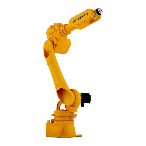
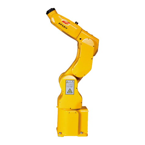
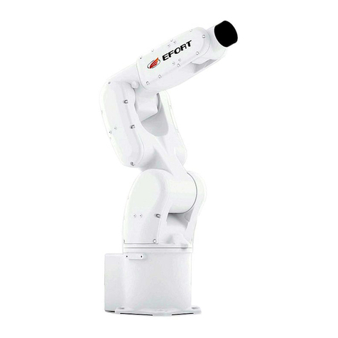
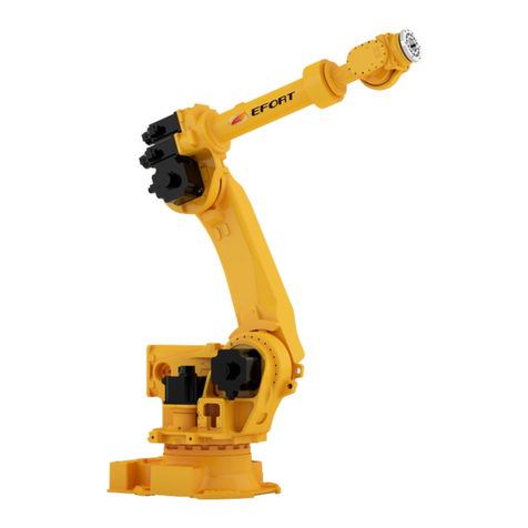
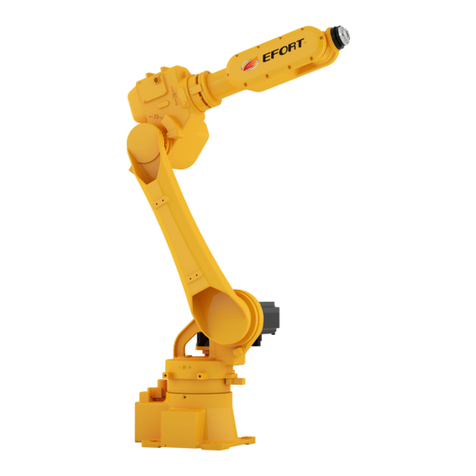
EFORT ER3-600 User manual

ER3-600 Mechanical Operation and
Maintenance Manual for Industrial Robot
EFORT INTELLIGENT EQUIPMENT CO.,LTD
Hotline(Tel):400-0528877


Mechanical Operation and Maintenance Manual for Industrial Robot ER3-600
Statement
Thank you for purchasing EFORT robot products. In order to ensure
that the ER3-600 products have been set correctly, please read this
operation manual carefully before using.The contents mentioned in this
announcement and the manual are related to your personal and property
safety. If you do not follow the instructions and warnings in the manual or
operate without authorization, it may cause personal injury to you and the
people around you or property damage to the robot or other objects around
you. This announcement and manual are the latest version of this batch of
products before delivery. Please visit www.efort.com.cn for updated
information.
This manual is only used as a guide for the normal operation of the
product. During the use of the product, EFT will not be liable for personal
injury and property loss caused by other reasons except product defects.
Our company seriously suggests that: the personnel who participate in
robot operation, teaching, maintenance, repair, spot inspection and other
related activities should not be given permission to operate the robot
before completing the training courses prepared by company.
Version: V 1.1


Mechanical Operation and Maintenance Manual for Industrial Robot ER3-600
I
Content
Chapter One: Safety........................................................................................................................................... 1
1.1 Instruction for Safe Use of Robots.......................................................................................................... 1
1.1.1 Safety Precautions during Adjustment,Operation,Mainteance........................................................ 1
1.1.2 Safety Countermeasures of Robot Body.......................................................................................... 3
1.2 Shift,Transfer, and Sale of Robots........................................................................................................... 7
1.3 Abandonment of Robots.......................................................................................................................... 7
Chapter Two: Basic Description........................................................................................................................ 9
2.1 Robot System Composition..................................................................................................................... 9
2.2 Unpacking Check.....................................................................................................................................9
2.3 Machine Body Nameplate..................................................................................................................... 10
2.4 Body Part Composition and Identification of Each Axis...................................................................... 10
2.5 Robot Axis Range Limit and Home Position........................................................................................ 11
2.6 Robot Performance Parameters............................................................................................................. 12
2.7 Allowable Value of Wirst Payload......................................................................................................... 15
2.7.1 Allowable Weight............................................................................................................................15
2.7.2 Allowable Maximum of Static Payload Torque............................................................................. 15
2.7.3 Allowable Maximum of Moment of Inertia................................................................................... 15
2.7.4 Allowable Payload Curve Diagram................................................................................................ 15
Chapter Three: Handling and Installation........................................................................................................16
3.1 Robot Handling......................................................................................................................................17
3.1.1 Handling Precautions......................................................................................................................17
3.1.2 Handling Method............................................................................................................................ 17
3.2 Robot Installation...................................................................................................................................18
3.2.1 Setting of Safety Fence................................................................................................................... 19
3.2.2 Robot Installation Method.............................................................................................................. 19
3.2.3 Ground Mounting........................................................................................................................... 20
EFORT INTELLIGENT EQUIPMENT CO.,LTD
II
3.2.4 Suspended Installation.................................................................................................................... 20
3.3 Installation Site and Environment......................................................................................................... 21
3.4 Intergrated Application Installation Interface........................................................................................21
Chapter Four: Overhaul and Maintenance .....................................................................................................23
4.1 Preventive Maintenance.........................................................................................................................25
4.1.1 Daily Inspection..............................................................................................................................25
4.1.2 Quarterly Inspection....................................................................................................................... 25
4.1.3 Annual Inspection........................................................................................................................... 26
4.1.4 Inspect Every Two Years.................................................................................................................26
4.2 Overhaul of Main Bolts......................................................................................................................... 26
4.3 Conveyor Belt Maintenance.................................................................................................................. 27
4.4 Robot Maintenance and Use Area......................................................................................................... 30
4.5 Home Position Calibration.....................................................................................................................31
4.5.1 Home Position Calibration Method................................................................................................31
4.5.2 Mechanical Home Position Calibration of Each Axis....................................................................31
4.6 Battery Replacement..............................................................................................................................32
Appendix.......................................................................................................................................................... 32
A Screw Tightening Torque Table............................................................................................................... 34
B Backup List...............................................................................................................................................34

Mechanical Operation and Maintenance Manual for Industrial Robot ER3-600
1
Chapter One: Safety
1.1 Instructions for Safe Use of Robots
Before performing installation, operation, maintenance, and overhaul operations, please be sure to
read this manual and other attached documents thoroughly and use this product correctly. Please fully grasp
the equipment knowledge, safety information and all precautions before using this product. This manual
uses the following symbols to indicate their importance.
Danger
Danger!
It means that if the handling is wrong, it will cause the user's death or serious injury, and
the situation is very dangerous.
Warning
Warning!
It indicates a situation that will cause death or serious injury to the user if the handling is
incorrect.
Attention
Attention!
It indicates a situation that will cause minor injuries or property damage to the user if the
handling is incorrect.
1.1.1 Safety Precautions during Adjustment, Operation, Maintenance, etc.
1)Operators must wear work clothes, safety helmets, safety shoes, etc.
2)When turning on the power, make sure that there are no workers within the robot's operating range.
3)The power must be cut off before entering the robot's range of motion for work.
4)When overhaul, maintenance and other operations must be carried out under the power-on state, two
persons should work in a team at this time. One person maintains a posture that can immediately press
the emergency stop button, while the other person is within the robot's range of motion, staying
vigilant and working quickly. In addition, you should confirm the retreat path before proceeding.
5)The load on the wrist and the robot arm must be controlled within the allowable carrying weight and
torque. If the allowable carrying weight and torque regulations are not observed, it will lead to
abnormal action or premature damage of mechanical components.
6)It is forbidden to disassemble and work on parts not covered in the maintenance manual.
The robot is equipped with various self-diagnostic functions and abnormality detection functions, so
that it can stop safely even if an abnormality occurs. Even so, accidents caused by robots still occur

EFORT INTELLIGENT EQUIPMENT CO.,LTD
2
from time to time.
Danger
Danger! Most robot accidents are as follows:
1、The automatic operation was performed without confirming whether there is
anyone in the robot's motion range.
2、It enters the robot's motion range in the automatic operation state, and the robot
starts suddenly during the operation.
3、You just notice the robot in front of you, ignoring the others.
The above-mentioned accidents were all caused by the same reasons as "ignorance of safety operation
procedures" and "no idea that the robot would move suddenly". In other words, they are all accidents
caused by man-made unsafe behaviors such as "temporary negligence" and "failure to follow the prescribed
steps."
"Emergency situations" make it too late for operators to implement "emergency stop", "flee" and other
behaviors to avoid the accident, which may lead to major accidents. "Emergency situations" generally have
the following types.
1)Low-speed action suddenly becomes high-speed action.
2)Other operators performed the operation.
3)A different program was started due to an abnormality or program error in the peripheral equipment.
4)Abnormal operation due to noise, malfunction, defect, etc.
5)Misoperation.
6)Originally planned to regenerate at low speed to perform the action, but it performed the high-speed
action.
7)The work pieces transported by the robot fall and scatter.
8)When the work piece is in the stopped state of clamping and interlocking standby, it suddenly loses
control.
9)The next or behind robot performed the action.
The above are only some examples, and there are many forms of "emergency situations". In most
cases, it is impossible to "stop" or "escape" a robot that moves suddenly, so the following best
countermeasures should be implemented to avoid such accidents.
Danger
Be careful and approach the robot cautiously.
Danger
When the robot is not in use, measures such as "press the emergency stop button"
and "cut off the power" should be taken to prevent the robot from moving.

Mechanical Operation and Maintenance Manual for Industrial Robot ER3-600
3
Danger
During the operation of the robot, please configure a monitor (the third party) who
can immediately press the emergency stop button to monitor the safety status.
Danger
During the operation of the robot, the operation should be carried out in a state
where the emergency stop button can be pressed immediately.
In order to comply with these principles, it is necessary to fully understand the following precautions
and follow them.
1.1.2 Safety Countermeasures of Robot Body
Attention
The design of the robot should remove unnecessary protrusions or sharp parts, use
materials that adapt to the working environment, and adopt a fail-safe protection
structure that is not prone to damage or accidents during operation. In addition, it
should be equipped with misoperation detection stop function and emergency stop
function when the robot is in use, as well as interlocking function to prevent the
danger of the robot when the peripheral equipment is abnormal, so as to ensure
safe operation.
Warning
The main body of the robot is a multi-joint manipulator structure, and the angle of
each joint in the movement is constantly changing.
When you must approach the robot for teaching and other tasks, be careful not to
get caught by the joints. Each joint action end is equipped with a mechanical stop,
which has a high risk of being clamped, so special attention should be paid to it.
In addition, if the servo motor is removed or the brake is released, the robot arm
may fall due to its own weight or move in an uncertain direction. Therefore,
measures to prevent falling must be implemented, and the surrounding safety
conditions must be confirmed before operation.
Attention
When installing the attached machine on the end effector and the mechanical arm,
the size and quantity of screws specified in this book should be strictly observed,
and the torque wrench should be used to tighten according to the specified torque.
In addition, do not use rusty or dirty screws.
Unspecified tightening and imperfect methods will loosen the screws and cause
major accidents.

EFORT INTELLIGENT EQUIPMENT CO.,LTD
4
Attention
When designing and manufacturing the end effector, it is controlled within the
allowable payload range of the robot wrist.
Attention
The fail-safe protection structure should be adopted, even if the power supply or
compressed air supply of the end effector is cut off, the installation object will not
be released or fly out, and the corner or protruding part should be treated to
prevent damage to people and objects.
Attention
The fail-safe protection structure should be adopted, even if the power supply or
compressed air supply of the end effector is cut off, the installation object will not
be released or fly out, and the corner or protruding part should be treated to
prevent damage to people and objects.
Attention
It is strictly forbidden to supply power, compressed air, and welding cooling water
outside the specifications, which will affect the performance of the robot and cause
abnormal operations, malfunctions, damage and other dangerous situations.
Attention
Although electromagnetic interference is related to its type or intensity, there is no
perfect countermeasure with current technology.
When the robot is in operation or when the power is on, the operation precautions
and regulations should be followed. Due to electromagnetic waves, other noises, and
substrate defects, the recorded data will be lost.
Therefore, please back up programs or frequently used data to an external storage
medium such as a Compact flash card.
Attention
In a large-scale system, multiple operators are involved in the work. When it is
necessary to talk at a distance, the intention should be correctly conveyed by means
of gestures, etc.
Factors such as noise in the environment can make it impossible to convey the
meaning correctly and cause accidents.

Mechanical Operation and Maintenance Manual for Industrial Robot ER3-600
5
Attention
Industrial robot gesture method (example)
1. Connect: Do the work
related to the connection
2. No way! Disconnect:
Raise your right hand and
wave vigorously left and
right
3. Is that OK? (to
confirm):Raise your right
hand up high forward
4. OK: Raise your right
hand up high forward
Use your thumb and index
finger to form a circle
5. Wait a moment: The
right hand is facing the
opponent
Straight up arms
horizontally
6. Leave: Stretch your
right arm horizontally
and weave to the left
Attention
Operators should also maintain awareness of escape at all times during operations.
It must be ensured that in an emergency, you can escape immediately.
Attention
Always pay attention to the actions of the robot, and do not work with your back to
the robot.
Slow response to robot movements can also lead to accidents.

EFORT INTELLIGENT EQUIPMENT CO.,LTD
6
Attention
When an abnormality is found, the emergency stop button should be pressed
immediately.
This requirement must be thoroughly implemented.
Attention
According to the setting place and operating content, the relevant operation
regulations and checklists such as starting method, operation method, solution in
case of abnormality, etc. of the robot should be compiled. And carry out the
operation according to the operating regulations. Operation only based on the
memory and knowledge of the operator can cause accidents due to forgetting and
mistakes.
Attention
For the completed program, use the storage protection function to prevent
accidental editing.
Attention
When teaching, confirm the program number or step number before proceeding.
Editing procedures and steps incorrectly can cause accidents.
Attention
When it is not necessary to make the robot move and operate, please turn off the
power before performing the work.
Attention
After the teaching operation is completed, the robot movement should be manually
checked at a low speed.
If you run at 100% speed in automatic mode immediately, accidents will occur due
to program errors and other factors.

Mechanical Operation and Maintenance Manual for Industrial Robot ER3-600
7
1.2 Shift, Transfer, and Sale of Robots
Attention
When the robot is shifted, transferred, or sold, it is necessary to ensure that the
auxiliary documents of the robot, such as the mechanical operation manual,
electrical maintenance manual, and robot programming manual, are transferred to
the new user.
When shifting, transferring, or selling to a foreign country, the customer must be
responsible for preparing mechanical operation manuals, electrical maintenance
manuals, and robot programming manuals in appropriate languages, modifying the
display language, and ensuring compliance with local laws and regulations.
The new user does not read the instruction manual and performs wrong operation
or unsafe operation, which may lead to accidents.
Attention
When the robot is shifted, transferred, or sold abroad, if there are no special
provisions in the contract terms at the time of the initial sale, the security-related
terms shall not be inherited by the new recipient.
The original customer and the new recipient must sign a new contract.
1.3 Abandonment of Robots
Attention
Do not decompose, heat or incinerate the batteries used for the control device and
robot body. Otherwise, fire, rupture and burning accidents will occur.
Attention
After the teaching work is over, clean up and check if you have forgotten to take the
tool. The work area is contaminated by oil, and tools are forgotten, etc., which can
cause accidents such as falls.
Ensuring safety starts with tidying up.

EFORT INTELLIGENT EQUIPMENT CO.,LTD
8
Attention
Do not disassemble the board and components of the control device before
discarding it.
Sharp parts such as cracks or cuts, wires, etc. may cause injury.
Attention
After the cables and external wiring are removed from the connector and junction
box, do not disassemble them further and then discard them. Otherwise, it may
cause injury to hands or eyes due to conductors, etc.
Attention
When carrying out abandoned work, please pay full attention not to be pinched or
injured.
Attention
Waste products should be discarded in a safe state.

Mechanical Operation and Maintenance Manual for Industrial Robot ER3-600
9
Chapter Two Basic Description
2.1 Robot System Composition
The industrial robot is composed of the following components:
Robot body
Control cabinet
Teach pendant
Connection (power supply) cables, etc.
Fig. 2-1 Industrial Robot System Composition
2.2 Unpacking Check
Attention
1、Before unpacking, please confirm whether the outer packaging of the product is
intact;
2、After unpacking, please confirm whether all parts of the robot are complete and
whether the model is consistent with the order.
If you find missing or wrong parts, please contact the supplier in time.
Table 2-1 Unpacking List
Name
Model
Number
Unit
Remarks
robot body
ER3-600
one
PC
teach pendant + teach
pendant wire
EC1-S-STATIC-CA
one
PC
Teach pendant
Electric control cabinet
Inter panel cable
Robot body
Teach
pendant
connection
cable

EFORT INTELLIGENT EQUIPMENT CO.,LTD
10
electric cabinet-body power
and coding wire
EC-M6-SC-PB
one
PC
electric cabinet power wire
\
one
PC
installed on the electric
cabinet
body IO wire
\
one
PC
Accessories (bracket,
gasket)
\
one
SET
installed on the body
document DVD
\
one
PC
Note: The above is a standard configuration list, excluding the case of customized models
2.3 Machine Body Nameplate
The nameplate of the operator can be seen on the robot body, which contains the corresponding model
type, weight, voltage, production number,manufacturing date and other information. As shown in Figure
2-2 below.
Fig. 2-2 Robot Body Nameplate
2.4 Body Part Composition and Direction Identification of Each Axis
The robot mechanical body is mainly composed of the base part, the rotating part, the big arm part, the
small arm part, the wrist body part and the wrist part. The joints of the machine body are driven by servo
motors, and the joints cooperate with each other to realize the adjustment of the position and posture of the
robot end in space.
The names of the various components of the machine body and the identification of each axis
direction are shown in Figure2-3:

Mechanical Operation and Maintenance Manual for Industrial Robot ER3-600
11
Fig. 2-3 Components of the Machine Body of ER3-600
2.5 Robot Axis Range Limit and Home Position
Each axis of the robot body has a home position and range limit.When the robot system is running
normally, each axis of the robot is controlled to move within the allowable range. In addition, in order to
ensure further safety, mechanical end stops are provided on some axes to prevent the robot from operating
beyond the allowable range when the robot (control) system is abnormal.
the small arm part
the big arm part
the base part
the rotating part
the wrist part
the wrist body part

EFORT INTELLIGENT EQUIPMENT CO.,LTD
12
Fig. 2-4 Mechanical End Stop Position and Home Position
2.6 Robot Performance Parameters
Mechanical end stop for axis J1
Motion range of axis J2 is
limited by mechanical end stops
Mechanical end stop for axis J3
There is no mechanical end stop
for axis J4 whose motion range is
controlled by the software
Motion range of axis J5 is
limited by mechanical end stops
No mechanical end stop for
axis J6
Home position of J1 axis
Home position of J2 axis
Home position of J3 axis
Home position of J4 axis
Home position of J5 axis
Home position of J6 axis

Mechanical Operation and Maintenance Manual for Industrial Robot ER3-600
13
Table 2-2 Performance Parameter Table
Model
ER3-600
Control axis
six axis
Placement method
any angle
Maximum
speed of
motion
J1 axis
400°/sec
J2 axis
300°/sec
J3 axis
520°/sec
J4 axis
500°/sec
J5 axis
530°/sec
J6 axis
840°/sec
Maximum
range of
motion
J1axis
±170°
J2axis
+85°~-135°
J3axis
+185°~-65°
J4axis
±190°
J5axis
±130°
J6axis
±360°
Maximum radius of activity
593mm
Maximum payload on wrist
3Kg
Body weight
27Kg
Allowable
maximum of
static moment
of wrist
J4
4.45Nm
J5
4.45Nm
J6
2.2Nm
Allowable
maximum
inertia of wrist
J4
0.27Kg*m2
J5
0.27Kg*m2
J6
0.03Kg*m2
Repeatability
±0.02mm
Robot base size
150*150mm
Ambient temperature
0-45°C
Relative humidity
40%~90% (40°C)
Atmospheric pressure
86KPa~106KPa
Vibration, shock, collision
≤0.5G

EFORT INTELLIGENT EQUIPMENT CO.,LTD
14
Fig. 2-5 Robot Workspace Diagram
Note: The working space shown in this figure is the theoretically maximum reachable range. In actual
operation, it will be affected by the installation method. In actual use, please consider the influence of the
installation method on the working space.
Other manuals for ER3-600
1
Table of contents
Other EFORT Robotics manuals

EFORT
EFORT ER20-1700 User manual

EFORT
EFORT ER210-2700 User manual

EFORT
EFORT ECR5 User manual

EFORT
EFORT EC2-M User manual

EFORT
EFORT ER180-4-3200 User manual

EFORT
EFORT ECR5 User manual

EFORT
EFORT ER12-4-2000 User manual

EFORT
EFORT ER10-1600 User manual

EFORT
EFORT ECR5 Instruction manual

EFORT
EFORT ER15-1400 User manual

EFORT
EFORT ER180-4-3200 User manual

EFORT
EFORT ER3-600 User manual

EFORT
EFORT ER15-1400 User manual

EFORT
EFORT ER15-4-1600 User manual

EFORT
EFORT ER20-1100 User manual

EFORT
EFORT ER6-2000 User manual

EFORT
EFORT ER15-4-1600 User manual

EFORT
EFORT ER20-1700 User manual

EFORT
EFORT ER15-1400 User manual

EFORT
EFORT ER130-4-2800 User manual