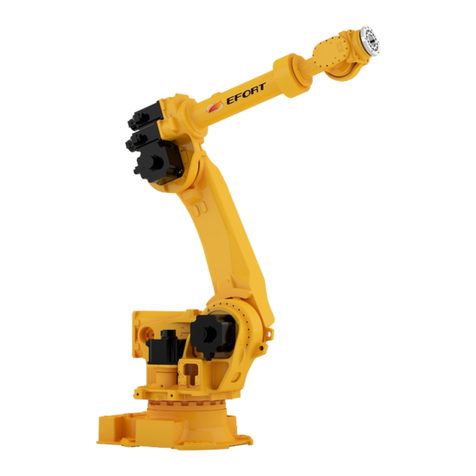
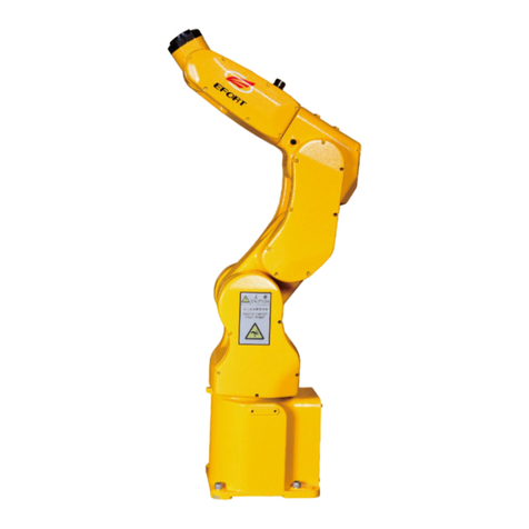
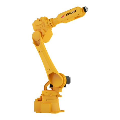
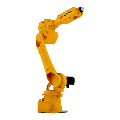
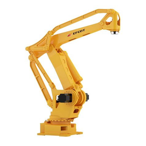
EFORT ER15-1400 User manual

1
ER15-1400 Quick Operation Manual
for Industrial Robot
EFORT Intelligent Equipment Co., Ltd
Service Hotline(Tel):400-0528877

Quick Operation Manual for ER15-1400 Industrial Robot
2
Statement
Thank you for purchasing EFT robot products. In order to ensure that the
products have been set correctly, please read this operation manual carefully
before using this product. The contents mentioned in this statement and the
manual are related to your personal and property safety. If you do not follow the
instructions and warnings in the manual or operate without authorization, it may
cause personal injury to you and the people around you or property damage to
the robot or other objects around you. This statement and manual are the latest
version of this batch of products before leaving the factory. Please visit the
official website, www.efort.com.cn, for updated information.
This manual is only used as a guide for the normal operation of the product.
During the use of the product, EFT will not be liable for personal injury and
property loss caused by other reasons except product defects. EFORT company
solemnly suggests that: personnel participating in robot operation, teaching,
maintenance, repair, spot inspection and other related activities should not be
given permission to operate the robot before completing the training courses
prepared by EFORT company.
Version: V 1.2

Quick Operation Manual for ER15-1400 Industrial Robot
3
Content
Chapter 1 Safety.................................................................................................................................................5
1.1 Safety instruction......................................................................................................................................... 5
1.2 Safety Regulations....................................................................................................................................... 5
1.3 Safety precautions in the process of work................................................................................................... 7
1.3.1 Safety of robot installation and connection.............................................................................................. 7
1.3.2 Safety before robot starting.......................................................................................................................8
1.3.3 Safety of robot starting............................................................................................................................. 9
1.3.4 Test run safety......................................................................................................................................... 10
1.3.5 Safety in teaching process.......................................................................................................................10
1.3.6 Security in auto-run.................................................................................................................................12
1.3.7 Safety during maintenance......................................................................................................................13
1.3.8 Safety during spot check and maintenance.............................................................................................14
Chapter 2 Handling and Installation................................................................................................................ 17
2.1 Overview....................................................................................................................................................17
2.2 Basic Description....................................................................................................................................... 17
2.2.1 Unpacking list......................................................................................................................................... 17
2.2.2 Preparation work before installation.......................................................................................................18
2.2.3 Robot storage environment.....................................................................................................................19
2.2.4 Robot operation environment................................................................................................................. 19
2.2.5 Start robot in cold environment.............................................................................................................. 19
2.2.6 Table of robot performance parameters..................................................................................................19
2.2.7 Robot workplace..................................................................................................................................... 21
2.2.8 Working space of control cabinet........................................................................................................... 21
2.3 Handling.....................................................................................................................................................23
2.3.1 Precautions for robot handling................................................................................................................23
2.3.2 Auxiliary handling tool........................................................................................................................... 24
2.3.3 Robot body handling...............................................................................................................................26
2.3.4 Handling the Control Cabinet.................................................................................................................29
2.4 Installing the Robot....................................................................................................................................30
2.4.1 Setting up a Safety Fence........................................................................................................................30
2.4.2 Robot installation method.......................................................................................................................30
2.4.3 Ground installation..................................................................................................................................31
2.4.4 Bracket installation................................................................................................................................. 32
2.4.5 Upside Down Mounting..........................................................................................................................33
2.4.6 Installation site and environment............................................................................................................33
2.4.7 Integrated application installation interface........................................................................................... 34
Chapter 3 Electrical connection.......................................................................................................................37
3.1 Robot power supply................................................................................................................................... 37
3.2 Connecting cables between the robot control cabinet and the robot body................................................38
3.2.1 The IO cable of the robot body base.......................................................................................................39
3.2.2 The IO cable of the robot body arm........................................................................................................41
Quick Operation Manual for ER15-1400 Industrial Robot
4
3.3 Local IO definition of controller................................................................................................................42
3.4 User external IO functional module.......................................................................................................... 45
3.4.1 The function of converting PNP to NPN................................................................................................45
3.4.2 User external IO terminal block............................................................................................................. 49
3.5 IO module extension.................................................................................................................................. 51
3.6 External safety interface............................................................................................................................ 52
Chapter 4 Quick operation...............................................................................................................................56
4.1 Teaching pendant....................................................................................................................................... 56
4.1.1 About teaching pendant.......................................................................................................................... 56
4.1.2 Function area and interface.....................................................................................................................57
4.1.3 How to hold the teaching pendant.......................................................................................................... 59
4.2 Power on and start......................................................................................................................................60
4.3 Jog operation.............................................................................................................................................. 61
4.3.1 What is jog operation.............................................................................................................................. 61
4.3.2 Points for attention on jog operation...................................................................................................... 61
4.3.3 Start jog operation...................................................................................................................................61
4.3.4 Joint coordinate system - jog operation..................................................................................................62
4.4 Running a Program.................................................................................................................................... 63
4.4.1 What is running a program?....................................................................................................................63
4.4.2 Precautions in running a program...........................................................................................................63
4.4.3 Starting to run a program........................................................................................................................63
4.5 Shut down and power off...........................................................................................................................65
Chapter 5 Common faults and investigation methods during installation...................................................... 67

Quick Operation Manual for ER15-1400 Industrial Robot
5
Chapter 1 Safety
1.1 Safety instruction
According to relevant national and local laws, regulations, and rules, safety precautions are the most
basic concern when using industrial systems including robots.
In the accidents of personal injury and property damage caused by the use of robots, factories using
robots are responsible. Therefore, in addition to understanding this manual and related materials, you must
understand all laws and standards related to health and safety, and be sure to follow them.
For safety, compliance with the requirements of this manual and other EFORT manuals is only a
minimum requirement. As a general rule, the safety-related information recorded in this manual does not
fully cover all aspects of the robot application system. Therefore, when using the robot, the necessary
safety measures should be taken according to the actual situation of the system and its application
environment, and strictly observed.
The operator must read the following information carefully, especially the safety measures set out in
this chapter.
Users of EFORT industrial robots are responsible for ensuring compliance with applicable safety laws
and regulations in their country or region, and should make sure that the necessary safety equipment used
to protect the robot system operator is reasonably designed and installed correctly. Robot operators must be
familiar with the operation and handling of industrial robots such as those described in the following
applicable documents:
1) Operation Manual for ER Series Robot
2) Electrical Operation and Maintenance Manual for ER15-1400 Industrial Robot
3) Mechanical Operation and Maintenance Manual for ER15-1400 Industrial Robot
This Manual contains all safety instructions contained in the product manuals of the robot and control
cabinet. The robot system shall be well designed and manufactured to allow safe access to all areas where
intervention is necessary during operation, adjustment and maintenance. When it is necessary to work in a
safety-protected space, it must be ensured that the work position can be safely and fully entered.
1.2 Safety Regulations
Prohibitions
1. Do not change or dissemble the protective equipment or safety equipment
arbitrarily.
2. Do not touch a robot in case of waterlogging. Cut off the power and drain off the
water.
3. The operation of an industrial robot must be performed by the professionals who
have received sufficient training and guidance and have read this manual thoroughly.
4. The space around the emergency stop equipment must be emptied in case of an
emergency.

Quick Operation Manual for ER15-1400 Industrial Robot
6
5. Improper materials must not be processed with the robot and improper adjustment
or alteration is forbidden.
6. Those who have not been authorized or who have not received any professional
training regarding the operational risks are not allowed to operate the robot.
7. The robot cannot be operated under the following circumstances:
A robot element is exposed.
The safety equipment is disabled.
The fuse and (or) all or any of the mechanical equipment is disabled.
The workpiece is not qualified.
More than one person is operating the robot at the same time.
8. Any violation of the above-mentioned regulations is strictly forbidden. Any attempt
to load an unoriginal accessory is forbidden in particular.
9. Do not attempt to move the safety protection equipment. Users are responsible to
make sure that the safety protection equipment is fixed properly and runs effectively as
expected.
10. The safety equipment can only be moved in case of maintenance and the standard
maintenance protocols must be followed to ensure the safety of the robot.
Mandatory Measures
1. Ensure that nobody is in the dangerous areas before booting the robot.
2. Ensure that all the operators have received some professional training in operating
and maintaining industrial robots.
3. A supervisor should constantly monitor the status of the running programs and to
make sure that the safety protection program is effective.
4. Maintain the robot as instructed in the manual and keep the robot clean and tidy.
5. Pack the cleaning and maintaining tools in a suitable tool box. Any worker should
wear personal safety protection equipment.
6. An operator should follow the current health and safety codes.
7. Stop the robot in case of shutdown, suspected damage, malfunction or abnormal
noise.
8. Call the firefighters for professional help in case of fire.
9. The door of the control cabinet should always be locked up and the key should be
kept by an electrician.
10. No one is allowed to enter the safety protection area if the power is on.
11. All the suspended safety functions must be restored to normal before the Auto
mode is switched on.

Quick Operation Manual for ER15-1400 Industrial Robot
7
Warning
1. The release of the gravity braking system might lead to falling.
2. Danger might occur when a repairer performs a regular maintenance for the
safety protection equipment. Therefore, caution and preventative measures are advised.
1.3 Safety precautions in the process of work
1.3.1 Safety of robot installation and connection
Danger
For all operations of installation and connection, please strictly observe the following
items and refer to the following national or international standards. The safety function of
the robot is designed according to the safety requirements of industrial robots
(GB11291.1-2011/ISO10218- 1:2006).
1. Before operation, please read and understand all manuals, specifications and other
relevant documents provided by EFORT. In addition, a complete understanding of the
operation, teaching, maintenance and other processes is necessary. At the same time,
confirm that all safety measures are in place and effective.
2. When transporting robots, avoid exceeding the specified height:
Only people with forklift and crane operation qualification are allowed to move or
transport robot body, control cabinet, etc
During transportation, never approach or walk under the lifted robot body or control
cabinet.
Do not stay on the robot body and control cabinet during transportation, and do not
touch or support them manually.
3. Hook the wire rope to the lifting ring as described in the robot lifting diagram, and make
sure that the lifting ring is not loose before operation.
4. When using sling to transfer control cabinet, please remove the teaching pendant and its
support to avoid the cable from hooking other equipment.
5. Before moving the robot, remove all unwanted objects and clean up the access to the
installation location.
6. If it is handled by forklift, please fix the control cabinet to prevent the control cabinet
from dumping.
7. Since the robot is composed of precise components, please protect the robot from
collision and impact.
8. When the main power supply of the installation ground is on, the power cable of the
control cabinet shall not be connected. Otherwise, it will be extremely dangerous and can
cause electric shock. When connecting the input power cable, make sure that the main
power supply is off. Meanwhile, to prevent the input power supply or circuit breaker from
being mis-closed, please place clear off-mark on all power supply units and circuit breakers
to indicate that the inspection or maintenance and maintenance are in progress, and lock or

Quick Operation Manual for ER15-1400 Industrial Robot
8
clamp the main power switch.
9. When the wiring is finished, always shut the cover plate of the input power connection
end. Otherwise, it will be extremely dangerous. If the terminal is touched by mistake,
electric shock may be caused.
10. Place the motor or signal cables connecting the robot into the cable tray to prevent
damage. Also take measures to avoid pressure on them. Do not connect the power supply
until all the connection between the control cabinet and the robot body is completed.
Otherwise, it will be very dangerous, which can lead to electric shock and other accidents.
1.3.2 Safety before robot starting
Danger
The operation of the robot before starting must strictly comply with the following
matters, and refer to the relevant national or international safety standards. The safety
function of the robot is designed according to the safety requirements of industrial robots
(GB11291.1-2011/ISO10218- 1:2006).
1. Before operation, please read and understand all manuals, specifications and other
relevant documents provided by EFORT. In addition, a complete understanding of the
operation, teaching, maintenance and other processes is necessary. At the same time,
confirm that all safety measures are in place and effective.
2. Make sure that the robot’s control cabinet, operation panel and all other control devices
are installed outside the safety protection device (fence). Only in this way can the whole
movement range of the robot be monitored.
3. Confirm that there are no personnel, packaging materials, fixtures or other obstacles
within the range of motion of the robot arm.
4. Eliminate any area between the fixed device and the mobile device that may trap people.
5. Before connecting the power cable, please confirm whether the voltage, frequency and
cable specification of the power supply meet the requirements.
6. Ensure that the control cabinet and surrounding equipment are properly grounded. The
ground wire of robot control cabinet and the ground wire of peripheral equipment should be
grounded separately, instead of being connected together. At the same time, if the external
equipment is equipped with electromagnetic switch, contactor and other devices, please
install power filter or equivalent device on the power-incoming line adjacent to the robot
control cabinet.
7. Before turning on the “power” of the robot, please confirm that the installation of the
robot meets the requirements of robot installation.
8. When the operator operates the robot, he must be equipped with an observer for
monitoring, and the observer must also complete the corresponding training provided by
EFORT company.
9. For application projects (water, compressed air, protective gas, etc.), the system must be

Quick Operation Manual for ER15-1400 Industrial Robot
9
equipped with monitoring instruments, so as to automatically detect the abnormal situation
of water supply and gas supply in time.
10. If the robot will produce the largest amount of waste, metal dust particles, fine particles,
etc. in the process of working, please cover the robot body, robot control cabinet, and
peripheral devices with a suitable cover.
1.3.3 Safety of robot starting
Danger
To start the robot, first connect the power line, and then turn the power switch from
“OFF” to “On”. For these operations, please strictly abide by the following items and refer
to relevant domestic or international standards.
The safety function of the robot is designed according to the safety requirements of
industrial robots (GB11291.1-2011/ISO10218- 1:2006).
Before starting the robot, please make sure that the emergency stop switch works
normally.
1. Before operation, please read and understand all manuals, specifications and other
relevant documents provided by EFORT. In addition, a complete understanding of the
operation, teaching, maintenance and other processes is necessary. At the same time,
confirm that all safety measures are in place and effective.
2. Check the name and function of all switches, displays and signals necessary for robot
operation.
3. Do not enter the security fence unless the robot is powered off. At the same time, before
starting the robot, make sure that all safety protection devices function normally.
4. If there are several operators working together in the robot application system, all
operators and related personnel must know that the robot has been activated before starting
the robot.
5. Before turning “ON” the motor power and starting teaching or automatic operation,
please confirm again that there are no workers or left obstacles in and around the robot
safety fence.
6. When starting the robot and recovering from the fault state, put your hand on the
emergency stop switch after turning on the power supply of the control cabinet, so as to cut
off the power supply of the motor immediately in case of any abnormal situation.
7. Before activating the robot, please confirm again that the following conditions have been
met.
Confirm that the installation status of the robot is correct and stable.
Make sure that all kinds of connections of robot control cabinet are correct, and the
power specifications (power supply voltage, frequency, etc.) meet the requirements.
Make sure that all kinds of application connections (water, compressed air,

Quick Operation Manual for ER15-1400 Industrial Robot
10
protective gas, etc.) are correct and consistent with the specifications and models.
Make sure the connection with peripheral devices is correct.
Please make sure that in addition to using the software motion limit, the mechanical
limit block or limit switch has been installed to limit the motion range of the robot.
When the robot is stopped by the mechanical limit block, please confirm that the
relevant parts have been inspected or the failed mechanical limit block has been
replaced (if necessary).
Confirm that safety measures have been taken: some installation protective devices
have been installed such as safety fences or alarm devices.
Please confirm that the function of safety protection device and interlock is normal.
Confirm that the environmental conditions (temperature, humidity, light, noise,
dust, etc.) meet the requirements, or do not exceed the specifications of the system and
robot.
1.3.4 Test run safety
Danger
During test run, there may be design error, teaching error and work error in many
elements such as teaching program, fixture, logic controller, etc. Therefore, the safety
awareness must be further improved during the test run.
The following points should be noted during the test run:
1. First, confirm whether the emergency stop button, hold or run switch and other buttons,
switches and signals used to stop the robot are normal. Once a dangerous situation occurs, if
the robot cannot be stopped, it will not be able to prevent the accident.
2. During the test run of the robot, set the operation speed of the robot to low speed (about
5% - 10%) at first, and confirm the teaching action. Confirm the action repeatedly with
about 2-3 cycles. If any problem is found, stop the robot immediately and correct it. After
ensuring that there is no problem, gradually increase the speed (50% → 70% → 100%), and
repeat the confirmation action again with about 2-3 cycles.
1.3.5 Safety in teaching process
Danger
EFORT recommends that teaching should be completed outside the safety fence.
However, if it is necessary to enter the safety fence, please strictly observe the following
items, and refer to the following domestic or international safety standards.
The safety function of the robot is designed according to the safety requirements of
industrial robots (GB11291.1-2011/ISO10218- 1:2006).
Please confirm that the emergency stop switch is functioning normally before teaching.

Quick Operation Manual for ER15-1400 Industrial Robot
11
1. Please read and understand all manuals, specifications and other relevant documents
provided by EFORT before operation. In addition, a complete understanding of operation,
teaching, maintenance and other processes is necessary. At the same time, confirm that all
safety measures are in place and effective.
2. Before starting the robot, please confirm that all safety guards (safety fences) are
working normally.
3. Teaching should be done by two people, one instructor and one observer. The observer
also bears the responsibility of safety supervision, and confirms the signal conditions such
as “work start” before teaching.
4. Before entering the safety fence, the instructor must set the teaching switch on the
teaching pendant to the manual position to prevent the switch on control cabinet turning to
the automatic mode and cause accidents. Once the robot makes any abnormal movement,
press the emergency stop switch immediately and exit the robot working area from the
preset retreat path immediately.
5. Please install an emergency stop switch for the observer outside the security fence in a
position where the entire robot movement can be monitored. Once the robot is moving
improperly, the observer must be able to press the switch very easily to stop the robot
immediately. In addition, if you need to restart the robot after an emergency stop, reset and
restart manual operation outside the safety fence. The instructor and observer must be
qualified personnel who have been specially trained.
6. Please clearly mark that teaching is in progress to avoid any robot system device being
mis-operated by anyone through control cabinet, operation panel, teach pendant, etc.
7. After completing the teaching work, before confirming the movement track and teaching
data of teaching, please clear all personnel and obstacles left in the safety fence and around
the robot. After confirming that there are no personnel and obstacles left in the safety
fence, please perform the confirmation work outside the safety fence. At this time, the
speed of the robot shall be less than or equal to the safe speed (250mm/s), until the
movement is confirmed to be normal.
8. If you need to restart the robot after an emergency stop, reset and restart manually
outside the safety fence. Meanwhile, confirm all safety conditions and confirm that there
are no personnel and obstacles left around the robot and in the safety fence.
9. During the teaching process, please confirm the range of motion of the robot and
prohibit the approach to the lower part of the robot arm. Avoid the danger caused by
accidental operation. Pay special attention to the danger caused by accidental falling of the
workpiece and prohibit approaching the robot arm when the robot claw holds the
workpiece.
10. For safety, in teaching or inspection mode, the maximum speed of the robot is limited
to 250mm/s (safe operation speed). However, when the operator verifies the teaching data
after the teaching or the error recovery is completed, please set the speed of inspection

Quick Operation Manual for ER15-1400 Industrial Robot
12
operation as low as possible.
11. During the teaching process, whether for the instruction operator or supervisor, the
robot must be monitored for abnormal movement, possible collision and extrusion points
around the robot. Also, please confirm the safety access for the instruction operator to
retreat in case of emergency.
12. After movement teaching of the robot is completed, please set the software limit of the
robot a little beyond the teaching range of the robot. For how to set the software limit, refer
to the operation manual of EFORT industrial robot.
1.3.6 Security in auto-run
Danger
As the teaching program will run at high speed, please strictly abide by the following
items and refer to the relevant international and domestic safety standards.
The safety function of the robot is designed according to the safety requirements of
industrial robots (GB11291.1-2011/ISO10218- 1:2006).
Before automatic operation, please make sure that all switches function normally.
1. Before operation, please read and understand all manuals and other relevant documents
provided by EFORT. In addition, a complete understanding of the operation, teaching,
maintenance and other processes is necessary. At the same time, confirm that all safety
measures are in place and effective.
2. Never enter or partially enter the safety fence during automatic operation. At the same
time, please make sure there are no people or obstacles left in the safety fence before
starting the robot.
3. In automatic operation, the robot looks like it has stopped when waiting for timer delay
or external signal input. But at this time do not get close to the robot, because when the
timer reaches the time or external signal receives the input, the robot will immediately
resume operation.
4. In the automatic operation, this situation will be extremely dangerous: if the grip of the
workpiece is not enough, the workpiece may be thrown off in the movement of the robot.
Please make sure that the workpiece is firmly grasped. When the workpiece is grasped by
pneumatic gripper, electromagnetic mechanism method, etc., please use the
failure-prevention safety system to ensure that once the driving force of the mechanism is
suddenly disconnected, the workpiece will not be ejected. Even in the case of error, the
possibility of the workpiece out is the smallest, please also install protective fence, such as
mesh cover, etc.
5. Display the sign of “automatic operation” on the safety fence and do not enter the work
area. At the same time, please confirm the safe passage for the operator to withdraw in case
of emergency.
6. If the robot stops in automatic operation due to fault, please check the fault information

Quick Operation Manual for ER15-1400 Industrial Robot
13
displayed, and recover and restart the robot according to the correct fault recovery
sequence.
7. Before restarting the robot, please confirm that the safe working conditions are met after
the fault recovery sequence and that there are no personnel, fixtures, peripheral devices or
obstacles left in the safety protection device or around the robot.
1.3.7 Safety during maintenance
Danger
To carry out maintenance, please strictly abide by the following terms, and refer to the
relevant international and domestic safety standards.
The safety function of the robot is designed according to the safety requirements of
industrial robots (GB11291.1-2011/ISO10218- 1:2006).
Please make sure that all switches are working properly before maintenance.
1. Before operation, please read and understand all manuals and other relevant documents
provided by EFORT. In addition, a complete understanding of the operation, teaching,
maintenance and other processes is necessary. At the same time, confirm that all safety
measures are in place and effective.
2. Before entering the security fence, please make sure that all necessary security measures
are ready and functioning well.
3. Before entering the security fence, please cut off from the control power to the main
power supply. Clear signal display should be placed to show that the power is off and
maintenance is in progress, and the main power switch should be locked or clamped to
prevent someone from turning on the power by mistake.
4. The maintenance work is limited to the personnel who have completed the special
training of the corresponding type of robot.
5. Before maintenance, make sure there is enough space around the robot to avoid
interference with peripheral equipment. At the same time, set the peripheral devices to a
fixed state to prevent any sudden motion.
6. Be sure to turn off the automatic operation function before entering the safety fence. If
the robot has any abnormal movement, operators should immediately press the emergency
stop switch and withdraw from the specified evacuation route.
7. In addition to the emergency stop switch of the teaching pendant in the hands of the
operator, please install another emergency stop switch for the inspector outside the safety
bar, where it is convenient to observe the movement range of all robots. In case of
abnormal action of the robot during maintenance, the switch must be easily pressed by the
inspector. After the emergency stop, please reset and restart the robot from outside the
fence. In addition, both operators and inspectors must be personnel who have completed
special training courses.

Quick Operation Manual for ER15-1400 Industrial Robot
14
8. During the operation, both the operator and the inspector must pay attention to the
abnormal movement, the possible collision point and the surrounding of the robot.
9. When replacing, please use only the parts provided by EFORT company.
10. Support the robot arm with a suitable lifting device before removing the servo motor of
any joint axis. If the motor is removed, the brake mechanism of the axis will fail. If there is
no reliable support, the arm will fall. Please note that if you press any axle brake release
switch on the control cabinet, the same danger will appear.
11. When the driver module and power module need to be replaced, please turn off the
control power and wait for at least 7 minutes. Then, please confirm that the output voltage
of the power supply is 0V before starting to replace the work, remove the connector, etc.
Please also note that do not touch any parts to prevent electric shock or scald.
12. If compressed air or water is supplied, please cut off the supply source and remove any
residual pressure in the pipeline before maintenance.
13. When the robot expands the additional axis, make sure that the emergency stop signal
of the additional axis is connected in series to the emergency stop circuit of the control
cabinet.
14. When changing the robot parts, it is necessary to confirm the matching degree of the
changing parts and the original parts, and carefully check the schematic diagram, so as to
prevent the wrong wiring from causing damage to the robot control cabinet components or
external components.
1.3.8 Safety during spot check and maintenance
Danger
In order to prevent system failure, please clean, inspect, maintain or replace the parts of
the robot in strict accordance with the following terms. At the same time, refer to the
relevant international and domestic safety standards.
Before inspection and maintenance, please make sure that all emergency stop switches
function normally.
1. Before operation, please read and understand all manuals and other relevant documents
provided by EFORT. In addition, a complete understanding of the operation, teaching,
maintenance and other processes is necessary. At the same time, confirm that all safety
measures are in place and effective.
2. Before inspection and maintenance, remove unwanted objects and clear the passage to the
installation position.
3. The spot inspection and maintenance work are limited to the personnel who have
completed the special training of the robot or the same type of robot.
4. Before spot check and maintenance, please make sure there is enough space around the
robot to avoid interference with peripheral equipment. At the same time, set the peripheral

Quick Operation Manual for ER15-1400 Industrial Robot
15
devices to a fixed state to prevent any sudden motion.
5. Before entering the safety fence, please cut off the power supply of the whole line or
robot according to the work needs, and cut off from the power supply to the total power
supply. Clear signal shall be placed to show that the power is off, inspection or maintenance
is in progress, and the main power switch shall be locked or clamped by lock, so as to avoid
someone turning on the power by mistake. If the whole line cannot be stooped, install a
temporary safety fence between the target robot and any adjacent robots.
6. When carrying out spot inspection and maintenance of interlocking signal line, please
turn off the power supply of all signal associated equipment to ensure safety. Do not enter
the safety fence during this work.
After the completion of spot inspection and maintenance, please confirm that the safety
protection devices (safety fence, safety bolt, emergency stop switch, etc.), peripheral
equipment, interlocking lines and other safety devices work normally.
7. In addition to the emergency stop switch held by the operator, please install another
emergency stop switch for the supervisor outside the safety fence. The installation position
should be selected as where all the robot motion ranges can be monitored. If the robot
moves abnormally during maintenance or spot inspection, the supervisor must easily press
the switch. After the emergency stop, the recovery and restart of the robot must be carried
out outside the safety fence. In addition, operators and supervisors must be personnel who
have completed special training courses.
8. Before entering the safety fence, the instructor must turn the teaching mode switch on the
teaching pendant to the manual mode, so as to prevent accidents caused by turning the
cabinet mode switch to the automatic mode. Once the robot makes any abnormal movement,
immediately press the emergency stop switch and exit the robot working area from the
preset retreat path.
9. In the process of spot inspection or maintenance, both operators and supervisors must
always monitor whether the robot has abnormal movement, possible collision, extrusion,
etc. At the same time, please confirm the operator’s safe passage for emergency evacuation.
10. If it is inevitable to remove the safety fence in the process of spot inspection or
maintenance, please provide sufficient safety measures:
Park the robot and peripherals in the right place.
Lock or calibrate the power supply and switch. It must be avoided that anyone turns
on the power supply by mistake or sets the switch to automatic mode by mistake.
After the completion of spot inspection or maintenance, the safety fence shall be
installed again, and all safety measures and safety functions shall be confirmed to be
the same as the original.
11. Please use only the parts approved by EFORT company for replacement. In addition, in
the spot inspection or maintenance, please use the teaching mode and move the robot as low
as possible.
12. When the driver module and power module need to be replaced, please turn off the
control power and wait for at least 7 minutes. Then, please confirm that the output voltage

Quick Operation Manual for ER15-1400 Industrial Robot
16
of the power supply is 0V. After confirming that the output power of DC power supply is
changing to 0V, replace or pull out the connector. In addition, if the robot has just stopped
running, the heat sink or regenerative absorption resistance may still be hot. Therefore, be
careful not to touch any hot parts.
13. Before removing the servo motor from the shaft, firmly support the robot arm with a
suitable lifting device. Removing the motor outside the shaft will disable the brake system
of the shaft, and the arm will fall. In addition, pressing any brake release button on the
control panel will cause the same danger.
14. If the robot must maintain the same pose and attitude before and after maintenance,
please record the pose and attitude data of the robot before replacing parts.
15. At the beginning of the replacement process, when the printed circuit board or cable is
removed, check and record their position, connector number, installation method, setting
data, etc., so that they can be restored as they are. After the connector is inserted, its locking
mechanism must be locked firmly. Also, never touch the connector pin.
16. When the application devices (water, compressed air, protective gas, etc.) are used,
please shut down their supply sources and remove the residual pressure in the pipeline
before spot inspection or maintenance.
17. After repair or maintenance, please make sure that all safety protection devices are
working properly
18. Do not change or modify the robot without permission of the company. In case of
unauthorized modification, EFORT will not be responsible.
19. In the robot arm and control cabinet, a variety of data backup batteries are built in. If the
wrong battery is used, it will cause combustion, overheating, explosion, corrosion, leakage
and so on. Therefore, the following requirements must be strictly observed.
Only use batteries specified by EFORT;
The battery cannot be recharged, disassembled, changed and heated;
Do not discard the battery in water or fire;
The battery with damaged surface may have been short circuited inside and must
not be used again;
Do not use metal, such as wires, to short circuit the positive and negative poles of
the battery. The waste batteries should not be discarded in the garbage of incineration,
landfill and dumping to the ground. When discarding batteries, wrap them in bags to
prevent them from contacting other metals, and handle them correctly according to
local regulations.
20. When the robot expands the additional axis, make sure that the emergency stop signal of
the additional axis is connected in series to the emergency stop link of the control cabinet.
After connecting to the extension axis, it is necessary to test the safety function of the
emergency stop link to ensure that it conforms to the safety control logic. After changing the
safety related components, it is necessary to test the safety function of the emergency stop
link to ensure that it meets the safety control logic.
21. When changing the robot parts, the matching degree between the changing parts and the
original parts must be confirmed, and the schematic diagram must be checked carefully to
prevent the wrong wiring from causing damage to the robot control cabinet components or

Quick Operation Manual for ER15-1400 Industrial Robot
17
external components.
Chapter 2 Handling and Installation
2.1 Overview
This chapter contains assembly instructions and information about installing the ER15-1400 industrial
robot on the job site.
Before starting any installation work, it is very important to check all safety information first! Be sure
to read the safety manual of EFORT robot carefully, as well as the first chapter of this manual. There are
several general safety aspects that must be read in full, as well as more specific safety information about the
dangers and safety risks encountered in performing the operation procedures.
2.2 Basic Description
2.2.1 Unpacking list
1. Before unpacking, please confirm whether the outer package of the product is in good condition.
2. After unpacking, please confirm whether the robot accessories are complete and whether the model
is consistent with the order. In case of missing or wrong parts, please contact the supplier in time.
Table 2-1 Robot packing list
Unpacking list
Serial
number
Name
Configuration type
Qua
ntity
Unit
Remark
1
Robot body
Standard
configuration
1
SET
2
Control cabinet
Standard
configuration
1
SET
3
Electric control cabinet
- robot body connecting
cables
Power cable
1
SET
Standard length 8m, cable
length 16m
4
Encoder cable
1
SET
Standard length 8m, cable
length 16m
5
Ground wire
1
SET
Standard length 8m, cable
length 16m
6
Power line of control
cabinet
Standard
configuration
1
SET
7
control cabinet - robot
body encoder cable
Standard
configuration
1
PC
8
control cabinet - body
Standard
1
PC

Quick Operation Manual for ER15-1400 Industrial Robot
18
Note: The above is the standard configuration list, excluding customized models.
2.2.2 Preparation work before installation
This section is intended for the first time to open the box and install the robot. It also contains useful
information needed in the process of reinstalling the robot later.
Before the robot installation, the following inspection items shall be carried out:
Table 2-2 Precautions before installation
1
Visually check the robot to ensure it is not damaged.
2
Ensure that the lifting device used is suitable for handling the specified robot
weight.
3
If the robot is not directly installed, it must be stored according to the
requirements of the robot storage environment.
4
Ensure that the expected operating environment of the robot meets the
requirements of the robot operating environment.
5
Before transporting the robot to its installation site, please ensure that the site
meets the ground installation requirements.
6
Before moving a robot, please check the stability of the robot.
IO cable
configuration
9
IO cable at the end of
small arm
Standard
configuration
1
PC
10
Direct-attached adapter
for 25 PIN
Standard
configuration
1
PC
11
External IO cable for 25
PIN
Standard
configuration
1
PC
12
Direct-attached adapter
for 50 PIN
Standard
configuration
1
PC
13
Instruction
Standard
configuration
1
SET
14
Final factory
inspection report
Enterprise standard
1
PC
15
Product certification
Enterprise standard
1
PC
16
Robot accessories
Accessory box
1
PC
17
Main power cable of
robot
Standard
configuration
1
SET
has been put in the
accessory box
18
Other
One 10A glass tube fuse

Quick Operation Manual for ER15-1400 Industrial Robot
19
7
After these prerequisites are met, the robot can be transported to its installation
site as described in the following sections.
2.2.3 Robot storage environment
The following table shows the allowed robot storage conditions:
Table 2-3 Robot storage environment
Parameter
Value
Minimum ambient temperature
-40℃
Maximum ambient temperature
+55℃
Maximum ambient humidity
93% RH, no condensation(40℃)
2.2.4 Robot operation environment
The following table shows the allowed robot operation conditions:
Table 2-4 Robot operation environment
Parameter
Value
Minimum ambient temperature
0℃
Maximum ambient temperature
+45℃
Maximum ambient humidity
80% RH, no condensation(40℃)
2.2.5 Start robot in cold environment
This procedure describes how to start a robot in a cold environment. The temperature rise rate must be
adjusted according to the ambient temperature and the operating procedure used. The following table shows
an example of speed adjustment methods:
Table 2-5 Working cycle of starting the robot in cold
Cycle
Speed percentage
3 working cycles
20
5 working cycles
50
5 working cycles
80
5 working cycles
100
2.2.6 Table of robot performance parameters
The following table shows the performance parameters of the robot.

Quick Operation Manual for ER15-1400 Industrial Robot
20
Table 2-6 Parameters of the robot
The following table shows the performance parameters of the control cabinet.
Table 2-7 Control cabinet parameters
Control cabinet
model
EC-S6-2
IP class
IP20
Robot Modal
ER15-1400
Type of Movement
Joint
Control axis
6 Axis
Maximum
operating speed
J1 axis
260°/s
J2 axis
255°/s
J3 axis
210°/s
J4 axis
450°/s
J5 axis
450°/s
J6 axis
700°/s
Maximum range
of motion
J1 axis
±170°
J2 axis
-160°~+90°
J3 axis
-85°~+175°
J4 axis
±190°
J5 axis
±130°
J6 axis
±360°
The maximum active
radius
1420mm
The maximum load of
wrist
15kg
Installation conditions
ground installation, upside down
mounting and wall mounting
Degree of protection
IP65/ IP67(Wrist)
The repeat accuracy
±0.05mm
The body weight
150kg
Other manuals for ER15-1400
2
Table of contents
Other EFORT Robotics manuals

EFORT
EFORT ER15-1400 User manual

EFORT
EFORT ER20-1100 User manual

EFORT
EFORT ER130-4-2800 User manual

EFORT
EFORT ER6-1400 User manual

EFORT
EFORT ER210-2700 User manual

EFORT
EFORT ECR5 Instruction manual

EFORT
EFORT ER3-600 User manual

EFORT
EFORT ER15-1400 User manual

EFORT
EFORT ER7-700 User manual

EFORT
EFORT ER15-4-1600 User manual

EFORT
EFORT ER3-600 User manual

EFORT
EFORT ER15-4-1600 User manual

EFORT
EFORT ER10-3-900 User manual

EFORT
EFORT ER180-4-3200 User manual

EFORT
EFORT ECR5 User manual

EFORT
EFORT ECR5 User manual

EFORT
EFORT ER180-4-3200 User manual

EFORT
EFORT ER6-2000 User manual

EFORT
EFORT EC2-M User manual

EFORT
EFORT ER10-1600 User manual