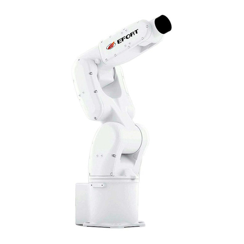
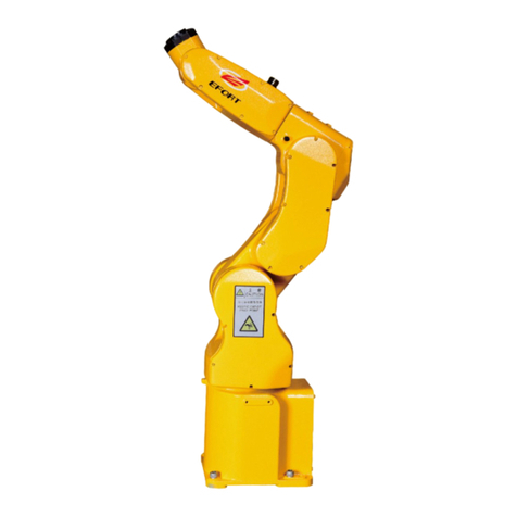
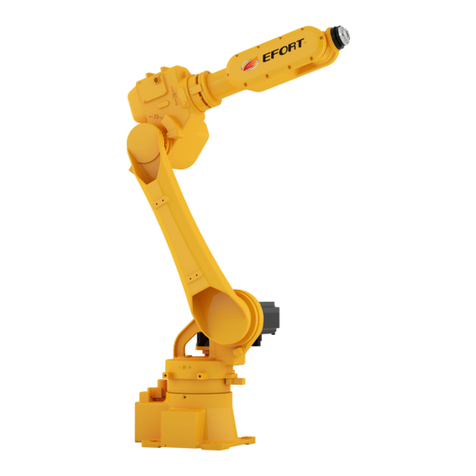
EFORT ER15-4-1600 User manual

ER15-4-1600 Quick Operation Manual
for Industrial Robot
EFORT INTELLIGENT EQUIPMENT CO., LTD
HOT LINE (Tel):+86-400-0528877

Statement
Thank you for purchasing EFORT Robot products. In order to ensure that the product has
been set up correctly, please read this operation manual carefully before using this product.
The contents mentioned in this statement and the manual relate to your personal and property
safety. If you do not follow or do not follow the instructions and warnings of the manual and
operate without permission, it may cause personal injury to you and the people around you or
give EFORT robot or other objects around cause property damage. This statement and the
manual are the latest version as of this batch of products before leaving the factory. Please
follow the official website of www.efort.com.cn for the updated information.
This manual is only used as a guide for the normal operation of the product. During the
use of the product, EFORT will not be liable for personal injury and property damage caused
by reasons other than product defects. EFORT solemnly recommends that: personnel involved
in robot operation, teaching, maintenance, repair, inspection and other related activities should
not give them permission to operate the robot before completing the training courses prepared
by EFORT.
Version:V 1.1

ER15-4-1600 Quick Operation Manual for Industrial Robot
I
Content
Chapter 1 Safety.......................................................................................................................2
1.1 Safety instructions.........................................................................................................2
1.2 Safety guidelines........................................................................................................... 2
1.3 Safety Precautions in Each Work Process.................................................................... 4
1.3.1 Safety of robot installation and connection........................................................4
1.3.2 Safety before starting the robot..........................................................................5
1.3.3 Safety when the robot starts............................................................................... 6
1.3.4 Trial run safety................................................................................................... 7
1.3.5 Safety in teaching...............................................................................................7
1.3.6 Safety during automatic running........................................................................9
1.3.7 Safety during repairing.......................................................................................9
1.3.8 Safety during inspection and maintenance.......................................................11
Chapter 2 Transport and Installation......................................................................................14
2.1 Overview.....................................................................................................................14
2.2 Basic description......................................................................................................... 14
2.2.1 Unpacking list.................................................................................................. 14
2.2.2 Preparations before installation........................................................................14
2.2.3 Robot storage environment.............................................................................. 15
2.2.4 Robot operating environment...........................................................................15
2.2.5 Start the robot in a cold environment...............................................................15
2.2.6 Robot performance parameter table................................................................. 15
2.2.7 Robot workspace..............................................................................................17
2.2.8 Control cabinet working space.........................................................................18
2.3 Transport..................................................................................................................... 19
2.3.1 Robot Transport considerations....................................................................... 19

ER15-4-1600 Quick Operation Manual for Industrial Robot
II
2.3.2 Robot body transport........................................................................................19
2.3.3 Robot control cabinet transport........................................................................21
2.4 Installation...................................................................................................................22
2.4.1 Security bar settings......................................................................................... 22
2.4.2 Robot installation method................................................................................ 23
2.4.3 Ground installation...........................................................................................23
2.4.4 Bracket installation...........................................................................................25
2.4.5 Installation site and environment..................................................................... 25
2.5 Integrated application installation interface............................................................. 25
Chapter 3 Electrical Connection............................................................................................ 27
3.1 Power supply specifications........................................................................................27
3.2 Connection.................................................................................................................. 27
3.3 Introduction to External Emergency Stop...................................................................29
3.4 I/O connection..........................................................................................................30
3.4.1 Controller local IO definition...........................................................................30
3.4.2 Controller local IO expansion.......................................................................... 32
3.4.2 Controller remote IO expansion.......................................................................33
Chapter 4 Quick Operation.................................................................................................... 35
4.1 Teach pendant..............................................................................................................35
4.1.1 About Teach Pendant........................................................................................35
4.1.2 Ribbon and interface........................................................................................ 35
4.1.3 How to hold the teaching pendant....................................................................37
4.2 Power on..................................................................................................................... 38
4.3 Introduction to Coordinate System............................................................................. 38
4.3.1 Industrial robot-joint coordinate system.......................................................... 38
4.3.2 Industrial robot-Cartesian coordinate system...................................................38
4.3.3 Industrial robot-tool coordinate system........................................................... 39

ER15-4-1600 Quick Operation Manual for Industrial Robot
III
4.3.4 Industrial robot-user coordinate system........................................................... 39
4.4 Jog operation............................................................................................................... 39
4.3.1 What is jog operation....................................................................................... 39
4.4.2 Notes on jog operation..................................................................................... 39
4.4.3 Start jog operation............................................................................................ 39
4.4.4 Joint coordinate system-jog operation............................................................. 40
4.4.5 Cartesian coordinate system-jog operation...................................................... 41
4.4.6 Tool coordinate system-jog operation..............................................................41
4.4.7 User coordinate system-jog operation..............................................................42
4.4.8 Jog-fast movement........................................................................................... 42
4.4.9 Jog-slow motion...............................................................................................43
4.4.10 Jog-step movement........................................................................................ 44
4.5 Shut down and power off............................................................................................ 44

ER15-4-1600 Quick Operation Manual for Industrial Robot
第2页
Chapter 1 Safety
1.1 Safety instructions
According to relevant national and local laws, regulations, and rules, safety precautions are the most
basic concern when using industrial systems including robots.
In the accidents of personal injury and property damage caused by the use of robots, factories using
robots are responsible. Therefore, in addition to understanding this manual and related materials, you must
understand all laws and standards related to health and safety, and be sure to abide by them.
For safety, compliance with the requirements of this manual and other EFORT manuals is only a
minimum requirement. As a general rule, the safety-related information recorded in this manual does not
fully cover all aspects of the robot application system. Therefore, when using the robot, the necessary
safety measures should be taken according to the actual situation of the system and its application
environment, and strictly observed.
The operator must read the following information carefully, paying special attention to the safety
measures listed in this chapter.
Users of EFORT industrial robots are responsible for ensuring compliance with applicable safety laws
and regulations in their country/region, and that the necessary safety equipment used to protect the robot
system operator is reasonably designed and installed correctly. Robot operators must be familiar with the
operation and handling of industrial robots such as those described in the following applicable documents:
ER series robot operation manual
ER15-4-1600 Industrial Robot Electrical Operation and Maintenance Manual
ER15-4-1600 Industrial robot mechanical maintenance manual
This manual contains all the safety instructions contained in the product manuals of the robot and
control cabinet. The robot system should be well designed and manufactured to achieve safe access to all
areas necessary for intervention during operation, adjustment and maintenance. For situations where it is
necessary to work in a safe protected space, it is necessary to ensure safe and sufficient access to the
working position
1.2 Safety guidelines
Prohibited behavior
1. Do not arbitrarily modify or dismantle industrial robot protective devices and
safety devices.
2. If waterlogging occurs, do not touch the robot, you should first cut off all power and
drain the site.
3. The operation of industrial robots can only be carried out by professionals who
have received sufficient training and guidance (including those who have read this
manual).
4. Make sure that the emergency stop equipment is unobstructed, and no debris can
be piled up in front of the emergency stop equipment.
5. Do not use inappropriate materials, make inappropriate adjustments and changes
to the robot.
6. Unauthorized personnel, or those who have not received training on the use of

ER15-4-1600 Quick Operation Manual for Industrial Robot
第3页
robots and understand the risks, may not operate the robot.
7. Do not use robots in the following situations:
Robot components exposed
Safety device is disabled
When all or part of the fuses and/or mechanical equipment are disabled
The processed material does not meet the requirements
More than one person is not allowed to use the machine at the same time
8. It is strictly forbidden to use any robot in violation of the above requirements,
especially not to use non-original accessories at will.
9. Do not move the safety protection device. The user is responsible for ensuring that
the safety protection device is fixed and operating in an orderly manner.
10. The safety device can only be moved during maintenance, but the operating
procedures of the maintenance personnel must be followed, and the safety of the robot
must be ensured.
Mandatory measures
1. Before starting the machine, make sure that no one is in the danger zone.
2. All operators must receive special training on the use and maintenance of industrial
machines.
3. The foreman should continue to monitor to ensure that all procedures are running
properly and ensure that the safety protection procedures are properly applied.
4. Carry out maintenance according to the maintenance requirements in this manual
to keep the industrial robot clean and tidy.
5. A suitable tool box should be prepared to summarize cleaning tools and
maintenance tools; staff must wear the personal protective equipment.
6. In addition to these instructions, the tester must also comply with current health
and safety regulations.
7. When the robot malfunctions, or is suspected of being damaged, the machine is not
running, or the machine makes abnormal noise, the machine should be stopped.
8. Once you find that the machine has a fire (regardless of the size of the fire), you
should call the police immediately and find a professional team to fight it.
9. The door of the control cabinet must be closed and not open when the machine is in
operation. Control cabinet keys must be kept by electricians.
10. When operating in the power-on mode, personnel shall not enter the safety
protection area.
11. Before starting the automatic mode, all temporarily disabled safety functions must
be restored to their normal working state
Warning
1. The release of gravity and the braking device may cause a fall hazard.
2. When the safety protection device is inspected, it may cause danger because the
safety protection device cannot work to protect the maintenance personnel. Therefore,
the maintenance personnel must be very careful and take full protective measures

ER15-4-1600 Quick Operation Manual for Industrial Robot
第4页
1.3 Safety Precautions in Each Work Process
1.3.1 Safety of robot installation and connection
Danger
For all operations of installation and connection, please strictly observe the following
items and refer to the following national/international standards. The robot complies
with the safety requirements for robots used in industrial environments
(GB11291.1-2011/ISO10218-1:2006) for the design of safety functions.
1. Before operation, please read and understand all manuals, specifications and other
related documents provided by EFORT. In addition, a complete understanding of
operations, teaching, maintenance and other processes. At the same time, confirm that
all safety measures are in place and effective.
2. When transporting the robot, avoid exceeding the specified height:
Only people with forklift and crane operating qualifications are allowed to
move/transport the robot body, control cabinet, etc.
During transportation, never approach or walk under the lifted robot body or
control cabinet.
Do not stay on the robot body or control cabinet during transportation, and never
touch or support them manually.
3. Hook the wire rope to the hoisting ring as described in the robot lifting diagram, and
confirm that the hoisting ring is not loose before operation.
4. When using the sling to transfer the control cabinet, please remove the teach
pendant and its bracket to prevent the cables from hooking other equipment.
5. Before transporting the robot, please remove all unnecessary objects and clear the
passage to the installation location.
6. If it is transported by a forklift, please fix the control cabinet to prevent it from
tipping over.
7. Since the robot is composed of sophisticated components, please protect the robot
from collision and impact.
8. When the main power supply of the installation site is turned on, the power cable of
the control cabinet must not be connected. Otherwise it will be extremely dangerous
and may cause electric shock. When connecting the input power cable, make sure that
the main power is off. At the same time, in order to prevent the input power or circuit
breaker from being turned on by mistake, please place a clear cut-off mark on all
power supply units and circuit breakers to indicate that inspection/maintenance and
repair are in progress, and lock the main power supply with a lock or place a chuck
switch.
9. When the wiring work is completed, be sure to cover the cover plate of the input
power connection end. Otherwise it will be extremely dangerous. If you touch the
terminal by mistake, it may cause electric shock.
10. Please place the motor/signal cable connecting the robot in the cable groove to
prevent damage. Please also take measures to prevent them from being stressed. Do
ER15-4-1600 Quick Operation Manual for Industrial Robot
第5页
not connect to the power supply until all the connections between the control cabinet
and the robot body are completed. Otherwise it is very dangerous and can cause
accidents such as electric shock.
1.3.2 Safety before starting the robot
Danger
The operation before starting the robot must strictly comply with the following items,
and please refer to the relevant domestic/international safety standards. The robot
complies with the safety requirements for robots used in industrial environments
(GB11291.1-2011/ISO10218-1:2006) for the design of safety functions.
1. Before operation, please read and understand all manuals, specifications and other
related documents provided by EFORT. In addition, a complete understanding of
operations, teaching, maintenance and other processes. At the same time, confirm that
all safety measures are in place and effective.
2. Be sure to install the robot's control cabinet, operation panel and all other control
devices outside the safety guard (fence), only in this way can the entire robot's motion
range be monitored.
3. Confirm that there are no persons, packaging materials, fixtures or other obstacles
in the range of motion of the robot arm.
4. Eliminate any areas where people may be trapped between fixed equipment and
mobile equipment.
5. Before connecting the power cable, please confirm whether the voltage, frequency,
and cable specifications of the power supply meet the requirements.
6. Ensure that the control cabinet and peripheral equipment are properly grounded.
The grounding wire of the robot control cabinet and the grounding wire of the
peripheral equipment should be grounded separately and cannot be connected
together. At the same time, if electromagnetic switches, contactors and other devices
are added to the external equipment, please install a power filter or equivalent device
on the power inlet of the adjacent robot control cabinet.
7. Before turning on the “power” of the robot, please confirm that the installation of
the robot meets the requirements of the robot installation.
8. When the operator operates the robot, an observer must be configured for
monitoring, and this observer must also complete the corresponding training of
EFORT.
9. For application items (water, compressed air, protective gas, etc.), the system must
be equipped with monitoring instruments to automatically detect abnormalities in
water supply and gas supply in time.
10. If the largest scraps, metal dust particles, fine particles, etc. are generated during
the working process of the robot, please cover the robot body, robot control cabinet,
and peripheral devices with a suitable cover

ER15-4-1600 Quick Operation Manual for Industrial Robot
第6页
1.3.3 Safety when the robot starts
Danger
To start the robot, first connect the power cord, and then turn the power switch from
OFF to ON. For these operations, please strictly abide by the following items and refer
to relevant domestic/international standards.
The robot complies with the safety requirements for robots used in industrial
environments (GB11291.1-2011/ISO10218-1:2006) for the design of safety functions.
Before starting the robot, make sure that the emergency stop switch is working
properly.
1. Before operation, please read and understand all manuals, specifications and other
related documents provided by EFORT. In addition, a complete understanding of
operations, teaching, maintenance and other processes. At the same time, confirm that
all safety measures are in place and effective.
2. Check the names and functions of all switches, displays and signals necessary for
robot operation.
3. Do not enter the safety fence unless the power supply of the robot is disconnected. At
the same time, confirm that the safety protection devices function normally before
starting the robot.
4. If there are several operators working together in the robot application system,
make sure that all operators and related personnel know that the robot has been
activated before starting the robot.
5. Before turning on the motor power, starting teaching or automatic operation, please
reconfirm that there are no workers or remaining obstacles in the robot safety fence or
around the robot.
6. When starting the robot and resuming operation from a faulty state, please put your
hand on the emergency stop switch after turning on the power of the control cabinet,
so that you can immediately cut off the power of the motor in the event of an abnormal
situation.
7. Before activating the robot, please reconfirm that the following conditions are met.
Confirm that the installation status of the robot is correct and stable.
Confirm that all connections of the robot control cabinet are correct, and the
power supply specifications (power supply voltage, frequency, etc.) meet the
requirements.
Confirm that various application connections (water, compressed air,
shielding gas, etc.) are correct and consistent with specifications and models.
Confirm that the connections with peripheral devices are correct.
Please confirm that in addition to the software motion limit, a mechanical
limit block/or limit switch has been installed to limit the robot's motion
range.
When the robot is stopped by a mechanical limit stop, please make sure to
check the relevant parts or replace the failed mechanical limit stop (if
necessary).

ER15-4-1600 Quick Operation Manual for Industrial Robot
第7页
Confirm that safety measures have been taken: safety fences or alarm devices
and interlocking signals have been installed to install protective devices.
Please confirm that the safety protection device and interlock function
normally.
Confirm that the environmental conditions (temperature, humidity, light,
noise, dust, etc.) meet the requirements, or that they do not exceed the system
and robot specifications
1.3.4 Trial run safety
Danger
During commissioning, there may be design errors, teaching errors, and working
errors in various elements such as teaching programs, fixtures, and logic controllers.
Therefore, safety awareness must be further improved during test runs.
The following points need to be paid attention to during the test run:
1. First, confirm whether the buttons, switches, and signals used to stop the robot, such
as emergency stop button, hold/run switch, etc., operate normally. Once a dangerous
situation occurs, if the robot cannot be stopped, the accident will not be prevented.
2. When testing the robot, first set the operating speed of the robot to a low speed
(about 5% to 10% speed) to confirm the teaching action. Check the operation
repeatedly in about 2 to 3 cycles. If a problem is found, stop the robot immediately and
make corrections. After ensuring that there is no problem, gradually increase the speed
(50%→70%→100%), and repeat the confirmation action again in about 2 to 3 cycles
each.
1.3.5 Safety in teaching
Danger
EFORT recommends that the teaching work should be completed outside the safety
fence. But if you really need to enter the safety fence, please strictly observe the
following items and refer to the following domestic/international safety standards.
The robot complies with the safety requirements for robots used in industrial
environments (GB11291.1-2011/ISO10218-1:2006) for the design of safety functions.
Before teaching work, please confirm that the emergency stop switch functions
normally.
1. Before operation, please read and understand all manuals, specifications and other
related documents provided by EFORT. In addition, a complete understanding of
operations, teaching, maintenance and other processes. At the same time, confirm
that all safety measures are in place and effective.
2. Before starting the robot, please confirm that all safety protection devices (safety
fences) are working properly.
3. The teaching work should be done by two people, one instructor and one observer.
The observer also assumes the responsibility of safety supervision; and before
teaching, confirm the signal conditions such as "work start".

ER15-4-1600 Quick Operation Manual for Industrial Robot
第8页
4. Before entering the safety fence, the teacher must turn the teaching switch on the
teach pendant to the manual position to prevent accidents caused by the control
cabinet mode switch being turned to automatic mode. Once the robot makes any
abnormal movement, immediately press the emergency stop switch and immediately
exit the robot working area from the preset retreat path.
5. Please install an emergency stop switch for the observer outside the safety fence
where the movement of the entire robot can be monitored. Once the robot moves
incorrectly, the observer must be able to press the switch very conveniently to stop
the robot immediately. In addition, if you need to restart the robot after an
emergency stop, please reset and restart manually outside the safety fence.
Demonstrators and observers must be specially trained and qualified personnel.
6. Please clearly indicate that the teaching work is in progress, so as to prevent people
from misusing any robot system devices through the control cabinet, operation panel,
and teaching pendant.
7. After completing the teaching work, before confirming the teaching movement
trajectory and teaching data, please clear all the people and obstacles left in the safety
fence and around the robot. After confirming that there are no people and obstacles
left in the safety fence, Please perform confirmation work outside the safety fence. At
this time, the speed of the robot should be less than or equal to the safe speed
(250mm/s) until the movement is confirmed to be normal.
8. If you need to restart the robot after an emergency stop, please reset and restart
manually outside the safety fence. At the same time, confirm all safety conditions and
confirm that there are no people and obstacles left around the robot or in the safety
fence.
9. During the teaching process, please confirm the movement range of the robot, and
it is forbidden to approach the bottom of the robot arm. To prevent the danger
caused by accidental operation, pay special attention to the prohibition of
approaching the robot arm when there is a workpiece in the robot's claws to prevent
the danger caused by accidental falling of the workpiece.
10. For safety, the maximum speed of the robot is limited to 250mm/s (safe operating
speed) in the teaching or inspection mode. However, when the operator verifies the
teaching data just after the completion of teaching or error recovery, please set the
check operation speed as low as possible.
11. During the teaching process, both the teaching operator and the supervisor must
always monitor the robot for abnormal movements, possible collisions and squeezing
points in the robot and its surroundings. At the same time, please confirm the safe
passage for the teaching operator for retreat in an emergency.
12. After the robot's motion teaching is completed, please set the robot's software
limit to a little bit outside the robot's teaching motion range. How to set the software
limit, please refer to the EFORT Industrial Robot Operation Manual

ER15-4-1600 Quick Operation Manual for Industrial Robot
第9页
1.3.6 Safety during automatic running
Danger
Since the taught program will run at high speed, please strictly observe the following
items and refer to the relevant international and domestic safety standards.
The robot complies with the safety requirements for robots used in industrial
environments (GB11291.1-2011/ISO10218-1:2006) for the design of safety functions.
Before automatic operation, please confirm that all switches function normally.
1. Before operation, please read and understand all manuals and other related
documents provided by EFORT. In addition, a complete understanding of operations,
teaching, maintenance and other processes. At the same time, confirm that all safety
measures are in place and effective.
2. In automatic operation, never enter or part of the body enters the safety fence. At
the same time, please confirm that there are no people or obstacles left in the safety
fence before starting the operation of the robot.
3. In automatic operation, the robot looks like it has stopped while waiting for the
timer delay or external signal input. But do not approach the robot at this time,
because when the timer expires or an external signal is input, the robot will
immediately resume operation.
4. In automatic operation, this situation will be extremely dangerous: if the gripping
force of the workpiece is insufficient, the workpiece may be thrown off during the
robot movement. Be sure to confirm that the workpiece is firmly grasped. When the
workpiece is grasped by pneumatic grippers, electromagnetic mechanism, etc., please
use a fail-safe system to ensure that the workpiece will not be ejected once the driving
force of the mechanism is suddenly disconnected. Even in the event of an error, when
the possibility of the workpiece coming out is minimal, please install a protective grid
such as a net cover.
5. Display the "automatic running" sign on the safety fence and do not enter the work
area. At the same time, please confirm the safe passage so that the operator can
evacuate in an emergency.
6. If the robot stops during automatic operation due to a fault, please check the
displayed fault information and follow the correct fault recovery sequence to recover
and restart the robot.
7. Please confirm that the safe working conditions are satisfied after the fault recovery
sequence and before restarting the robot, and confirm that there are no people,
fixtures, peripheral devices or obstacles left in the safety protection device or around
the robot
1.3.7 Safety during repairing
Danger
When performing maintenance, please strictly abide by the following terms and refer
to relevant international and domestic safety standards.

ER15-4-1600 Quick Operation Manual for Industrial Robot
第10 页
The robot complies with the safety requirements for robots used in industrial
environments (GB11291.1-2011/ISO10218-1:2006) for the design of safety functions.
Before servicing, please confirm that all switches function normally.
1. Before operation, please read and understand all manuals and other related
documents provided by EFORT. In addition, a complete understanding of operations,
teaching, maintenance and other processes. At the same time, confirm that all safety
measures are in place and effective.
2. Before entering the safety fence, please confirm that all necessary safety measures
have been prepared and functioning well.
3. Before entering the safety fence, please cut off the control power supply all the way
to the main power supply. And place a clear signal to indicate that the shutdown and
maintenance are in progress, and the main power switch is locked or clamped to
prevent someone from turning on the power by mistake.
4. Maintenance work is limited to personnel who have completed special training for
the corresponding model of robot.
5. Before maintenance work, confirm that there is enough space around the robot to
avoid interference with peripheral equipment. At the same time, put the peripheral
devices in a fixed state to prevent them from any sudden movements.
6. Before entering the safety fence, be sure to turn off the automatic operation
function. If there is any abnormal movement of the robot, press the emergency stop
switch immediately and evacuate from the prescribed evacuation route.
7. In addition to the emergency stop switch of the teach pendant in the operator's
hand, please install another emergency stop switch for the inspector outside the safety
fence where it is convenient to observe the full range of movement of the robot. In
case of abnormal actions of the robot during maintenance, this switch must be easily
accessible by the inspector. After an emergency stop, please reset and restart the robot
from outside the fence. In addition, both the operator and the inspector must be
personnel who have completed a special training course.
8. During operation, both the operator and the inspector must always pay attention to
the abnormal movement, possible collision points and the surroundings of the robot.
9. When replacing, please use only the parts provided by EFORT.
10. Before removing any joint axis servo motors, please use a suitable lifting device to
support the robot arm. Removal of the motor will invalidate the brake mechanism of
the shaft. If there is no reliable support, the arm will fall. Please note that if you press
any axis brake release switch on the control cabinet, the same danger will occur.
11. When you need to replace the drive module and power supply module, please turn
off the control power supply and wait at least 7 minutes. Then, please confirm that the
output voltage of the power supply is 0V before starting replacement work and
removing connectors. Please also be careful not to touch any parts to prevent electric
shock or burns.
12. If compressed air or water is supplied, please cut off the supply source and remove
any remaining pressure in the pipeline before maintenance.
13. When the robot expands the additional axis, make sure that the emergency stop

ER15-4-1600 Quick Operation Manual for Industrial Robot
第11 页
signal of the additional axis is connected to the emergency stop circuit of the control
cabinet in series.
14. When changing the robot parts, be sure to confirm the matching degree of the
part and the original part, and carefully check the schematic diagram to prevent the
wrong wiring from causing damage to the robot control cabinet components or
external components
1.3.8 Safety during inspection and maintenance
Danger
To prevent system failure, please clean, inspect, maintain or replace parts of the robot
in strict accordance with the following clauses. Also refer to relevant international and
domestic safety standards.
Before inspection and maintenance, please confirm that all emergency stop switches
function normally.
1. Before operation, please read and understand all manuals and other related
documents provided by EFORT. In addition, a complete understanding of operations,
teaching, maintenance and other processes. At the same time, confirm that all safety
measures are in place and effective.
2. Before inspection and maintenance work, remove unnecessary objects and clear the
passage to the installation location.
3. Inspection and maintenance work is limited to those who have completed special
training for this robot or the same type of robot.
4. Before performing inspection and maintenance work, please confirm that there is
enough space around the robot to avoid interference with peripheral equipment. At the
same time, set the peripheral equipment to a fixed state to ensure that they will not
move suddenly.
5. Before entering the safety fence, please cut off the power supply of the whole line or
robot according to the work needs, and please cut off the power supply until the main
power supply. And place a clear signal to indicate that the shutdown,
inspection/maintenance is in progress, and use a lock to lock or clamp the main power
switch to prevent someone from turning on the power by mistake. If the entire line
cannot be stopped, install a temporary safety fence between the target robot and any
neighboring robots.
6. When performing spot inspection and maintenance of interlocking signal lines,
please turn off the power of all signal-related equipment without error to ensure safety.
During this work, no access to the safety fence is allowed.
After completing the inspection and maintenance work, please confirm that the safety
devices (safety fences, safety pins, emergency stop switches, etc.), peripheral
equipment, interlocking circuits and other safety devices are working properly.
7. In addition to the emergency stop switch held by the operator, please install another
emergency stop switch for the supervisor outside the safety fence. The installation
location should be selected to monitor the full range of movement of the robot. If the

ER15-4-1600 Quick Operation Manual for Industrial Robot
第12 页
robot moves abnormally during maintenance/inspection, the supervisor must easily
press the switch. After an emergency stop, the recovery and restart of the robot must
be carried out outside the safety fence. In addition, operators and supervisors must be
personnel who have completed special training courses.
8. Before entering the safety fence, the teacher must switch the teaching mode switch
on the teach pendant to manual mode to prevent accidents caused by the control
cabinet mode switch being switched to automatic mode. Once the robot makes any
abnormal movement, immediately press the emergency stop switch and immediately
exit the robot working area from the preset retreat path.
9. During the inspection/maintenance process, both the operator and the supervisor
must always monitor the robot for abnormal movements, possible collisions and
squeezing of the robot and its surroundings. At the same time, please confirm the
operator's safe passage for emergency evacuation.
10. If it is unavoidable to remove the safety fence during the inspection/maintenance
process, please provide adequate safety measures:
Park the robot and peripheral equipment in a suitable place.
Locking/calibrating the power supply and switch, must prevent anyone from
turning on the power supply by mistake or turning the switch to automatic mode by
mistake.
After completing the inspection/maintenance, reinstall the safety fence and confirm
that all safety measures and safety functions are the same as the original ones.
11. Please use only the parts approved by EFORT. In addition, during
inspection/maintenance, be sure to use the teaching mode and move the robot at the
lowest possible speed.
12. When you need to replace the drive module and power supply module, please turn
off the control power supply and wait at least 7 minutes. Then, please confirm that the
output voltage of the power supply is 0V. After confirming that the output power of the
DC power supply is becoming 0V, start the work such as replacing or unplugging the
connector. In addition, if the robot just stops running, the heat sink or regenerative
absorption resistor may still be hot. Therefore, be careful not to touch any hot parts.
13. Before removing the servo motor from the shaft, please use a suitable lifting device
to firmly support the robot arm. Removal of the motor outside the shaft will invalidate
the brake system of the shaft and the arm will fall. In addition, pressing any brake
release button on the control panel will cause the same danger.
14. If the robot must maintain the same posture before and after maintenance, please
record the posture data of the robot before replacing parts.
15. At the beginning of the replacement process, when the printed circuit board or
cable is removed, check and record their position, connector number, installation
method, setting data, etc., so that it can be restored as it is. After the connector is
inserted, its locking mechanism must be firmly locked. Also, never touch the pins of the
connector.
16. When the application devices (water, compressed air, protective gas, etc.) are used,
please close their supply sources and clear the remaining pressure in the pipeline

ER15-4-1600 Quick Operation Manual for Industrial Robot
第13 页
before performing inspection/maintenance.
17. After overhaul/maintenance, please confirm that all safety protective equipment
functions normally.
18. Do not change or modify the robot without the permission of the company. In the
event of unauthorized modification, EFORT will not take any responsibility.
19. In the robot arm and control cabinet, there are a variety of built-in data backup
batteries. If the wrong battery is used, it will cause burning, overheating, explosion,
corrosion, liquid leakage, etc. Therefore, the following requirements must be strictly
observed.
Only use batteries specified by EFORT;
The battery cannot be recharged, disassembled, changed or heated;
Do not discard the battery in water or fire;
Batteries with damaged surfaces may have been short-circuited inside and should
never be used again;
Do not use metals, such as wires, to short-circuit the positive and negative electrodes
of the battery. Do not discard used batteries in garbage that is incinerated, landfilled,
or dumped on the ground. When disposing of batteries, please wrap them in a bag to
prevent them from contacting other metals. At the same time, please dispose of them
properly in accordance with local regulations.
20. When the robot expands the additional axis, make sure that the emergency stop
signal of the additional axis is connected to the emergency stop link of the control
cabinet in series. After connecting the extended axis, the safety function of the
emergency stop link needs to be tested to ensure compliance with the safety control
logic. After changing the safety-related components, it is necessary to test the safety
function of the emergency stop link to ensure compliance with the safety control logic.
21. When changing the robot parts, be sure to confirm the matching degree of the part
and the original part, and carefully check the schematic diagram to prevent the wrong
wiring from causing damage to the robot control cabinet components or external
components

ER15-4-1600 Quick Operation Manual for Industrial Robot
第14 页
Chapter 2 Transport and Installation
2.1 Overview
This chapter contains assembly instructions and information on installing the ER15-4-1600 robot on
the job site.
Before starting any installation work, it is extremely important to check all the safety information!
Please be sure to read the EFORT Robot Safety Manual carefully, as well as the first chapter of this manual.
There are several general safety aspects that must be read in full, as well as more specific safety
information that introduces the dangers and safety risks encountered when performing operating procedures
2.2 Basic description
2.2.1 Unpacking list
1. Before unpacking, please confirm whether the outer packaging of the product is intact.
2. After unpacking, please confirm whether all parts of the robot are complete and whether the model is
consistent with the order. If you find missing or wrong parts, please contact the supplier in time.
Table 2-1 Robot packing list
Unpacking list
Name
Model
Quantity
Unit
Remarks
Robot body
ER15-4-1600
1
PC
Control cabinet
EC-M4
1
PC
Teach Pendant + Teach
Pendant Cable
11500010563
1
PC
Electric cabinet-body power
line
10900023245
1
SET
It has been installed on the
electric cabinet, the
standard length is 8m, and
it supports custom-made
12m, 16m, 20m
Electric cabinet-body encoder
line
10900023246
1
SET
It has been installed on the
electric cabinet, the
standard length is 8m, and
it supports custom-made
12m, 16m, 20m
Control cabinet power cord
\
1
SET
Installed on the electric
cabinet
Accessories (bracket, pins)
\
1
PC
Installed on the body
Note: The above is a standard configuration list, not including customized models.
2.2.2 Preparations before installation
This section is intended for use when unpacking and installing the robot for the first time. It also
contains useful information needed in the process of reinstalling the robot in the future.
Before installing the robot, check the following items:

ER15-4-1600 Quick Operation Manual for Industrial Robot
第15 页
Table 2-2 Precautions before installation
1
Visually inspect the robot to ensure that it is not damaged.
2
Make sure that the lifting device used is suitable for carrying the specified robot
weight.
3
If the robot is not installed directly, it must be stored according to the robot
storage environment requirements.
4
Ensure that the expected operating environment of the robot meets the
requirements of the robot's operating environment.
5
Before transporting the robot to its installation site, make sure that the site
meets the ground installation requirements.
6
Before moving the robot, please check the stability of the robot.
7
Once these prerequisites are met, the robot can be transported to its installation
site as described in the following section.
2.2.3 Robot storage environment
The following table shows the allowed robot storage conditions:
Table 2-3 Robot storage environment
parameter
值
Minimum ambient temperature
-40℃
Maximum ambient temperature
+55℃
Maximum ambient humidity
93%RH,无凝露(40℃)
2.2.4 Robot operating environment
The following table shows the allowed robot operating conditions:
Table 2-4 Robot operating environment
parameter
值
Minimum ambient temperature
0°C
Maximum ambient temperature
+45°C
Maximum ambient humidity
80%RH,无凝露(40℃)
2.2.5 Start the robot in a cold environment
This procedure describes how to start the robot in a cold environment. The heating rate must be
adjusted according to the ambient temperature and the operating procedures used. The following table
shows examples of speed adjustment methods:
Table 2-5 Start the robot operating cycle in the cold
Working cycles
Percentage of speed
3 working cycles
20
5 working cycles
50
5 working cycles
80
5 working cycles
100
2.2.6 Robot performance parameter table
The following table shows the performance parameters of the robot
Table 2-6 Robot packing list parameter table
Performance parameter table

ER15-4-1600 Quick Operation Manual for Industrial Robot
第16 页
model
ER15-4-1600
Action type
Articulated
Control axis
4Axis
Maximum operating
speed
axis/J1 轴
175°/sec
axis/J2 轴
165°/sec
axis/J3 轴
155°/sec
axis/J4 轴
330°/sec
Maximum motion
range
axis/J1 轴
±165°
axis/J2 轴
-85°/+40
-90º≤J2+J3≤+15°
axis/J3 轴
-70°/+15°(*)
axis/J4 轴
±360°
Maximum radius of activity
1625mm
Maximum load on wrist
15kg
Installation conditions
Ground installation, bracket installation
Protection class
IP65 (wrist body part), IP54 (other parts)
Repeatability
±0.08mm
Body weight
180kg
Note:
(*) The mark is explained as follows
1) The (*) mark of the J3 axis indicates that when the J2 axis is in the state of "-85º≤J3≤+40°", the motion
range of the J3 axis is "-70º≤J3≤+15°".
2) When the J2 axis is at a certain angle within its motion range, the motion range of the J3 axis is based on
its maximum possible motion range-"-70º≤J3≤+100°", while meeting the constraint condition "-85º
≤J2≤+40°&-90º≤J2+J3≤+15° ".
For example:
(1) When the J2 axis is in the state of -85°, the motion range of the J3 axis is "-5º≤J3≤+100°";
(2) When the J2 axis is at -20°, the motion range of the J3 axis is "-70º≤J3≤+35°";
(3) When the J2 axis is at 0°, the motion range of the J3 axis is "-70º≤J3≤+15°";
(4)When the J2 axis is at +40°, the motion range of the J3 axis is "-70º≤J3≤-25°"
The following table shows the performance parameters of the control cabinet
Table 2-7 Control cabinet parameter list
Control cabinet model
EC-M4
IP rating
IP54
IO port
16 digital inputs/16 digital outputs (support expansion)
communication method
TCP/IP、Modbus-TCP、CAN、ProfibusDP、EtherCAT
power supply
AC220V±10%,50/60Hz
size
W555mm×D560mm×H1165mm
weight
89kg
Ambient temperature
0℃~45℃
Other manuals for ER15-4-1600
1
Table of contents
Other EFORT Robotics manuals

EFORT
EFORT ECR5 User manual

EFORT
EFORT ER20-1100 User manual

EFORT
EFORT ER15-4-1600 User manual

EFORT
EFORT ER15-1400 User manual

EFORT
EFORT ER130-4-2800 User manual

EFORT
EFORT ER15-1400 User manual

EFORT
EFORT ECR5 User manual

EFORT
EFORT ER10-1600 User manual

EFORT
EFORT ER15-1400 User manual

EFORT
EFORT ER6-2000 User manual

EFORT
EFORT ER6-1400 User manual

EFORT
EFORT ER12-4-2000 User manual

EFORT
EFORT ER180-4-3200 User manual

EFORT
EFORT ER210-2700 User manual

EFORT
EFORT ER20-1700 User manual

EFORT
EFORT EC2-M User manual

EFORT
EFORT ER180-4-3200 User manual

EFORT
EFORT ER7-700 User manual

EFORT
EFORT ER20-1700 User manual

EFORT
EFORT ER10-3-900 User manual