Eldes ESIM384 User manual

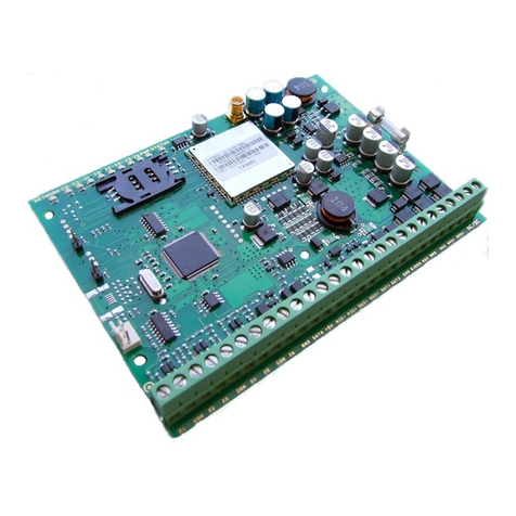
ESIM384
GSM ALARM AND MANAGEMENT SYSTEM
INSTALLATION MANUAL

2
2
EN ESIM384 Installation and Conguration Manual v1.1
Installation Manual v1.0
Valid for ESIM384 v01.00
Safety instructions
Please read and follow these safety guidelines in order to maintain safety of operators and people around:
• GSM alarm & management system ESIM384 (also referenced as “alarm system”, “system” or “device”) has radio transceiver operating in
GSM 850/900/1800/1900 bands.
• DO NOT use the system where it can be interfere with other devices and cause any potential danger.
• DO NOT use the system with medical devices.
• DO NOT use the system in hazardous environment.
• DO NOT expose the system to high humidity, chemical environment or mechanical impacts.
• DO NOT attempt to personally repair the system.
• System label is on the bottom side of the device.
GSM alarm system ESIM384 is a device mounted in limited access areas. Any system repairs must be done only by qualied,
safety aware personnel.
The system must be powered by main 16-24V ~50/60 Hz1.5A max or 18-24V 1,5A max power supply which must be
approved by LST EN 60950-1 standard and be easily accessible nearby the device. When connecting the power supply to the
system, switching the pole terminals places does not have any aect.
Any additional devices linked to the system ESIM384 (computer, sensors, relays etc.) must be approved by LST EN 60950-1
standard.
The power supply can be connected to AC mains only inside installation room with auto-
matic 2-pole circuit breaker capable of disconnecting circuit in the event of short circuit
or over-current condition. Open circuit breaker must have a gap between connections
of more than 3mm (0.12in) and the disconnection current 5A.
Phase
AC 230V
50/60Hz/DC 24V
USB cable
Null
PE
ESIM384
AC/DC
Mains power and backup battery must be disconnected before any installation or tuning work starts. The system installation
or maintenance must not be done during stormy conditions
Backup battery must be connected via the connection which in the case of breaking would result in disconnection of one of
battery pole terminals. Special care must be taken when connecting positive and negative battery terminals. Switching the
pole terminals places is NOT allowed.
In order to avoid re or explosion hazards the system must be used only with approved backup battery.
The device is fully turned o by disconnecting 2-pole switch o device of the main power supply and disconnecting backup
battery connector.
Fuse F1 type – Slow Blown 2A. Replacement fuses have to be exactly the same as indicated by the manufacturer.
If you use I security class computer for setting the parameters it must be connected to earth.

3
3
EN
ESIM384 Installation and Conguration Manual v1.1
Contents
1. GENERAL INFORMATION.........................................................................................................................................................8
1.1. Functionality......................................................................................................................................................................................................8
1.2. Compatible Device Overview...........................................................................................................................................................................8
1.3. Default Parameters and Ways of Parameter Conguration .......................................................................................................................8
2. Technical Specications .......................................................................................................................................................16
2.1. Electrical and Mechanical Characteristics ..................................................................................................................................................16
2.2. Main Unit, LED Indicator and Connector Functionality .............................................................................................................................17
2.3. Wiring Diagrams ..............................................................................................................................................................................................18
3. INSTALLATION ...................................................................................................................................................................... 24
4. GENERAL OPERATIONAL DESCRIPTION............................................................................................................................... 28
5. CONFIGURATION METHODS ................................................................................................................................................. 29
5.1. SMS Text Messages........................................................................................................................................................................................ 29
5.2. EKB2 LCD Keypad............................................................................................................................................................................................ 29
5.3. EKB3/EKB3W/EWKB4 LED Keypads ........................................................................................................................................................... 30
5.4. ELDES Conguration software..................................................................................................................................................................... 30
5.5. System conguration by USB cable..............................................................................................................................................................31
6. SMS PASSWORD AND INSTALLER CODE................................................................................................................................32
7. SYSTEM LANGUAGE ...............................................................................................................................................................33
8. USER PHONE NUMBERS ....................................................................................................................................................... 34
8.1. User Phone Number Names ..........................................................................................................................................................................35
8.2. System Control from any Phone Number....................................................................................................................................................35
9. DATE AND TIME..................................................................................................................................................................... 36
9.1. Automatic Date and Time Synchronization ............................................................................................................................................... 36
10. MASTER AND USER CODES .................................................................................................................................................. 38
10.1. Master and User Code Names ...................................................................................................................................................................... 40
11. IBUTTON KEYS .......................................................................................................................................................................41
11.1. Adding and Removing iButton Keys............................................................................................................................................................ 41
11.2. iButton Key Names......................................................................................................................................................................................... 42
12. ARMING AND DISARMING..................................................................................................................................................... 43
12.1. Free of Charge Phone Call............................................................................................................................................................................. 44
12.2. SMS Text Message.......................................................................................................................................................................................... 44
12.3. EKB2 Keypad and User/Master Code .......................................................................................................................................................... 45
12.4. EKB3 Keypad and User/Master Code .......................................................................................................................................................... 47
12.5. EKB3W/EWKB4 Keypads and User/Master Code...................................................................................................................................... 49
12.6. iButton Key.......................................................................................................................................................................................................51
12.7. EWK1/EWK2 Wireless Keyfob .......................................................................................................................................................................52
12.8. Arm-Disarm by Zone .......................................................................................................................................................................................53
12.9. Automatic Arm/Disarm by Scheduler...........................................................................................................................................................53
12.10. Disabling and Enabling Arm/Disarm Notications ...................................................................................................................................53
13. EXIT AND ENTRY DELAY ........................................................................................................................................................55
14. ZONES.....................................................................................................................................................................................57
14.1. Zone Numbering.............................................................................................................................................................................................57
14.2. Zone Expansion ...............................................................................................................................................................................................57
14.3. 8-Zone Mode....................................................................................................................................................................................................57
14.4. ATZ (Advanced Technology Zone) Mode.................................................................................................................................................... 58
14.5. Zone Type Denitions ................................................................................................................................................................................... 58
14.6. Zone Attributes .............................................................................................................................................................................................. 59
14.7. Bypassing and Activating Zones.................................................................................................................................................................. 63
14.8. Zone Names .................................................................................................................................................................................................... 63
14.9. Disabling and Enabling Zones ..................................................................................................................................................................... 64
14.10. Viewing Zone State ...................................................................................................................................................................................... 65
15. STAY MODE............................................................................................................................................................................ 66
16. TAMPERS................................................................................................................................................................................67
16.1. Tamper Names................................................................................................................................................................................................ 68
17. ALARM INDICATIONS AND NOTIFICATIONS FOR USER ....................................................................................................... 69
17.1. Enabling and Disabling Alarm Notications................................................................................................................................................71
17.2. Audio Files and Introduction Audio..............................................................................................................................................................72
18. PROGRAMMABLE (PGM) OUTPUTS.......................................................................................................................................73
18.1. PGM Output Numbering .................................................................................................................................................................................73
18.2. PGM Output Expansion...................................................................................................................................................................................73
18.3. PGM Output Names.........................................................................................................................................................................................74

4
4
EN ESIM384 Installation and Conguration Manual v1.1
18.4. Disabling and Enabling PGM Outputs...........................................................................................................................................................74
18.5. Turning PGM Outputs ON and OFF................................................................................................................................................................74
18.6. PGM Output Control by Event and Scheduler ............................................................................................................................................ 76
18.6.1. PGM Output Actions and System Events.................................................................................................................................................. 76
18.6.2. Schedulers .....................................................................................................................................................................................................77
18.6.3. Additional Conditions...................................................................................................................................................................................77
18.7. Wireless PGM Output Type Denitions........................................................................................................................................................77
19. WIRELESS DEVICES............................................................................................................................................................... 78
19.1. Pairing, Removing and Replacing Wireless Device ................................................................................................................................... 79
19.2. Wireless Device Information......................................................................................................................................................................... 80
19.3. Wireless Signal Status Monitoring .............................................................................................................................................................. 80
19.4. Disabling and Enabling Siren if Wireless Signal is Lost ............................................................................................................................ 83
19.5. EKB3W/EWKB4 - Wireless LED Keypad...................................................................................................................................................... 83
19.6. EWR2 – Wireless Signal Repeater................................................................................................................................................................ 85
19.7. EWF1/EWF1CO - Wireless Smoke/CO Detector ........................................................................................................................................ 86
19.8. EW2 - Wireless Zone and PGM Output Expansion Module ...................................................................................................................... 88
19.9. EWM1 - Wireless Power Socket.................................................................................................................................................................... 88
19.10. EWKB5 Wireless Touchpad Overview........................................................................................................................................................ 89
20. WIRED SIREN/BELL............................................................................................................................................................. 100
20.1. BELL Output Status Monitoring................................................................................................................................................................. 101
20.2. Bell Squawk................................................................................................................................................................................................... 101
20.3. Bell Squawk in Stay Mode ........................................................................................................................................................................... 102
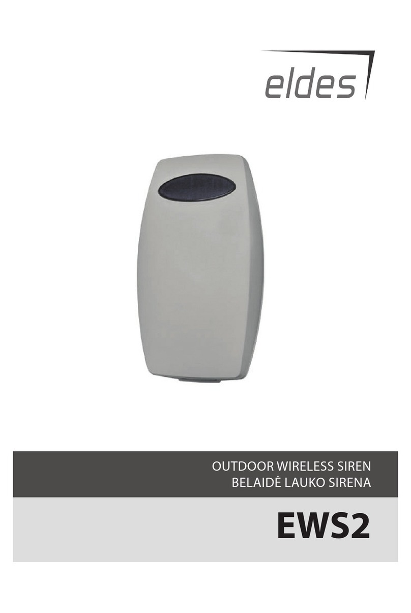
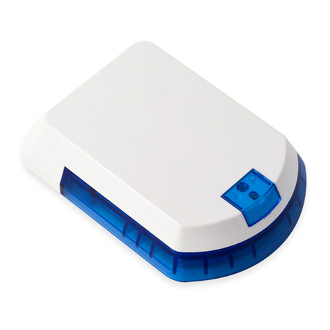
20.4. Indication by EWS2 - Wireless Outdoor Siren Indicators ....................................................................................................................... 103
20.5. Indication by EWS3 - Wireless Indoor Siren Indicators ..........................................................................................................................104
21. BACKUP BATTERY, MAINS POWER STATUS MONITORING AND MEMORY......................................................................... 105
21.1. Backup Battery Status Monitoring ............................................................................................................................................................ 105
21.2. Mains Power Status Monitoring................................................................................................................................................................. 107
22. GSM CONNECTION AND ANTENNA STATUS MONITORING................................................................................................. 109
22.1. GSM Connection Status Monitoring ..........................................................................................................................................................109
22.2. GSM/GPRS antenna Status Monitoring .................................................................................................................................................... 110
23. PARTITIONS .........................................................................................................................................................................111
23.1. Zone Partition ................................................................................................................................................................................................111
23.2. User Phone Number Partition .....................................................................................................................................................................111
23.3. Keypad Partition and Keypad Partition Switch.........................................................................................................................................112
23.4. User/Master Code Partition ....................................................................................................................................................................... 113
23.5. iButton Key Partition ................................................................................................................................................................................... 114
23.6. EWK1/EWK2 Wireless Keyfob Partition ................................................................................................................................................... 114
24. TEMPERATURE SENSORS ....................................................................................................................................................115
24.1. Adding, Removing and Replacing On-Board Dallas Temperature Sensors..........................................................................................115
24.2. Primary and Secondary Temperature Sensors........................................................................................................................................ 116
24.3. Setting Up MIN and MAX Temperature Thresholds. Temperature Info SMS.......................................................................................117
24.4. Temperature Sensor Names....................................................................................................................................................................... 118
25. REMOTE LISTENING AND 2-WAY VOICE COMMUNICATION.................................................................................................119
26. SYSTEM INFORMATION. INFO SMS..................................................................................................................................... 120
26.1. Periodic Info SMS.......................................................................................................................................................................................... 120
27. SYSTEM NOTIFICATIONS .....................................................................................................................................................122
27.1. SMS Text Message Delivery Restrictions ................................................................................................................................................. 133
27.2. SMSC (Short Message Service Center) Phone Number.......................................................................................................................... 133
28. EVENT AND ALARM LOG ..................................................................................................................................................... 134
28.1. Event Log ....................................................................................................................................................................................................... 134
28.2. Alarm Log....................................................................................................................................................................................................... 135
29. INDICATION OF SYSTEM FAULTS ........................................................................................................................................ 136
30. MONITORING STATION........................................................................................................................................................ 138
30.1. Data Messages – Events.............................................................................................................................................................................. 139
30.2. Communication............................................................................................................................................................................................. 145
31. DUAL SIM MANAGEMENT ....................................................................................................................................................157
31.1. Disabled Mode............................................................................................................................................................................................... 157
31.2. Automatic Mode ........................................................................................................................................................................................... 157
32. WIRED DEVICES................................................................................................................................................................... 158
32.1. RS485 Interface ........................................................................................................................................................................................... 158
32.2. 1-Wire Interface............................................................................................................................................................................................ 167
32.3. Modules Interface ........................................................................................................................................................................................ 167
33. SERVICE MODE .................................................................................................................................................................... 170
34. REMOTE SYSTEM RESTART ................................................................................................................................................ 170

5
5
EN
ESIM384 Installation and Conguration Manual v1.1
35. ELDES CLOUD SERVICES ......................................................................................................................................................171
36. TECHNICAL SUPPORT .........................................................................................................................................................172
36.1. Troubleshooting ........................................................................................................................................................................................... 172
36.2. Restoring Default Parameters ................................................................................................................................................................... 172
36.3. Updating the Firmware via USB Cable Locally........................................................................................................................................ 172
36.4. Updating Firmware via GPRS Connection Remotely .............................................................................................................................. 173
36.5. Frequently Asked Questions...................................................................................................................................................................... 173
37. RELATED PRODUCTS............................................................................................................................................................175
38. GLOSSARY – APPENDIX 1.................................................................................................................................................... 178
39. EKB3/EKB3W/EWKB4 COMMANDS - APPENDIX 2 ............................................................................................................ 180
40. SMS COMMANDS - APPENDIX 3 ..........................................................................................................................................191
41. RADIO SYSTEM INSTALLATION AND SIGNAL PENETRATION APPENDIX 4................................................................... 194

6
6
EN ESIM384 Installation and Conguration Manual v1.1
TERMS OF USE
The following terms and conditions govern use of the ESIM384 device and contains important information on limitations regarding the
product’s use and function, as well as information on the limitations of the manufacturer’s liability. Please carefully read these terms and
conditions. For more information on your product, please visit www.eldesalarms.com
TECHNICAL SUPPORT
In order to ensure continuous and proper operation of the ESIM384 device and uninterrupted service, it is the responsibility of the User to
make sure that: (I) the product is properly installed, and (II) there is constant internet or GSM connection and electrical supply (low battery
must be replaced in time).
If you experience diculty during the installation or subsequent use of the system, you may contact ELDES, UAB distributor or dealer in
your country/region. For more information see www.eldesalarms.com
WARRANTY PROCEDURES
Warranty and out of warranty service should be obtained by contacting the system integrator/dealer/retailer/e-tailer or distributor where
the customer purchased the product. When requesting for service, the proof of purchase and the product serial number must be provided.
The return of the defective product should be strictly through the original route of purchase, and the customers shall pack the product
appropriately to prevent the returned product from suering in the transportation.
MANUFACTURER WARRANTY
ELDES provides a limited warranty for its products only to the person or entity that originally purchased the product from ELDES or its
authorized distributor or retailer and only in case of defective workmanship and materials under normal use of the system for a period of
twenty four (24) months from the date of shipment by the ELDES, UAB (Warranty Period). Warranty obligations do not cover expandable
materials (power elements and/or batteries), holders and enclosures. The warranty remains valid only if the system is used as intended,
following all guidelines outlined in this manual and in accordance with the operating conditions specied. The warranty is void if the system
has been exposed to mechanical impact, chemicals, high humidity, uids, corrosive and hazardous environments or force majeure factors.
If a hardware defect arises and a valid claim is received within the Warranty Period, at its own discretion, ELDES, UAB will either (a) repair a
hardware defect at no charge, using new or refurbished replacement parts, or (b) exchange the product with a product that is new or which
has been manufactured from new or serviceable used parts and is at least functionally equivalent to the original product, or (c) refund the
purchase price of the product.
LIMITED LIABILITY
The buyer must agree that the system will reduce the risk of theft, burglary or other dangers but does not provide guarantee against such
events. ELDES, UAB will not assume any responsibility regarding personal or property, or revenue loss while using the system. ELDES, UAB
is not aliated with any of the Internet providers, therefore, it shall not responsible for the quality of Internet service.
ELDES, UAB shall also assume no liability due to direct or indirect damage or loss, as well as unreceived income when using the system, in-
cluding cases, when the damages arise due to the above mentioned risks, when due to breakdown or malfunction the user is not informed
in a timely manner about a risk which has arisen. In any case, the liability of ELDES, UAB, as much as it is allowed by the laws in force, shall
not exceed the price of acquisition of the product.
CONSUMER PROTECTION LAWS
FOR CONSUMERS WHO ARE COVERED BY CONSUMER PROTECTION LAWS OR REGULATIONS IN THEIR COUNTRY OF PURCHASE OR, IF DIF-
FERENT, THEIR COUNTRY OF RESIDENCE, THE BENEFITS CONFERRED BY THIS WARRANTY ARE IN ADDITION TO ALL RIGHTS AND
REMEDIES CONVEYED BY SUCH CONSUMER PROTECTION LAWS AND REGULATIONS. This warranty grants upon you specic legal
rights, and you may also have other rights that vary by country, state or province.
DISPOSAL AND RECYCLING INFORMATION
The WEEE (Waste Electrical and Electronic Equipment) marking on this product (see left) or its documentation indicates that the
product must not be disposed of together with household waste. To prevent possible harm to human health and/or the envi-
ronment, the product must be disposed on in an approved and environmentally safe recycling process. For further information
on how to dispose of this product correctly, contact the system supplier, or the local authority responsible for waste disposal
in your area.

7
7
EN
ESIM384 Installation and Conguration Manual v1.1
Content of Pack
Item Quantity Item Quantity
1. ESIM384.......................... ...................................1
2. SMA antenna..................... ................................2
3. Back-up battery connection wire ..................1
3. User manual.......................................................1
5. Resistors 5,6k.................................................16
6. Resistors 3,3k.................................................8
7. Plastic standos......... ......................................4
These following components are optional (sold separately) and are not included in device’s Content of Pack:
Buzzer;
Microphone.
About Installation Manual
This document describes detailed installation and operation process of alarm system ESIM384. It is very important to read the installation
manual before starting to use the system.
It is strictly forbidden to copy and distribute the information contained in this document or to pass thereof to a third
party without an a priori written authorization obtained from ELDES, UAB. ELDES, UAB reserves the right to update or
modify this document and/or related products without an a priori warning. ELDES, UAB hereby declares that GSM alarm
and management system ESIM384 is in compliance with the essential requirements and other relevant provisions of
the Directive 1999/5/EC. The declaration of conformity is available at www.eldesalarms.com.
Copyright © ELDES, UAB, 2017. All rights reserved

8
8
EN ESIM384 Installation and Conguration Manual v1.1
1. GENERAL INFORMATION
1.1. Functionality
ESIM384 – micro-controller based alarm system for houses, cottages, country homes, garages and other buildings, also capable of manag-
ing electrical appliances via cellular GSM/GPRS network. It can also be used as Intercom system.
Examples of using the system:
• Property security.
• Alarm switch.
• Thermostat, heating and air-conditioner control, temperature
monitoring.
• Lighting, garden watering, water pump and other electrical
equipment control via SMS text messages.
• Remote listening to what is happening in the secured area.
• Mains power status notication by SMS text message.
• Two-way intercom device via GSM network.
1.2. Compatible Device Overview
Wired Devices
Device Description Max. Connectible Devices
EKB2 LCD keypad 4*
EKB3 LED keypad 4*
EA1 Audio output module with 3,5mm jack 1**
EA2 Audio amplier module 1W 8 1**
EPGM1 16 zone and 2 PGM output expansion module 2
ELAN3-ALARM Ethernet communicator 1
EPGM8 8 PGM output expansion module 1**
Wireless Devices
Device Description Max. Connectible Devices
EW2 Wireless 2 zone and 2 PGM output expansion module 16*****
EWP2 Wireless motion detector 32***
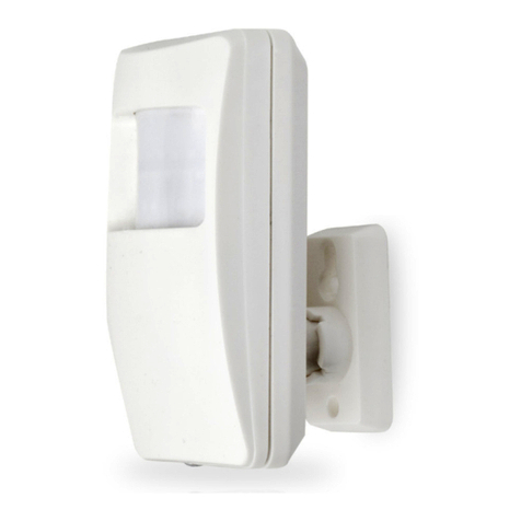
EWP3 Wireless motion detector 32***
EWD2 Wireless magnetic door contact/shock sensor/ood sensor 32***
EWD3 Wireless magnetic door contact/shock sensor/ood sensor 32***
EWK1**** Wireless keyfob with 4 buttons 5***
EWK2**** Wireless keyfob with 4 buttons 5***
EWS3 Wireless indoor siren 32***
EWK2A**** Wireless keyfob with 1 button 5***
EWS2 Wireless outdoor siren 32***
EKB3W Wireless LED keypad 4***
EWKB4 Wireless LED keypad 4***
EWKB5 Wireless touchpad 4***
EWF1 Wireless smoke detector 32***
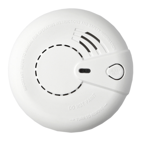
EWF1CO Wireless smoke and CO detector 32***
EWR2 Wireless signal repeater 4***
EWM1 Wireless power socket 32***
* - A mixed combination of EKB2 and EKB3 keypads is supported. The combination can consist of up to 4 keypads in total.
** - Only 1 of these modules can be connected at a time if the module slots are implemented in ESIM384 unit.
*** - A mixed combination of wireless devices is supported. The combination can consist of up to 32 wireless devices in total.
**** - A mixed combination of EWK1, EWK2 and EWK2A keyfobs is supported. The combination can consist of up to 5 keyfobs in total.
***** - EW2 creates 4 wireless zones, therefore the max. number of connectible EW2 devices is 16 if no keypad zones, no EPGM1 and no
virtual zones exist in the system’s conguration.
1.3. Default Parameters and Ways of Parameter Conguration
Main Settings
Parameter Default Value
Congurable by:
SMS EKB2
EKB3/
EKB3W/
EWKB4
Conguration
Software
User 1... 10 name N/A
User 1... 10 phone number N/A
User 1... 10 partition Partition 1
User 1...10 - call in case of alarm Enabled
Allow control from any phone number Disabled
SMS password 0000
SMS language Depends on the rmware
Partition 1 name PART1
Partition 2 name PART2
Partition 3 name PART3
Partition 4 name PART4

9
9
EN
ESIM384 Installation and Conguration Manual v1.1
Partition 1... 4 exit delay 15 seconds
GSM signal loss indication - delay 180 seconds
GSM signal loss indication – activate output N/A
Dual SIM management – SIM card switch Disabled
Dual SIM management – try to nd operator for a
maximum of 3 time (s)
Dual SIM management – send SMS/call via Currently in use SIM
Main Settings
Parameter Default Value
Congurable by:
SMS EKB2
EKB3/
EKB3W/
EWKB4
Conguration
Software
Passwords/Codes
Installer's code 1470
Duress code N/A
SGS code N/A
Passwords/codes format 4-digit
Prompt additionally for master code when cong-
uring via keypad/software Disabled
Master code 1111
Master code name N/A
Master code partition Partition 1, Partition 2, Partition 3, Parti-
tion 4
User code 2... 30 N/A
User code 2... 30 name N/A
User code 2... 30 partition Partition 1
Faults
Main power loss Enabled
Low battery Enabled
Battery dead or missing Enabled
Battery failed Enabled
Wired siren failed Enabled
RF jammer detected Enabled
Tamper alarm Enabled
Date/time not set Enabled
GSM connection failed Enabled
GSM antenna failed Enabled
Wireless antenna failed Enabled
Communication bus failed Enabled
Critical CO level Enabled
Wireless power socket fault Enabled
Wireless device low battery Enabled
Communication with MS failed Disabled
Notications
System armed – User 1... 10 Enabled
System armed – SMS delivery report Enabled
System disarmed – User 1... 10 Enabled
System disarmed – SMS delivery report Enabled
General alarm – User 1... 10 Enabled
General alarm – SMS delivery report Enabled
Main power loss/restore – User 1... 10 Enabled
Main power loss/restore – SMS delivery report Enabled
Battery failed – User 1... 10 Enabled
Battery failed – SMS delivery report Enabled
Battery dead or missing – User 1... 10 Enabled
Battery dead or missing – SMS delivery report Enabled
Low battery – User 1... 10 Enabled
Low battery – SMS delivery report Enabled
Siren fail/restore – User 1... 10 Disabled

10
10
EN ESIM384 Installation and Conguration Manual v1.1
Siren fail/restore – SMS delivery report Disabled
RF jammer detected – User 1... 10 Disabled
RF jammer detected – SMS delivery report Disabled
Date/time not set – User 1... 10 Disabled
Date/time not set – SMS delivery report Disabled
GSM connection failed – User 1... 10 Disabled
GSM connection failed – SMS delivery report Disabled
GSM/GPRS antenna fail/restore – User 1... 10 Disabled
GSM/GPRS antenna fail/restore – SMS delivery
report Disabled
Tamper alarm/restore – User 1... 10 Enabled
Tamper alarm/restore – SMS delivery report Enabled
Communication bus fail/restore – User 1... 10 Enabled
Communication bus fail/restore – SMS delivery
report Enabled
Temperature info – User 1... 10 Enabled
Temperature info – SMS delivery report Enabled
System started – User 1... 10 Enabled
System started – SMS delivery report Enabled
Periodical info – User 1... 10 Enabled
Periodical info – SMS delivery report Enabled
Wireless signal loss – User 1... 10 Enabled
Wireless signal loss – SMS delivery report Enabled
Unable to arm – User 1... 10 Enabled
Unable to arm – SMS delivery report Enabled
Zone bypass - User 1... 10 Enabled
Zone bypass – SMS delivery report Enabled
Critical CO level - User 1... 10 Enabled
Critical CO level – SMS delivery report Enabled
Wireless socket signal loss/restore - User 1... 10 Disabled
Wireless socket signal loss/restore – SMS delivery
report Disabled
Report/Control zone triggered - User 1... 10 Enabled
Report/Control zone triggered - SMS delivery
report Enabled
Incoming SMS forwarding - User 1... 10 Enabled
Incoming SMS forwarding - SMS delivery report Enabled
Wireless communication failed - User 1... 10 Disabled
Wireless communication failed - SMS delivery
report Disabled
Communication with MS failed - User 1... 10 Disabled
Communication with MS failed - SMS delivery
report Disabled
Send to all users simultaneously – all notications Disabled
Time Synchronization
Time synchronization Disabled
Phone number of the currently inserted SIM card N/A
Synchronization frequency 30 days
Event Log
Event log Enabled
Zones
Parameter Default Value
Congurable by:
SMS EKB2
EKB3/
EKB3W/
EWKB4
Conguration
Software
On Board
Z1... Z8 zone name Zone1... Zone8
Z1 type Delay
Z1... Z8 zone status Enabled
Z2... Z8 type Instant

11
11
EN
ESIM384 Installation and Conguration Manual v1.1
Z1... Z8 delay, ms 800 milliseconds
Z1... Z8 – Stay Disabled
Z1... Z8 – Force Disabled
Z1... Z8 Tamper name Tamper1... Tamper8
Delay-type zone – entry delay 15 seconds
Z1... Z8 partition Partition 1
Z1... Z8 – Shared Disabled
Z1... Z8 – audio track N/A
Z1... Z8 – alarm count to bypass 0
Cross-Zone/Intelli-Zone N/A
Conrmation Timeout 20 seconds
Tamper 1... 8 status Enabled
Z1... Z8 - zone connection type Type 1
Delay becomes Instant in STAY mode Disabled
Chime Enabled
ATZ mode Disabled
Arm-disarm by zone No1... No4 N/A
EPGM1 Module
Zone name Zone X
Zone status Enabled
Type Instant
Delay, ms 800 milliseconds
Stay Disabled
Force Disabled
Tamper name Tamper X
Delay-type zone – entry delay 15 seconds
Partition Partition 1
Shared Disabled
Audio track N/A
Alarm count to bypass 0
Cross-Zone/Intelli-Zone N/A
Conrmation Timeout 20 seconds
Tamper status Enabled
Zone connection type for all EPGM1 zones Type 1
Wireless Devices
Zone name Zone X
Zone status Enabled
Type Depends on the connected wireless device
model
Stay Disabled
Force Disabled
Tamper name Tamper X
Delay-type zone – entry delay 15 seconds
Partition Partition 1
Shared Disabled
Audio track N/A
Alarm count to bypass 0
Cross-Zone/Intelli-Zone N/A
Conrmation Timeout 20 seconds
Tamper status Enabled
Keypads
Zone name Zone X
Zone status Disabled
Type Instant
Stay Disabled
Force Disabled
Tamper name Tamper X
Delay-type zone – entry delay 15 seconds
Partition Partition 1
Shared Disabled
Audio track N/A

12
12
EN ESIM384 Installation and Conguration Manual v1.1
Alarm count to bypass 0
Cross-Zone/Intelli-Zone N/A
Conrmation Timeout 20 seconds
Tamper status Enabled
Virtual Zones
Zone name Zone X
Zone status Disabled
Type Instant
Force Disabled
Delay-type zone – entry delay 15 seconds
Partition Partition 1
Shared Disabled
Alarm count to bypass 0
Cross-Zone/Intelli-Zone N/A
Conrmation Timeout 20 seconds
Tamper status Enabled
PGM Outputs
Parameter Default Value
Congurable by:
SMS EKB2
EKB3/
EKB3W/
EWKB4
Conguration
Software
On Board
C1... C4 output name Controll1... Controll4
C1... C4 output state OFF
C1... C4 output status Enabled
Using module EPGM8 Disabled
EPGM1 Module
Output name ControllX
State OFF
Status Disabled
Wireless Devices
Output name ControllX
Type Depends on the connected wireless de-
vice model
State OFF
Status Disabled
MS Settings
Parameter Default Value
Congurable by:
SMS EKB2
EKB3/
EKB3W/
EWKB4
Conguration
Software
Management
MS mode Disabled
Main Account 9999
GSM and SMS – attempts 3
GSM and SMS – tel. number 1... 3 N/A
PSTN – treat PSTN call as user call Disable
PSTN – attempts 3
PSTN – tel. number 1... 3 N/A
CSD – attempts 3
CSD – tel. number 1... 5 N/A
Parallel data transfer via IP network Disabled
IP Server 1... 3 – IP attempts 3
IP Server 1... 3 – test period 180 seconds
IP Server 1... 3 – protocol UDP
IP Server 1...3 – account 9999
IP Server 1...3 – unit ID 0000
IP Server 1... 3 – communication protocol EGR100
IP Server 1... 3 – server IP 0.0.0.0
IP Server 1... 3 – server port 20000
IP Server 1... 3 – encryption key - status Disabled

13
13
EN
ESIM384 Installation and Conguration Manual v1.1
IP Server 1... 3 – encryption key 0000
Communication - primary IP Server 1 (GPRS)
Communication – backup 1... 5 N/A
Retry after delay N/A
Delay after last communication attempt 1200 seconds
SIA IP protocol settings - encryption Disabled
SIA IP protocol settings – encryption key 0000
SIA IP protocol settings – account prex N/A
SIA IP protocol settings – receiver number N/A
SIA IP protocol settings – use time stamp Enabled
SIA IP protocol settings – Contact ID ping Disabled
SIA IP protocol settings – data message Event: 1602, partition: 01, user/zone: 000
Data Messages
Burglary alarm/restore – code 130
Burglary alarm/restore – status Enabled
Main power loss/restore – code 301
Main power loss/restore – status Enabled
Armed/disarmed by user – code 401
Armed/disarmed by user – status Enabled
Test event – code 602
Test event – status Enabled
Battery failed – code 309
Battery failed – status Enabled
Battery dead or missing – code 311
Battery dead or missing – status Enabled
Tamper alarm/restore – code 144
Tamper alarm/restore – status Enabled
Instant Silent zone alarm/restore – code 146
Instant Silent zone alarm/restore – status Enabled
Kronos ping – code 602
Kronos ping – status Enabled
System started – code 900
System started – status Enabled
24H zone alarm/restore – code 133
24H zone alarm/restore – status Enabled
Fire zone alarm/restore – code 110
Fire zone alarm/restore – status Enabled
Low battery – code 302
Low battery – status Enabled
Temperature exceeded – code 158
Temperature exceeded – status Enabled
Temperature fallen – code 159
Temperature fallen – status Enabled
Wireless signal loss/restore – code 381
Wireless signal loss/restore – status Enabled
Disarmed by user (duress code) – code 121
Disarmed by user (duress code) – status Enabled
SGS code entered – code 463
SGS code entered – status Enabled
Armed by user (partial arm) – code 456
Armed by user (partial arm) – status Enabled
RF jammer detected - code 344
RF jammer detected - status Enabled
Siren fail/restore – code 321
Siren fail/restore – status Disabled
Date/time not set – code 626
Date/time not set – status Enabled
GSM connection failed – code 358
GSM connection failed – status Enabled
GSM/GPRS antenna fail/restore – code 359
GSM/GPRS antenna fail/restore – status Disabled
System shutdown – code 414
System shutdown – status Enabled
Communication bus fail/restore – code 330

14
14
EN ESIM384 Installation and Conguration Manual v1.1
Communication bus fail/restore – status Enabled
IP connection failed – code 360
IP connection failed – status Enabled
Zone bypass/Bypassed zone activation – code 570
Zone bypass/Bypassed zone activation – status Enabled
CO sensor lifetime exceeded -code 380
CO sensor lifetime exceeded -status Enabled
Critical CO level - code 162
Critical CO level - status Enabled
Report/Control zone triggered/restored – code 150
Report/Control zone triggered/restored – status Disabled
Armed/disarmed in STAY mode – code 441
Armed/disarmed in STAY mode – status Enabled
Conguration via remote connection started -
code 412
Conguration via remote connection started -
status Disabled
Silent/Panic zone alarm/restore - code 120
Silent/Panic zone alarm/restore - status Enabled
Armed/disarmed automatically - code 403
Armed/disarmed automatically - status Enabled
SMS sending limit reached - code 458
SMS sending limit reached - status Disabled
Communication with MS failed - code 354
Communication with MS failed - status Disabled
Control / Scheduler
Parameter Default Value
Congurable by:
SMS EKB2
EKB3/
EKB3W/
EWKB4
Conguration
Software
PGM output control 1... 16 Disabled
Scheduler 1... 16 Disabled
Additional conditions Disabled
Peripheral Devices
Parameter Default Value
Congurable by:
SMS EKB2
EKB3/
EKB3W/
EWKB4
Conguration
Software
Keypads
Keypad 1... 4 partition Partition 1
Show armed status in keypad Disabled
Keypad partition switch Disabled
EKB3 mode 2 partitions
Wireless keypads - partition Partition 1
Wireless keypads – backlight timeout 10 seconds
Wireless keypads – bell Disabled
Siren
EWS2 LED Enabled
Bell squawk Disabled
Activate siren if wireless device is lost Disabled
EWS3 re alarm LED Disabled
EWS3 alarm LED Disabled
Bell squawk enabled if arming in STAY mode Disabled
Temperature Sensors
Temperature sensor 1... 8 name N/A
Temperature sensor 1... 8 min. temperature 0
Temperature sensor 1... 8 max. temperature 0
Primary No.1
Secondary No.2
iButton Keys
iButton key name N/A

15
15
EN
ESIM384 Installation and Conguration Manual v1.1
iButton key partition Partition 1
Allow adding new iButton keys Disabled
System
Parameter Default Value
Congurable by:
SMS EKB2
EKB3/
EKB3W/
EWKB4
Conguration
Software
Management
Mains power loss delay 30 seconds
Mains power restore delay 120 seconds
Alarm duration 1 minute
Wireless channel Depends on rmware
Periodic test Every 1 day at 11:00
Wireless device lost timeout Grade 2
Arming is not allowed after 20 mins of wireless
communication loss Disabled
SMS notications - day limit 25
SMS notications - day limit status Enabled
SMS notications - month limit 400
SMS notications - month limit status Enabled
Microphone level 12
Speaker level 85
SMS forward settings - forward all received SMS Disabled
SMS forward settings - forward all received SMS
from unknown users Disabled
SMS forward settings -forward all received SMS
from registered users with wrong syntax or
wrong password
Disabled
SMS forward settings - forward all received SMS
from specied phone number (status) Disabled
SMS forward settings - forward all received SMS
from specied phone number (phone number) N/A
Service mode Disabled
Cloud Services
Cloud Services Disabled
Server address ss.eldes.lt
Port 8082
Ping period 180 seconds
Time zone N/A
Communication Via GPRS network
GPRS Settings
SIM1... SIM2 APN N/A
SIM1... SIM2 user name N/A
SIM1... SIM2 password N/A
DNS1 N/A
DNS2 N/A
LAN Settings
DHCP Disabled
LAN IP address 0.0.0.0
LAN net mask 0.0.0.0
Default gateway 0.0.0.0
Primary DNS server 0.0.0.0
Secondary DNS server 0.0.0.0

16
16
EN ESIM384 Installation and Conguration Manual v1.1
2.TECHNICAL SPECIFICATIONS
2.1. Electrical and Mechanical Characteristics
Electrical and Mechanical Characteristics
Power supply 16-24V 50/60 Hz ~1.5A max / 18-24V 1,5A max
Current consumption in idle state w/o external devices connected Up to 80mA
Recommended backup battery voltage, capacity 12V; 1,3-7Ah
Recommended backup battery type Lead-Acid
Backup battery charge current Up to 500mA
Backup battery charge duration Up to 30 hours for 7Ah battery
GSM modem frequency 850/900/1800/1900MHz
Cable type for GSM/GPRS antenna connection Shielded
Number of zones on-board 8 (ATZ mode: 16)
Nominal zone resistance 5,6k (ATZ Mode: 5,6k and 3,3k)
Number of PGM outputs on-board 4
On-board PGM output circuit
1 R OUT Open collector output.
Output is pulled to COM
when turned ON.
Maximum commuting on-board PGM output values (combined) 4 x 30V; 500mA
BELL: Siren output when activated Connected to COM
BELL: Maximum siren output current 1A
BELL: Maximum cable length for siren connection Up to 100m (328.08ft)
BELL: Cable type for siren connection Unshielded
AUX: Auxiliary equipment power supply voltage 13,8V DC
AUX: Maximum accumulative current of auxiliary equipment 1,1A
AUX: Maximum cable length for auxiliary equipment connection Up to 100m (328.08ft)
AUX: Cable type for auxiliary equipment connection Unshielded
BUZ: Maximum current of mini buzzer 150mA
BUZ: Power supply voltage of buzzer 12V DC
BUZ: Cable type for mini buzzer connection Unshielded
Supported temperature sensor model Maxim®/Dallas® DS18S20, DS18B20
Maximum supported number of temperature sensors 8
DATA: Maximum cable length for 1-Wire communication Up to 30m (98.43ft)
DATA: Cable type for 1-Wire communication Unshielded
Supported iButton key model Maxim®/Dallas® DS1990A
Maximum supported number of iButton keys 16
Maximum supported number of keypads 4 x EKB2 / EKB3
Y/G: Maximum cable length for RS485 communication Up to 100m (328.08ft)
Y/G: Cable type for RS485 communication Unshielded
MIC: Maximum cable length for microphone connection Up to 2m (6.56ft)
MIC: Cable type for microphone connection Unshielded
Wireless band ISM868
Wireless communication range Up to 3000m (9842.6ft) in open areas
Maximum supported number of wireless devices 32
Event log size 1024 events
Maximum supported number of zones 80
Maximum supported number of PGM outputs 48
Cable type for zone and PGM output connection Unshielded
Generated PSTN line values Voltage: 48V; current: 25mA; impedance: 270
Communications SMS, Voice calls, GPRS network, CSD, PSTN, Ethernet via ELAN3-ALARM
Supported protocols Ademco Contact ID, EGR100, Kronos, Cortex SMS, SIA IP
Dimensions 140x100x18mm (5.51x3.94x0.71in)
Operating temperature range -20...+55°C (-4... +131°F)
Humidity 0-90% RH @ 0... +40°C (0-90% RH @ +32... +104°F)
(non-condensing)

17
17
EN
ESIM384 Installation and Conguration Manual v1.1
2.2. Main Unit, LED Indicator and Connector Functionality
Main Unit Functionality
GSM MODEM GSM network 850/900/1800/1900MHz
modem
SIM CARD1 Primary SIM card slot / holder
SIM CARD2 Secondary SIM card slot / holder
DEF Pins for restoring default settings
USB Mini USB port
FUSE F1 2A fuse
W-LESS ANT Wireless antenna SMA type connector
MIC Microphone connector
GSM/GPRS ANT GSM/GPRS antenna SMA type connector
MODULES* Slots for EA1, EA2 or EPGM8 module
ANTW-LESS GSM/GPRS ANT
TIP
FUSE F1
RING
DEF
SIM CARD1
SIM CARD2
PRG
USB
AK U+
AK U-
C 2
C 3
C 3
C 4
C 4
C 1
S TA T
NE TW
2A
MODULES
MIC
OPENOPEN
BELL-
BELL+
G
Y
C2
AUX-
AUX+
AC /DC
AC /DC
Z1
C O M
Z2
Z3
C O M
Z4
DA T A
+5V
BU Z -
C1
BU Z +
C O M
C O M
C O M
Z6
Z7
Z8
Z5
GSM
MODEM
1
LED Functionality
NETW GSM network signal strength
C1 PGM output C1 status - ON/OFF
C2 PGM output C2 status - ON/OFF
C3 PGM output C3 status - ON/OFF
C4 PGM output C4 status - ON/OFF
STAT Micro-controller status
NETW indication GSM signal strength
OFF No GSM signal
Flashing every 3 sec. Poor
Flashing every 1 sec. Medium
Flashing several times per sec. Good
Steady ON Excellent
Connector Functionality
TIP* PSTN (landline) terminal
RING* PSTN (landline) terminal
DATA 1-Wire interface for iButton key and temperature sensor connection
+5V Temperature sensor power supply terminal (+5V)
BUZ- Buzzer negative terminal
BUZ+ Buzzer positive terminal
C1 - C4 PGM output terminals
Z1 - Z8 Security zone terminals
YRS485 interface CLOCK terminal (yellow wire)
GRS485 interface DATA terminal (green wire)
COM Common return terminal
BELL- Siren negative terminal (Commutated)
BELL+ Siren positive terminal (Constant voltage)
AUX- Negative power supply terminal for auxiliary equipment
AUX+ Positive power supply terminal for auxiliary equipment
AC/DC Main power supply terminals
AKU- Backup battery negative terminal
AKU+ Backup battery positive terminal
* - Optional, implementable on request in advance

18
18
EN ESIM384 Installation and Conguration Manual v1.1
2.3. Wiring Diagrams
2.3.1.General Wiring
BELL-
BELL+
G
Y
C2
AUX-
AUX+
AC /DC
AC /DC
Z1
C O M
Z2
Z3
C O M
Z4
+5V
BUZ-
C1
BUZ+
C O M
C O M
DATA
C O M
Z6
Z7
Z8
Z5
BUZ
SIREN/BELL
iButton®
key reader
Temperature sensor EKB2EKB3
EPGM1
Z1
Z2
Backup Battery
12V 1.3-7Ah
Metal cabinet
PE terminal
Relay
module
1A max.
Z4
Z3
Z5
Z6
Fuse 500mA
~230V 50/60Hz
~16-24V
AKU+
AKU-
5,6 kΩ
5,6 kΩ
Z7
Z8
5,6 kΩ
5,6 kΩ
5,6 kΩ
5,6 kΩ
5,6 kΩ
5,6 kΩ
1 2 3
4 5 6
7 8 9
*0 #
2
2.3.2. Zone Connection Types
Type 1 Example of 4-wire smoke detector wiring
Z1
COM
AUX+
+Vin
GND
C1
COM
NO
5,6 kΩ
3
8-Zone mode: Nor-
mally open contact
with 5,6K end-of-
line resistor.
ZCOM
NO
EOL 5.6K
ZCOM
NC
EOL 5.6K
ZCOM
NC
NC
5.6K
3.3K
ZCOM
NC
3.3K
EOL 5.6K
TAMPER
ZCOM
NC
3.3K
NC
5.6K
EOL 5.6K
TAMPER
Type 2 Example of magnetic door contact wiring
COM
NC
Magnet
COM
Z1
5,6 kΩ
ZCOM
NO
EOL 5.6K
ZCOM
NC
EOL 5.6K
ZCOM
NC
NC
5.6K
3.3K
ZCOM
NC
3.3K
EOL 5.6K
TAMPER
ZCOM
NC
3.3K
NC
5.6K
EOL 5.6K
TAMPER
8-Zone mode: Nor-
mally closed contact
with 5,6K end-of-
line resistor
4
NOTE: Based on the example given, in the event of an alarm, the smoke detector could be reset by turning OFF and ON the PGM output
C1. For more details, please refer to 18.4. Turning PGM Outputs ON and OFF.

19
19
EN
ESIM384 Installation and Conguration Manual v1.1
NOTE: The system does NOT support 2-wire smoke detectors.
Type 3 Example of motion detector wiring
Z1
COM
COM
AUX+
AUX-
+Vin
GND
NC
TAMP
5,6 kΩ 3,3 kΩ
ZCOM
NO
EOL 5.6K
ZCOM
NC
EOL 5.6K
ZCOM
NC
NC
5.6K
3.3K
ZCOM
NC
3.3K
EOL 5.6K
TAMPER
ZCOM
NC
3.3K
NC
5.6K
EOL 5.6K
TAMPER
5
8-Zone mode: Tamper
and 5,6K end-of-line
resistor and 3,3K
end-of-line resistor
with normally closed
contact.
Type 4 Example of magnetic door contact (Z1) and glass break sensor (Z9) wiring
AUX+
+Vin
AUX-
GND
COM
COM
NC
NC
COM
Z1
5,6 kΩ
3,3 kΩ
Magnet
ZCOM
NO
EOL 5.6K
ZCOM
NC
EOL 5.6K
ZCOM
NC
NC
5.6K
3.3K
ZCOM
NC
3.3K
EOL 5.6K
TAMPER
ZCOM
NC
3.3K
NC
5.6K
EOL 5.6K
TAMPER
6
ATZ mode: 5,6K
end-of-line resistor
and normally closed
contact with 3,3K
end-of-line resistor
and normally closed
contact
Type 5 Example of motion detector (Z1) and magnetic door contact (Z9) wiring
ZCOM
NO
EOL 5.6K
ZCOM
NC
EOL 5.6K
ZCOM
NC
NC
5.6K
3.3K
ZCOM
NC
3.3K
EOL 5.6K
TAMPER
ZCOM
NC
3.3K
NC
5.6K
EOL 5.6K
TAMPER
Z1
COM
COM
COM
AUX+
AUX-
+Vin
GND
NC
NC
TAMP
5,6 kΩ5,6 kΩ 3,3 kΩ
Magnet
ATZ mode: Tamper,
5,6K end-of-line
resistor, 5,6K
end-of-line resistor
with normally closed
contact and 3,3K
end-of-line resistor
with normally closed
contact.
7
See also 14.3. 8-Zone Mode and 14.4. ATZ (Advanced Technology Zone) Mode.

20
20
EN ESIM384 Installation and Conguration Manual v1.1
2.3.3. Siren
RED +
BLACK -
BELL-
BELL+
SIREN/BELL
1A max.
8Piezo siren
1 Connect positive siren wire (red) to BELL+ ter-
minal.
2 Connect negative siren wire (black) to BELL-
terminal.
+12V
GND
BELL
BELL-
COM
BELL+
SIREN/BELL
1A max.
9Self-contained siren
1 Connect negative GND siren wire to COM termi-
nal.
2 Controlling BELL siren wire must be connected
to BELL- terminal.
3 Connect positive +12V siren wire to BELL+ ter-
minal.
RED +
BLACK -
BELL-
BELL+
SIREN/BELL
1A max.
3,3kΩ 3,3kΩ
10 Siren status monitoring
NOTE: Siren status monitoring feature supervises
the resistance across BELL+ and BELL- terminals.
The resistance must be ranging from 1k through
3,3k, otherwise the system will indicate system
fault. In order to view the siren resistance value,
please refer to Diagnostic Management feature
available on ELDES Conguration software.
RED +
BLACK -
BELL-
BELL+
SIREN/BELL
1A max.
11 No siren status monitoring
If the siren status monitoring feature is not re-
quired, do not connect any resistor in parallel and
disable siren fault indication on the keypad (see 29.
INDICATION OF SYSTEM FAULTS).
See also 20. SIREN/BELL.
NOTE: BELL- is the commuted terminal intended for siren control.
NOTE: Siren status monitoring feature supervises the resistance across BELL+ and BELL- terminals. The resistance must be ranging from
1k through 3,3k, otherwise the system will indicate system fault. In order to view the siren resistance value, please refer to Diagnostic
Management feature available on ELDES Conguration software.
Table of contents
Other Eldes Security System manuals

Eldes
Eldes ESIM264 User manual

Eldes
Eldes ESIM364 User manual

Eldes
Eldes ESIM264 User manual
Eldes
Eldes ME1 User manual
Eldes
Eldes ESIM364 User manual
Eldes
Eldes ESIM4 User manual

Eldes
Eldes ESIM364 User manual
Eldes
Eldes PITBULL ALARM Instruction Manual

Eldes
Eldes EPIR User manual
Eldes
Eldes ESIM262 User manual
Popular Security System manuals by other brands
Giant Alarm System
Giant Alarm System JJ-MB-02-2 user manual
Federal Signal Corporation
Federal Signal Corporation CP-PB Series manual
LEGRAND
LEGRAND Tynetec REACH Quick installation guide

resideo
resideo Total Connect Box user manual
Wilo
Wilo Control DrainAlarm Installation and operating instructions
Minut
Minut MT-P2 manual
