Eldes ESIM264 User manual

GSM ALARM AND MANAGEMENT SYSTEM
GSM APSAUGOS IR VALDYMO SISTEMA · GSM СИСТЕМА ОХРАНЫ И УПРАВЛЕНИЯ
ELDES ALARM
ESIM264
LT EN RU

Copyright c“ELDES UAB”, 2010. All rights reserved
It is not allowed to copy and distribute information in this document or pass to a third party without advanced written authorization by“ELDES UAB”.
“ELSDES UAB”reserves the right to update or modify this document and/or related products without a warning. Hereby, ELDES UAB declares that this GSM
Alarm System ELDES ESIM264 is in compliance with the essential requirements and other relevant provisions of Directive 1999/5/EC. The declaration of
conformity may be consulted at www.eldes.lt/ce
Manuall v1.0
Safety instructions
Please read and follow these safety guidelines in order to maintain safety of operators and people around:
• Alarm system ESIM264 (later referenced as system or detector) has radio transceiver operating in GSM850/900/1800/1900
bands.
• Don’t use the system where it can be interfere with other devices and cause any potential danger.
• Don’t use the system with medical devices.
• Don’t use the system in hazardous environment.
• Don’t expose the system to high humidity, chemical environment or mechanical impacts.
• Don’t attempt to personally repair the system.
• System label is on the bottom side of the device.
System ESIM264 is a device mounted in limited access areas. Any system repairs must be done only by qualied, safety
aware personnel.
The system must be powered by main 16-24V 50Hz ~1.5A AC or 18-24V 1.5A DC power supply which must be appro-
ved by LST EN 60950-1 standard and be easily accessible.
Any additional devices linked to the system ESIM264 (computer, sensors, relays etc.) must be approved by LST EN 60950-1
standard.
External power supply must be reachable and can be connected to AC mains only
inside installation room with automatic 2-pole circuit breaker capable of disconnec-
ting circuit in the event of short circuit or over-current condition. Open circuit brea-
ker must have a gap between connections of more than 3mm.
Mains power and back-up battery must be disconnected before any installation or
tuning work starts. The system installation or maintenance must not be done during stormy conditions.
The system must be used only with approved back-up battery to avoid re or explosion hazards. Special care must be
taken connecting positive and negative battery terminals.
Backup battery must be connected via the connection which in the case of breaking would result in disconnection of one
of battery pole terminals.
The device is switched o by 2-pole circuit breaker and disconnecting back-up battery connector.
Fuse F1 type – Slow Blown 3A. Replacement fuses have to be exactly the same as indicated by the manufacturer.
If you use I security class computer for setting the parameters it must be connected to earth.
in order to avoid re or explosion hazards the system must be used only with approved back-up battery. Special care
must be taken when connecting positive and negative battery terminals.
The WEEE (Waste Electrical and Electronic Equipment) marking on this product (see right) or its documentation indicates that the pro-
duct must not be disposed of together with household waste. To prevent possible harm to human health and/or the environment, the
product must be disposed on in an approved and environmentally safe recycling process. For further information on how to dispose
of this product correctly, contact the system supplier, or the local authority responsible for waste disposal in your area.
Phase
AC 230V
50 Hz/DC 24V
USB cable
Null
PE
ESIM264

LT
Limited Liability
The buyer must agree that the system will re-
duce the risk of re, theft, burglary or other dan-
gers but does not guarantee against such events.
“ELDES UAB”will not take any responsibility re-
garding personal or property or revenue loss while
using the system.
“ELDES UAB” liability according to local laws
does not exceed value of the purchased system.
“ELDES UAB”is not aliated with any of the cellular
providers therefore is not responsible for the quali-
ty of cellular service.
Manufacturer Warranty
The system carries a 24-month warranty by the
manufacturer “ELDES UAB”. Warranty period starts
from the day the system has been purchased by
the end user. The warranty is valid only if the sys-
tem has been used as intended, following all gui-
delines listed in the manual and within specied
operating conditions. Receipt must be kept as a
proof of purchase date.
The warranty is voided if the system has been
exposed to mechanical impact, chemicals, high
humidity, uids, corrosive and hazardous environ-
ment or other force majeure factors.
Package content:
1. ELDES Alarm ESIM264 ......................................qty. 1
2. Microphone............................................................qty.1
3. GSM Antenna........................ ...............................qty. 1
4. Mini buzzer................... ........................................qty. 1
5. Battery connection wire ..................................qty. 1
6. ESIM264 User Manual........................................qty. 1
7. Resistors 5,6kOm.................................................qty. 6
8. Resistors 3,3kOm.................................................qty. 6
About User Manual
This document describes alarm security system
ESIM264 installation and operation. It is very im-
portant to read User Manual before start using the
system.
A quick start guide is located in rst two chapters.
Chapter 3 and 4 describe additional system capa-
bilities.
CONTENT
1 General Information
1.1 Function.................................. .....................................................................4
1.2 Operation Description.............................................................................4
1.3 Technical Specications..........................................................................5
1.4 Connector and LED functionality........................................................5
1.5 Connection Circuit....................................................................................6
1.6 System installation........................................................ ...........................7
2. System pre-operation and essential control commands
2.1 Radio signal strength...............................................................................8
2.2 Selecting device language
and verication of SMS central number ..........................................8
2.3 Password change............................................ ..........................................9
2.4 User numbers................................................ .............................................9
2.4.1 Saving or Changing numbers..................... ...............................9
2.4.2 Verication of saved numbers....................................................9
2.4.3 Deletion of saved numbers.........................................................9
2.5 Date and time settings............................................................................9
3. Additional system capabilities
3.1 Alarm zone inputs and controlled outputs ............. ....................10
3.1.1 Zone, controlled output and system settings. STATUS .10
3.1.2 Changing alarm texts and controlled outputs .................10
3.1.3 Enabling/disabling zones.........................................................11
3.1.4 Enter and Exit time-out conguration ................................11
3.2 iButton key ........................................................... ................................... 11
3.3 Managing Cx controlled outputs. Timer ....................................... 12
3.4 Siren conguration................................................................................12
3.5 External power supply control.......................... ...............................12
3.6 INFO on Status indication SMS messages
(signal strength, status, temperature)... ......................................... 13
3.7 Remote Microphone listening ......................................... ................13
3.8 Blocking incoming numbers ............................................................. 13
3.9 Alarm message due to temperature limit.......... ..........................14
3.10 SMS message delivery to multiple users ......................................14
3.11 SMS message informing about system arming/disarming ...14
3.12 Using Wireless Devices.........................................................................15
4. Appendix
4.1 Restoring default parameters............................................................16
4.2 Software„ELDES Conguration Tool“ .............................................16
4.3 Technical support..... ............................................................. ...............16
4.4 Shortlist of essential functions................................ .........................17

4
1. General Information
1.1 Functionality
ESIM264 – microcontroller based security system for houses, cottages, country homes, garages and other buildings, also capable
of managing electrical devices and appliances over cellular GSM network. It can be used as Intercom system.
The system can be used in the following applications:
• Property security
• Thermostat, heating and air-conditioner control, temperature monitoring
• Lighting, garden watering, water pump and other electrical equipment control via SMS messages
• Remote listening of what is happening in the secured property with microphone.
• Mains 230V power status with SMS message
1.2 Operation description
When system is armed via phone call, there is no time delay; the alarm system is activated immediately. Meanwhile the system has 15
second delay before activation, meant for leaving premises if iButton or keyboard is used.The time delay is user congurable parameter
(see chapter 3.1.4). Mini buzzer and/or light emitting diode will inform if delay time has been engaged. The security alarm system will not
get armed if any of the zones is active, which will be reported via SMS message.
All panel zones can be congured as Delay zones with 15 seconds activation delay which allows user to disarm the system using iButton
or keyboard.The user is notied about running delay with audible and LED signaling. The user must insert iButton, enter pin code on the
keyboard or make deactivating phone call before delay ends, otherwise the system will sound and report alarm. Activated alarm can be
disabled same way, using iButton, keyboard or a by a phone call.
All security system ESIM264 zones can be congured to work in any of the following modes:
• Follow – this type of zone doesn't react and cause an alarm if violated during Delay mode (delay time to enter security code and
disarm the system).
• Instant – this type of zone immediately cause an alarm if it is violated. Usually this type of zones is used for doors, windows and
other detectors.
• Delay – this type of zone doesn't react to violation for 15 seconds and this time is set to disarm system via keypad. Also this type of
zone are usually used to connect contacts of entry doors. When Delay zone isn't violated during arming process the system enters
into Stay mode.
• 24H – this type of zone is used to connect sensors which must be monitored all the time, even when system is disarmed. Mostly
these zones are used to connect tampers which detects when PIR or security panel box is opened.
• Fire – this type of zone is used to connect smoke detectors and monitors all the time even if the system is disarmed. Fire zone alarm
is pulse (with pauses).
• Silent – This zone works as 24H zone. The only dierent is that when it is violated the system doesn't turn on the siren.
• Arm-Disarm – With this zone security system can be armed/disarmed with a “low” level impulse which is not shorter than 3
seconds. This mode can be set only for one zone. No resistance is connected when using 6 zone connection type and the input
must be NO (normally open). If ATZ mode is enabled the impulse is transmitted through resistance. If Z2-Z6 zones are used, the im-
pulse should be transmitted through 5.6k resistance, if Z7-Z12 zones - the impulse should be transmitted through 3.3k resistance.
• STAY – this mode enables users to arm and disarm alarm system while staying inside the secured premises. If Delay zone is not
violated during the exit delay, the system will bypass all STAY zones. If any door or windows are opened without disarming the
system - it will cause an alarm. This mode is ussualy used at night.
Security system ELDES ESIM264 with additional module EWT1 may act as an access point for ELDES wireless devices: PIR sensors EWP1,
expansion modules EW1 and EW2, sirens and magnetic door contacts EWD1. ELDES ESIM264 can work with up to 16 wireless devices
which can be located up to 150m. from the central security system. For more information about wireless equipment please read wireless
devices manuals. For wireless connection it is used 868MHz non-licensed frequency.
ESIM264 has an interface port used to connect up to 4 keyboards. This function allows to install security systems to buildings which has se-
veral entries. If the system has several keypads, it can be armed and disarmed from any of installed keypads.This port is also used to connect
the expansion module EPGM1, which expands the number of input zones to additional 16 zones and programmable outputs – to additio-
nal 2 outputs. System has battery check function. This function checks the battery health and reports when battery needs to be replaced.
When systems sends the message about battery replacement, it is hardly recommended to replace backup battery. ESIM264 uses EEPROM
memory, so even at full power cuts system don't lose conguration settings. Security system ELDES ESIM264 transmits Contact ID protocol
messages.This feature allows to connect security system to Monitoring Stations. ESIM264 has a function which monitors the condition of the
siren. If the system loses connection with the siren, it will immediately cause an alarm and users will be notied about interruption.

MANUAL ELDES ESIM264 V1.0 5
EN
1.3 Technical Specications
Electrical and mechanical specications
Main power supply 16-24V 50 Hz ~1.5A max or 18-24V 1,5A max
Current in standby without external sensors and keypad Up to 80mA
Back-up Battery voltage, capacity 12V; 1,3-7Ah
Back-up Battery type lead-acid
Max Battery charge current 900mA
GSM modem frequency 850/900/1800/1900MHz
Number of Zones on Board 6 (12 ATZ mode)
Nominal input resistance 5,6kOm (ATZ mode: 5,6kOm and 3,3kOm
Number of Outputs on Board 4x500mA (12 optional)
Output C1-C4 circuit
Output max parameters Current - 100mA, voltage - 30V
Siren output when activated Connected to COM
Auxiliary equipment supply voltage 13,8V DC
Max accumulative current of auxiliary equipment and siren 1A max
+5V maximal current supply voltage of buzzer 150mA max
Supply voltage of buzzer 5VDC
Dimensions 140x100x18mm
Operating temperature range -20...+55ºC
Temperature sensor type DS18S20, DS18B20„IButton/MAXIM“
Supported amount of keyboards 4 EKB2 and 1 EKB1
Radio transmitter-receiver frequency * 866.1 Mhz – 869.5 MHz
Radio communication range* up to 30m in premises; up to 150m in open areas
Maximum number of wireless devices* 16
Events log 1000
Maximum supported number of Zones 44
Maximum supported number of Outputs 44
Communications Ademco Contact ID, SMS, Voice Calls
1.4 Connector and LED functionality
Open collector output. Output is
pulled to COM when enabled.
1 R OUT
BC817
LL4148
SIM
C4
C3 CARD
GSM
MODEM
SMA
ANTENNA
FUSE
3A
PWR
Z4
Z3
Z2
Z1
C1
C2
NETWORK
Z5
Z6
STATUS
AKU+
AKU-
COM
BELL-
BELL+
G
Y
C2
AUX-
AUX+
AC/DC
AC/DC
Z1
COM
Z2
Z3
COM
Z4
DATA
+5V
MIC-
MIC+
BUZ-
C1
BUZ+
COM
COM
Z6
Z5
USB
DEF
PRG MODULES
MODULES
Fig. No.1
Short explanation of the main units
GSM MODEM GSM network 850/900/1800/1900MHz modem
SIM CARD SIM card
DEF Connectors for restoring default settings
USB Mini USB connector
FUSE 3A fuse
ANTENNA SMA GSM antenna SMA type connector
MODULES Additional modules connectors
* used only in system ESIM264 with module EWT1

6
Connector functionality
Z1;Z2;Z3;Z4;Z5;Z6
ATZ režime:
Z1;Z2;Z3;Z4;Z5;Z6;
Z7;Z8;Z9;Z10;Z11;Z12
Protected zone inputs
COM Common return pin for all zones
DATA Ibutton key, keypad or temperature
sensor pin
+5V Temperature sensor supply voltage
(+5V)
MIC- Microphone negative input
MIC+ Micorphone positive input
BUZ- Audio signalling device (buzzer)
negative input
BUZ+ Audio signalling device (buzzer)
positive input
C1; C2; C3; C4 Controlled C1, C2, C3 and C4
outputs
BELL- Audio siren negative input
BELL+ Audio siren positive input
AUX- Negative 13.8V supply for auxiliary
equipment and siren
AUX+ Positive 13.8V supply for auxiliary
equipment and siren
AC/DC Main power supply positive input
G Communication green wire (for
keyboard ant etc.)
Y Communication yellow wire (for
keyboard ant etc.)
AKU- Back-up battery negative input
AKU+ Back-up battery positive input
1.5 Connection Circuit
COM
BELL-
BELL+
G
Y
C2
AUX-
AUX+
AC/DC
AC/DC
Z1
COM
Z2
Z3
COM
Z4
DATA
+5V
MIC-
MIC+
BUZ-
C1
BUZ+
COM
COM
Z6
Z5
MIC
BUZ
SIREN
iButton
key reader
5.6k
Z1
Z2
AKU
12V 1.3-7Ah
Metal box
PE contact
Relay
module
Z4
Z3
Z5
Z6
5.6k
5.6k
5.6k
5.6k
Fuse 500 mA
~230V 50Hz
~16-24V
AKU+
AKU-
Fig. No. 2 Fig. No. 3
DS1820
1 2 3
iButton key
DATA
+5V
COM
Temperature
sensor
TEMPERATURE SENSOR
CONNECTION
DALLAS
DS1820
12
GND DATA +5V
3
123
Light emitted diodes (LED) functionality
STATUS Indicates running microcontroller
PWR Power supply OK
Z6 zone Z6 activated (ATZ mode: Z6 and Z12)
Z5 zone Z5 activated (ATZ mode: Z5 and Z11)
Z4 zone Z4 activated (ATZ mode: Z4 and Z10)
Z3 zone Z3 activated (ATZ mode: Z3 and Z9)
Z2 zone Z2 activated (ATZ mode: Z2 and Z8)
Z1 zone Z1 activated (ATZ mode: Z1 and Z7)
C1 C1 controlled output ON
C2 C2 controlled output ON
NETWORK GSM network strength

MANUAL ELDES ESIM264 V1.0 7
EN
Ways to connect Alarm Zones
Mode No. 1 Mode No. 2 Mode No. 3 Mode No. 4 Mode No. 5
Normally open contact
with 5,6KΩ end of line
resistor
Normally closed con-
tact with 5,6KΩ end of
line resistor
Tamper and 5,6KΩ
end of line resistor
and 3,3KΩ end of line
resistor with normally
closed contact
ATZ Mode: 5,6KΩ end
of line resistor and nor-
mally closed contact
with 3,3KΩ end of line
resistor and normally
closed contact
ATZ Mode: Tamper,
5,6KΩ end of line
resistor, 5,6KΩ end of
line resistor with nor-
mally closed contact
and 3,3KΩ end of line
resistor with normally
closed contact.
1.6 System installation
The system can be installed only in a metal or non-ammable plastic box. When the metal box is used it is necessary to ground
the box using yellow/green color cable. For the connection of 230V transformer use 3x0.75 mm2 1 thread double isolated cable.
The primary circuit of the transformer must be connected through 0.5A fuse. 230V power supply cables cannot be grouped with
low voltage cable group. For the connection of power supply and output connectors use 1 thread 2x0.75 mm2 cable. For the
connection of input/output connectors use 0.50 mm2 1 thread cable.
1. Place SIM card in the holder but make sure that SIM card PIN code request is disabled (PIN code can be disabled by putting SIM
card into mobile phone and following proper menus). SIM card should not have any remaining SMS messages. Then connect
antenna.
2. Install audio signalling device close to iButton key reader in order to hear system engaging or disengaging time-out period.
Light emitting diode could be used instead of audio signalling device, or both. Enclosure ED1 is recommended for convenient
installation.
3. Connect the circuit as shown in Fig. No.3.
4. Connect back-up battery and main power supply (transformer). The system will start in less than a minute. Indicator PWR will
report external power supply status. Indicator STATUS should be blinking which indicates successful microcontroller opera-
tion.
The system can be used without iButton key, but it’s good to have it as emergency switch in case your mobile phone
is dead or missing. Also iButton key can be uses as main key to enable or disable system
To increase system reliability, it is recommended not to use prepaid SIM cards. The system would fail to send any mes-
sages upon depletion of prepaid account. Also it is recommended to disable call forwarding and voice mail.
It is worth to choose the same GSM cellular provider as most users use assuring fast and reli-able SMS message deli-
very and phone call connection.
Even though alarm system ESIM264 installation is not complicated, it is recommended to be performed by a person
with basic knowledge in electrical engineering and electronics to avoid any system damage.

8
2. System pre-operation and
essential control commands
VERY IMPORTANT!!!
Underscore symbol ‘_’ in this manual is used to represent space. When writing SMS messages, every underscore symbol should be
replaced by single space symbol. XXXX – means password. Don’t leave any space at the beginning and the end of the message.
To set ESIM264 system parameters easier and quicker you can use the computer, USB cable and conguration program ESIM264
Conguration Tool. You can read more in chapter 4.2.
The main conguration steps:
• Select device language (see more at chapter 2.2)
• Change default password to a new one (see more at chapter 2.3)
• Enter rst user„NR1“ (see more at chapter 2.4)
After completing these steps, you can freely and successfully make other congurations.
2.1 Signal strength
Connect external power supply and watch for“PWR”indicator to light
up. “NETWORK” will start blinking when system registers with cellular
network.
Try to choose GSM antenna location with best signal strength based
on blinking frequency.
2.2 Selecting device language and verication of SMS central number
The language in which the device communicates with the user can be chosen before changing factory default password. To chan-
ge the language in the system that is already congured reset default settings as described in 4.1 appendix.
Send SMS message with the required language code to the number of the SIM card inserted in ESIM264.
E.g., if you want to set the English language send the following SMS message: EN
30-60 seconds later you should get an SMS message: „English language conrmed.“ Go to chapter 2.2 upon reception of this
message. Otherwise check for network connection and call ESIM264 system from your mobile and wait until the system drops the
call. You should get an SMS message asking to change default password. Otherwise check for
network connection and change SMS central number.
SMS central number is saved in SIM card, therefore if SIM card has been used to send SMS messa-
ges with a mobile phone, then you don’t’ need to change SMS central number. Often SMS central
number is already saved in SIM card by cellular operator.
Central number can be entered by sending SMS message:
SMS central number is provided by cellular network provider.
XXXX_SMS_+37011111111
“NETWORK” indicator blinking Meaning
OFF No network connection
Every 3 sec Poor network connection
Every 1 sec Medium network connection
Several times a sec Good network connection
Solid ON Excellent network con-
nection
Table of possible languages
Language Code
lithuanian LT
english EN
russian RU
estonian EE
latvian LV
german DE

MANUAL ELDES ESIM264 V1.0 9
EN
2.3 Password change
All SMS commands start with a password, so please memorize it well. Manufacturer default password is four zeros 0000, which is
necessary to change. Manufacturer default password can be changed by sending SMS message to ESIM264:
To replace your password, send SMS message:
XXXX – any four digit number except four zeros. Non-numerical characters like dots, colons, spaces
are not allowed. YYYY – old system password.
2.4 User numbers
System ESIM264 allows to pre-program up to ve dierent mobile numbers which will have access to and controls the system.
Number NR1 is mandatory while others can be skipped. All numbers must be entered starting with international country code.
E.g. national code for Lithuania is 370, UK – 44. Numbers should be entered based on priority, since the system will try to contact
rst entered number and in case of failure will follow with second and so on.
2.4.1 Saving or Changing numbers
Send SMS message:
Ones should be replaced with user numbers. Numbers don’t have to be entered all or in sequential order right away.
2.4.2 Verication of saved numbers
Send SMS message:
The system will reply with all pre-programmed numbers.
2.4.3 Deletion of saved numbers
Pre-programmed numbers can be erased by sending SMS message with numbers to be erased.
The system will not allow erasing rst number NR1. It can only be changed.
2.5 Date and time settings
It is important to set correct date and time, so that the system can send reports at specied times. Date and time can be set by
sending following format SMS message:
Where MMMM – means year, mn – month, dd – day, hh – hour, mi – minutes
0000_PSW_XXXX
YYYY_PSW_XXXX
XXXX_HELPNR
XXXX_NR2:DEL_NR3:DEL_NR4:DEL_NR5:DEL
XXXX_MMMM.mn.dd_va:mi
XXXX_NR1:37011111111_NR2:37011111111_NR3:37011111111_NR4:37011111111_NR5:37011111111
ESIM 264
ESIM 264
0000 psw
1111
1111 2010
.09.09
15:30

10
3. Additional system capabilities
3.1 Alarm zone inputs and controlled outputs
Activated zone can work in 7 dierent modes: Follow, Instant, Delay, 24H, Fire, Silent or Arm-Disarm (see chapter 1.2).
To activate or deactive any of these modes you can only by using software„ELDES Conguration Tool“
3.1.1 System and Zone settings. STATUS
To see the default texts of activated zones and controlled output names as well as their current settings and status send the following
SMS message:
You will receive the answer by SMS messages. E. g.:
The rst SMS message: The system in ARMED/DISARMED. Z1:ON/OFF Z2:ON/OFF Z3:ON/OFF Z4:ON/OFF Z5:ON/OFF Z6:ON/OFF
C1:CONTROLLER1:ON/OFF C2:CONTROLLER2:ON/OFF
The second SMS message: Z1:door triggered; Z2:windows triggered; Z3:re triggered; Z4:motion1 triggered; Z5:motion2 triggered;
Z6:motion3 triggered;
ON- means that appropriate zone is activated, i. e., it will react in the case of alarm. OFF- it is deactivated.
If controlled output was enabled with timer (see chapter 3.3 for more details), STATUS command will report remaining time for control-
led output to stay ON or OFF.
3.1.2 Changing alarm texts and controlled output names
Manufacturer set the following alarm texts for the triggered zones and controlled output names: Z1-door triggered, Z2-windows trigge-
red, Z3-re triggered, Z4-motion1 triggered, Z5-motion2 triggered, Z6-motion3 triggered, C1-CONTROL1, C2-CONTROL2.
E. g. if in the case of alarm zone Z4 is triggered, the system will send SMS message with the following text: motion1 triggered
Alarm texts can be changed by sending the following SMS message:
E.G. XXXX_Z1:Door intrusion;Z2:Fire sensor triggered;
The texts can be changed all at once for all zones, for several zones or one by one. Text limitation for one zone is 24 characters. The space
equals one symbol. It is necessary to put a semicolon at the end of each new text. As semicolon is used for separating texts for dierent
zones, it cannot be used in the middle of alarm texts. Also, the texts cannot have the same names as
control commands. Controller names can be changed by sending the following SMS message:
Maximum controller name length is 10 characters. Controller names should not contain a semicolon at
the end. Zone names and controller names cannot be changed simultaneously.
XXXX_STATUS
XXXX_Z1:NewAlarmText;Z2:NewAlarmText;Z3:NewAlarmText;Z4:NewAlarmText;Z5:NewAlarmText;Z6:Ne
wAlarmText;
XXXX_C1:NewControllerName_C2:NewControllerName
ESIM 264
1111 C1:
pump
In the system of ESIM264 with module EWT1 you can receive information about up to 32 additional zones inputs and/or
up to 32 additional controlled outputs (it depends on how many wireless devices is added to the security system). In this
case system will send a reply by SMS messages, in each of them placing information about 4 active zones inputs or/and
controlled outputs (you can receive up to 16 additional SMS messages).
Maximum supported number of zones is 44 and outputs – 44.

MANUAL ELDES ESIM264 V1.0 11
EN
XXXX_IBPROG:ON
XXXX_IBPROG:OFF
XXXX_RESETIB
XXXX_Z1:ON;Z2:ON;Z3:ON;Z4:ON;Z5:ON;Z6:ON;
XXXX_Z1:OFF;Z2:OFF;Z3:OFF;Z4:OFF;Z5:OFF;Z6:OFF;
XXXX_INOUT:SSI:SSO
ESIM 264
1111 Z1:
ON
ESIM 264
1111 INO
UT:20:30
3.1.3 Enabling/disabling zones
Enabling Zone
Any zone can be enabled by sending the following SMS message:
Disabling Zone
Any zone can be disabled by sending the following SMS message:
The zones can be enabled/disabled together or separately one by one.
3.1.4 Enter and Exit time-out conguration
Manufacturer set 15 sec. delay time to leave the premises when security system is armed by keyboard or iButton.This parameter can be
adjusted by SMS text message or conguration tool. It is common parameter to the whole system.
The delay time is used for entering security code or placing iButton into the reader when disarming security system. Manufacturer set 15
sec. delay time which can be separately adjusted for any Delay zone. This function is useful when there are several entrances and need
to set dierent delay times in dierent zones. Z1 zone time can be also adjusted by SMS text message.
Time-out period can be congured by SMS message:
Where SSI – Z1 Delay zone entry time-out after activation in seconds. SSO – exit time-out after activation.
There is no time-out if period is set to 0.
3.2 iButton keys
First iButton key can be associated with the system just by touching it to the reader without the need to send any SMS
message. The system will beep twice informing about successful iButton key association and button will be saved into
non-volatile system memory.
Other iButton keys can be associated by entering special mode via SMS message:
It’s unique code will be recorded by the system. Again successful operation will be notied by double beep. The system allows to
associate and save up to ve iButton key.
E.g.The system will save and record every new button until fth button has been recorded. When all buttons have been associated
and recorded, it’s necessary to send SMS message:
This SMS command will block adding new buttons. Failing to send this SMS message, the system will not accept and respond to
iButton key. The iButton key can be erased one a at time or all at once by SMS:
This SMS command will erase all recorded buttons, and new buttons can be added as described above.

12
3.3 Managing Cx Controller. Timer
Alarm system ESIM264 has 4 open-collector controlled outputs C1, C2, C3 and C4. They can be used to control various electrical devices
such as electric pumps, heating, lighting, etc. When outputs are enabled, it corresponds to output pins being pulled to ground (GND).
Enabling output:
Disabling ouput:
Set controlled output names can be used instead of C1,C2, C3 or C4.
Timer
Alarm system ESIM264 has internal timer clock. This feature allows any controlled output to be switched on or o for a specied time
period. The following SMS command should be sent:
ON – output enabled. OFF – disabled; vv – hours, valid values [00-24] mm – minutes, valid values [00-60]
ss - seconds, valid values [00-60]. It is not allowed to have all values equal zeros.
3.4 Siren conguration
Manufacturer default conguration for Siren alarm is 1 minute. The user can change this period or completely disable the siren. This
can be done via SMS:
T can have values [0 – 5]: 0 – Siren disabled, 1 – 1 minute, 2 – 2 minutes, etc.
Maximum period allowed is 5 minutes.
Siren period can be inquired by SMS:
System will send siren settings.
3.5 External power supply control
The system ESIM264 will report every time mains 230V power supply fails or recovers. In some remote places where mains power
supply is unreliable, the system can be congured to ignore these changes. Send SMS:
Or it can be enabled by SMS message:
XXXX_SIREN:T
XXXX_SIREN
ESIM 264
1111
SIREN:5
XXXX_M:OFF
XXXX_M:ON
ESIM 264
1111 M:
OFF
XXXX_C1:ON/OFF:VV.MM.SS
XXXX_C1:ON
XXXX_C1:OFF
ESIM 264
1111 C2:
ON
ESIM 264
1111 C1:
ON:00.01.
23

MANUAL ELDES ESIM264 V1.0 13
EN
3.6 INFO on Status indication SMS messages (signal strength, status, temperature)
Security system ESIM264 can be inquired at any time about its status, signal strength, zone status. At the same time system can be
tested. If SMS response message is received, means system is functioning properly. This is also useful for users with prepaid SIM cards. It
can be checked whether SIM card has enough remaining balance for sending SMS. Send SMS message:
The response SMS message will be received, e.g.2009.01.07 11:15 System armed/disarmed Signal Strength Fair. External power supply
OK. Temperature 20oC. Z1:OK/ALARM Z2:OK/ALARM Z3:OK/ALARM Z4:OK/ALARM Z5:OK/ALARM Z6:OK/ALARM
Where OK – if zone has not been activated, ALARM – if been activated
By default, this status SMS message will be sent daily at 11:00 in the morning. These parameters can be
congured with SMS message:
PP – message period in days, valid values [00 – 10]; VV - time when message is sent, valid values
[00 – 23]
If PP value is 0, and VV in the range of [1-23], then periodic status messages will be sent multiple
times per day, with period being specied as VV time.
E.g. XXXX_INFO:0.2, means that status message will be sent every 2 hours.
To disable periodic status messages, send SMS:
The status message INFO will not be sent until enabling or restoring default parameters.
3.7 Remote Microphone listening
To be able to listen what is going on in remote house can be done in two dierent ways:
1. When alarm has been activated, the system will ring pre-programmed numbers and user can answer the call. Remote
microphone will be enabled for listening.
2. By sending SMS message
The system will ring the sender of former SMS, and upon answering the call, user can listen to any sounds in the building. The
phone call must be answered within 20 seconds otherwise the system will stop trying and return to previous state.
3.8 Blocking unknown incoming numbers
By default ESIM264 can be controlled from any of the pre-programmed numbers NR1 .. NR5. But user can access the system and
control parameters from any number as long as password is know.
To enable this feature, send SMS message:
To disable this feature, send SMS message:
XXXX_INFO
XXXX_INFO:PP.VV
XXXX_INFO:00.00
ESIM 264
1111 INFO
:0.2
XXXX_MIC
ESIM 264
1111 STR
:ON
XXXX_STR:ON
XXXX_STR:OFF

14
XXXX_TEMP
XXXX_TEMP:0:0
XXXX_MASTER:OFF
XXXX_MASTER:ON
XXXX_SMSALL:ON
XXXX_SMSALL:OFF
3.9 Receiving alarm message due to temperature deviation
The system ESIM264 informs the user by SMS message in the case if temperature deviation from the set values. In order to use this
function it is necessary to connect temperature sensor and set the parameters accordingly. Examples of usage: temperature control for
greenhouses, houses, aquariums, server premises, refrigerators etc.over GSM network.
Manufacturer set this function o. To turn the system on send the following SMS message:
min – temperature in oC, it can have values [-55...+125]
max – temperature in oC, can have values [-55...+125].
If the controlled temperature drops below min value by one degree, the user will receive SMS message with the temperature at that
time. If the controlled temperature rises above max value by one degree, the user will receive SMS message with the temperature at
that time.
E.g. XXXX_TEMP:16:20 means that SMS message will be sent if the temperature drops below 16oC or rises above 20oC.
XXXX_TEMP:-10:-1 means that SMS message will be sent if the temperature drops bellows -10oC or rises above -1oC
To see temperature settings send the following SMS message:
To turn o temperature control, send the following SMS message:
If the value received by the system is two zeros, it will not react to temperature change. However, if the
sensor is connected, temperature information will be sent together with INFO message, as described
in section 3.6.
3.10 SMS message delivery to multiple users
Upon activated alarm, SMS messages are repeatedly sent until rst successful delivery to one of the users. System starts with NR1,
and if delivery fails, follows with NR2, etc. It is also possible that SMS message will be sent to all recorded users.
To enable this function, send SMS message:
To disable this function, send SMS message:
3.11 SMS message informing about system arming/disarming
By default the user NR1 will receive a short message every time system is armed or disarmed. To disable this function, send SMS
message:
To re-enable this function, send SMS message
XXXX_TEMP:min:max
ESIM 264
1111 TEMP
:16:20
ESIM 264
1111
MASTER:ON

MANUAL ELDES ESIM264 V1.0 15
EN
3.12 Using Wireless Devices
Security system ESIM264 with module EWT1 can be expanded by connecting additional wireless ELDES devices:
• PIR sensors EWP1 (motion detectors). It allows to expand secured territory up to 16 additional security zones;
• expansion modules EW1 with 2 inputs and 2 programmable outputs. It is used for attaching more devices (various detectors,
sirens) to the security system.
• expansion modules EW2 with 4 inputs and 6 programmable outputs. It is used for attaching more devices (various detectors,
sirens) to the security system.
• wireless sirens;
• wireless magnetic door/window sensors EWD1;
It is possible to connect up to 16 wireless devices to the central security system at a time. Maximum distance for wireless connection is
150 meters (in open areas). For more information please check user manuals of these devices.

16
4. Appendix
4.1 Restoring Default Parameters
To restore default parameters:
1. Disconnect main power supply and back-up battery.
2. short circuit (connect) connectors DEF
3. connect power supply for several seconds
4. disconnect power supply
5. disconnect connectors DEF
4.2 Software„ELDES Conguration Tool“
To congure the system quicker and easier as well as use more system capabilities use conguration program„ELDES Congura-
tion Tool” which can be downloaded from our website www.eldes.lt
Before connecting USB cable to the computer read ELDES CongTool user guide available in the program chapter HELP.
4.3 Technical support
Indication Possible reason
PWR indicator OFF · No external power supply
· Circuit not properly connected
· Blown fuse
NETWORK indicator OFF or not blinking · missing SIM card
· PIN code hasn’t been disabled
· SIM card not active
· Disconnected antenna
· Network signal too weak
· Problems with cellular network provider
STATUS indicator solid ON or solid OFF · microcontroller program didn’t start properly due to electrical mains noise or
static discharge
System does not send any SMS messages and/or does
not ring
· SIM card account depleted
· Incorrect SIM central number
· No network signal
· User number is not programmed in (or disabled access from unknown
numbers)
· SIM card has been changed without disconnected external power supply or
back-up battery
Received SMS message“Incorrect Format” · Wrong syntax
· extra space symbol could be space left in SMS message
Missing temperature reading in“INFO”message · temperature sensor not connected
· Temperature sensor broken
· Connecting wires too long
24-hour or re modes don’t work · Specic zone must be enabled by ON command
No sound while listening to remote microphone · microphone not connected
· Microphone connection incorrect
Failing to record IButton key · Failed contact in button reader
· Reader connection incorrect
· IButton key record mode not enabled
· Trying to save more than ve buttons
· Connecting wires too long

MANUAL ELDES ESIM264 V1.0 17
EN
Failed to activate/deactivate system with iButton key. · Failed contact in button reader
· Reader connection incorrect
· IButton key record mode not enabled
· Button not been saved in system memory
Siren starts without system alarm detection · Enabled Fire or 24-our mode for specic zone
Buzzer SIREN silent · Siren connection has polarity mixed up
With detection of active zone and starting siren,
the system could not be disabled from rst short
phone call. It takes few phone calls to disable alarm
system.
· One of the saved numbers NR1-NR5 has voice mail activated.
If your problem could not be xed by the self-guide above, please contact your distributor or manufacturer tech support by email
[email protected] More up to date information about your device and other products can be found at the manufacturer’s website
www.eldes.lt
4.4 Shortlist of essential functions
Phone call IButton button
Arming Ring the system. If phone call gets
dropped after 3 rings, the system in armed.
Zones shouldn’t be activated during
phone call.
Place your button to the reader. Audio
signalling device will start beeping, inform-
ing to leave the premises. Zones shouldn’t
be activated when placing button to the
reader.
Disarming Ring the system. If phone call is dropped
after one ring, then the system alarm is
disarmed
Place button into the reader. Buzzer should
stop beeping.
To nd out system status, temperature,
230V mains status, signal strength
Send SMS message: XXXX_INFO
To nd out programmed user numbers Send SMS message: XXXX_HELPNR
To nd out zone and output controller
names and their status
Send SMS message: XXXX_STATUS
When IButton key has been lost Erase all programmed IButton keys by sending SMS message: XXXX_RESETIB

Copyright ©“ELDES UAB”, 2010. Visos teisės saugomos
Draudžiama kopijuoti, kaupti ar perduoti tretiesiems asmenims, šiame dokumente esančią informaciją, ar bet kokią dokumento dalį be išankstinio raštiško
“ELDES UAB”sutikimo. “ELDES UAB”pasilieka teisę be išankstinio įspėjimo tobulinti ar keisti bet kuriuos dokumente paminėtus gaminius, taip pat patį
dokumentą. Šiuo ELDES UAB deklaruoja, kad ši GSM apsaugos sistema ESIM264 atitinka esminius reikalavimus ir kitas 1999/5/EC Direktyvos nuostatas. Jos
atitikties deklaraciją galima rasti šiame tinklalapyje: www.eldes.lt/ce
Vartotojo vadovas v1.0
Saugos informacija
Kad užtikrinti jūsų ir aplinkinių saugumą prašome perskaityti šias taisykles, bei laikytis visų vartotojo vadove esančių montavimo
instrukcijų ir nurodymų:
• Apsaugos sistema ESIM264 (toliau – sistema) turi įmontuotą radijo siųstuvą, veikiantį GSM850/900/1800/1900 tinkluose.
• Nenaudokite sistemos ten, kur ji gali sukelti trikdžius.
• Nemontuokite sistemos prie medicininės aparatūros ar prietaisų, jei jie to reikalauja.
• Nenaudokite sistemos sprogiose vietose.
• Sistema nėra atspari drėgmei, cheminei aplinkai, bei mechaniniams poveikiams.
• Neremontuokite sistemos patys.
• Sistemos ženklinimo lipdukas yra apatinėje įrenginio plokštės pusėje.
Sistema yra ribotos prieigos zonos įrenginys. Sistemą montuoti ir remontuoti gali tik asmuo turintis žinių apie bendruo-
sius saugos reikalavimus ir pakankamą tam darbui kvalikaciją.
Sistema turi būti maitinama iš 16-24V 50Hz ~1.5A kintamosios srovės arba 18-24V 1.5A nuolatinės srovės maitinimo
šaltinio ir rezervinio maitinimo šaltinio – 12V 1,3-7Ah baterijos. Naudojami maitinimo šaltiniai privalo tenkinti LST EN
60950-1 standarto reikalavimus.
Kiekvienas prie sistemos prijungtas susietasis įrenginys (kompiuteris, jutikliai, rėlės ir pan.) privalo tenkinti LSTEN 60950-1
standarto reikalavimus.
Sistemos išorinis maitinimo šaltinis turi būti lengvai pasiekiamas ir gali būti prijung-
tas tik prie kintamosios srovės tinklo, instaliavimo patalpoje, turinčio visiškai grandi-
nę nutraukiančią automatinę apsaugą. Automatinė apsauga turi suveikti nuo trum-
pojo jungimo ar viršsrovių ir turėti dvipolį atjungimo įtaisą, kuris nutraukia grandinę.
Tarp nutrauktos grandinės kontaktų turi būti ne mažesnis kaip 3mm tarpelis.
Prieš pradedant montavimo ar derinimo darbus privaloma atjungti išorinį įrenginio maitinimą ir rezervinę bateriją. Drau-
džiama liesti kintamosios srovės elektros tinklo grandinės dalis kol jose yra įtampa.
Draudžiama liesti įrenginį ar atlikti derinimo darbus žaibuojant.
Baterija privalo būti prijungta per jungtį, kurią nutraukus, būtų atjungtas vienas baterijos polių.
Įrenginio pilnas išjungimas atliekamas išjungus išorinį elektros maitinimo šaltinio dvipolį atjungimo įtaisą ir atjungus ba-
terijos jungtį.
Saugiklio FUSE tipas Slow blown 3A. Perdegusio saugiklio negalima keisti kitokiu tipu nei nustatyta gamintojo.
Nenaudoti netinkamo tipo baterijos nes galimas gaisras ar sprogimas. Draudžiama sumaišyti vietomis ar užtrumpinti
baterijos polius.
Jei parametrų nustatymui yra naudojamas I saugumo klasės kompiuteris, jis privalo būti įžemintas.
Pagal WEEE direktyvą, perbrauktos šiukšlių dėžės su ratais ženklas reiškia, kad nebetinkamą naudoti gaminį Europos Sąjungoje reikia
atiduoti perdirbti atskirai nuo kitų šiukšlių.
Phase
AC 230V
50 Hz/DC 24V
USB cable
Null
PE
ESIM264

LT
Atsakomybės ribojimas
Pirkėjas sutinka, kad sistema sumažina gaisro,
plėšimo, vagystės ar kitą riziką, tačiau tai nėra drau-
dimas ar garantija, kad paminėti veiksniai neįvyks,
bei nebus asmenų sužeidimų, ar turto praradimo,
ar sunaikinimo atvejų.
“ELDES UAB”neprisiima jokios atsakomybės už
tiesioginę ar netiesioginę žalą ar nuostolius, taip
pat negautas pajamas, naudojantis sistema.“ELDES
UAB”atsakomybė, kiek tai leidžia galiojantys įstaty-
mai, neviršija produkto įsigijimo kainos.
Korinio ryšio paslaugas teikiantys GSM opera-
toriai nėra susiję su “ELDES UAB” bendrove. Todėl
bendrovė neprisiima jokios atsakomybės už tinklo
paslaugas, jo aprėptį bei funkcionavimą.
Garantinis laikotarpis
“ELDES UAB” suteikia įsigytam produktui 24
mėn. garantiją.
Garantinis laikotarpis pradedamas skaičiuo-
ti nuo produkto pardavimo pirmam galutiniam
vartotojui datos. Garantija taikoma tik jei sistema
buvo naudota pagal paskirtį, laikantis visų vartoto-
jo vadovo instrukcijų, bei techninėje specikacijoje
nustatytų sąlygų ir maksimalių leistinų reikšmių.
Pardavimo data laikoma čekio, sąskaitos ar kito
pardavimo dokumento data. Garantija taikoma tik
kartu su paminėtais dokumentais pateikus užpildy-
tą garantinį taloną.
Garantija netaikoma jei sistema buvo paveikta
mechaniškai, cheminių medžiagų, drėgmės, koro-
zijos, skysčių, ekstremalių aplinkos veiksnių ar kito-
kių force majeure aplinkybių.
Pakuotės sudėtis:
1. ELDES Alarm ESIM264 ........................................1vnt
2. Mikrofonas...............................................................1vnt
3. GSM Antena............................................................1vnt
4. Garsinis signalizatorius (mini sirena)..............1vnt
5. Akumuliatoriaus prijungimo laidas................1vnt
6. ESIM264 vartotojo vadovas...............................1vnt
7. Rezistoriai 5,6kOm................................................6vnt
8. Rezistoriai 3,3kOm................................................6vnt
TURINYS
1. Bendroji informacija
1.1 Paskirtis......................................................................................................20
1.2 Veikimo aprašymas................................................................................20
1.3 Techninė specikacija...........................................................................21
1.4 Kontaktų ir LED indikatorių paskirtis...............................................21
1.5 Pajungimo schema................................................................................ 22
1.6 Sistemos instaliavimas.................... .....................................................23
2. Sistemos paruošimas darbui ir pagrindinės valdymo komandos
2.1 Ryšio stiprumas.......................................................................................24
2.2 Įrenginio kalbos pasirinkimas
bei SMS centro numerio patikrinimas............................................24
2.3 Slaptažodis ir jo keitimas.....................................................................25
2.4 Vartotojo numeriai..................... ...........................................................25
2.4.1 Užprogramavimas arba keitimas................. ..........................25
2.4.2 Užprogramuotų numerių užklausa....................................... 25
2.4.3 Užprogramuotų numerių trynimas.......................................25
2.5 Laiko ir datos nustatymas............................ ....................................... 25
3. Papildomos sistemos galimybės
3.1 Apsaugos zonos ir valdikliai............................................................... 26
3.1.1 Sistemos, zonų ir valdiklių būsenos
nustatymai. STATUS................................................................26
3.1.2 Aliarmo tekstų ir valdiklių pavadinimų keitimas ...... ..26
3.1.3 Zonų įjungimas/išjungimas.................................................27
3.1.4 Gaisro zona....................................................................... ........27
3.1.5 24valandų zona................................................................. .....27
3.1.6 Įėjimo ir išėjimo iš patalpos trukmės kongūravimas....27
3.2 iButton raktai...........................................................................................27
3.3 Valdiklių Cx valdymas. Laikmatis .....................................................28
3.4 Sirenos nustatymai................................................................................28
3.5 Išorinio maitinimo kontrolė................................................................28
3.6 Informacinės SMS žinutės INFO
(ryšio stiprumas, būsena, temperatūra).........................................29
3.7 Patalpų praklausymas mikrofonu................ .................................... 29
3.8 Svetimų numerių uždraudimas ........................................................29
3.9 Aliarmo žinutės gavimas dėl temperatūros nuokrypio............30
3.10 SMS žinučių pristatymas visiems vartotojams . ..........................30
3.11 SMS žinutė informuojanti apie
apsaugos įjungimą ar išjungimą.......................................................30
3.12 Belaidžių įrenginių panaudojimas........................... ........................31
4. Priedas
4.1 Gamyklinių parametrų atstatymas........................... .......................31
4.2 Kongūravimo programa ELDES Conguration Tool ...............32
4.3 Techninė pagalba..... .............................................................................32
4.4 Pagrindinių funkcijų atmintinė .........................................................32
Apie vartotojo vadovą. Greitas startas.
Šis dokumentas aprašo apie apsaugos sistemą ESIM264, jos veikimą, bei instaliavimą. Prieš pradedant naudotis sistema būtina
perskaityti vartotojo vadovą.
Pirmame ir antrame skyriuje aprašyta informacija reikalinga greitam startui. Trečiame ir ketvirtame – apie sistemos papildomas
galimybes.

20
1. Bendroji informacija
1.1 Paskirtis
ESIM264 – tai mikroprocesorinis prietaisas, skirtas gyvenamųjų patalpų, sodo namelių, vasarnamių, garažų, taip pat kitų patalpų
apsaugai ir elektrinių prietaisų valdymui ar kontrolei per GSM tinklą. Taip pat galima naudoti kaip pasikalbėjimo įrenginį.
Sistemos pritaikymo pavyzdžiai:
• Patalpų apsauga
• Aliarmo mygtuko prijungimas
• Temperatūros matavimas ir kontrolė patalpoms arba šildymo sistemoms
• Apšvietimo, šildymo, vėdinimo, laistymo, siurblių įjungimo ir kt. valdymas SMS žinute
• Patalpos praklausymas mikrofonu
• Informavimas SMS žinute apie 230V elektros tinklo dingimą ir atsiradimą
• Pasikalbėjimo įrenginys per GSM tinklą
1.2 Veikimo aprašymas
Suveikus pirmajai zonai, yra nustatytas gamintojo 15 sekundžių užlaikymas, kurio metu nereaguojama į visų užprogramuotų zonų suvei-
kimą, o vartotojas įspėjamas garsiniu ar/ir šviesos signalu apie laiko skaičiavimo pradžią tam, kad galėtų išjungti apsaugą iButton raktu,
klaviatūra ar kitomis priemonėmis. Užlaikymo kongūravimas aprašytas 3.1.4 punkte. Jei išsekus šiam laiko tarpui iButton raktas nebūna
įstatytas į skaitytuvą arba vartotojas nepaskambina sistemai iki jos skambučio automatinio atmetimo - sistema iš karto pereina į aliarmo
būseną, kuri išjungiama tik įstatant iButton raktą į skaitytuvą arba paskambinant sistemai.
Visos apsaugos sistemos ELDES ESIM264 zonos gali būti sukongūruotos veikti bet kuriuo iš numatytų veikimo būdų:
•Follow – sistema nereaguoja į šios zonos suveikimus, vykstančius esant Delay režimui (uždelsime, skirtame suvesti apsaugos nuė-
mimo kodą). Jei Delay užlaikymas nebus panaudotas, suveikus zonai, sistema įjungs aliarmą iškarto.
•Instant – sistema, esant zonos suveikimui, iškart įjungia aliarmą. Šio tipo zonos dažniausiai naudojamos durų, langų ir perimetro
zonose.
• Delay – sistema nereaguoja į zonos suveikimus tam tikrą laiko tarpą, kuris skirtas klaviatūra suvesti apsaugos nuėmimo kodui. Šio
tipo zonos paprastai naudojamos magnetiniams įėjimo durų kontaktams. Kai sistema priduodama apsaugai ir zona Delay nebuvo
suveikusi (nebuvo išeita iš patalpų), sistema pereina į nakties (Stay) režimą.
• 24H – šio tipo zonose patartina prijungti įrenginius, kurie turi būti stebimi visuomet, net ir esant išjungtai apsaugos sistemai. Pavyz-
džiui, šios zonos naudojamos stebėti tamperius, kurie detektuoja kai atidaromi PIR daviklio ar apsaugos centralės dėžės korpusai.
• Fire – zonos naudojamos dūmų jutikliams prijungti. Šio tipo zona yra nuolatos veikianti, todėl esant zonos suveikimui sistema
įjungia aliarmą ir nesant aktyvuotai signalizacijai. Fire zonos sirenos aliarmo signalas yra pulsinis (su pertraukomis).
• Silent – Ši zona veikia kaip 24H zona. Nuo 24H zonos skiriasi tuo, kad jai suveikus, sistema neįjungia sirenos.
• Arm-Disarm – Naudojant šia zona galima įjungti/išjungti apsaugos sistemą, padavus į zonos įėjimą ne trumpesnį kaip 3s„žemo“
lygio impulsą. Šis režimas sistemoje gali būti nustatytas tik vienai zonai. Naudojant 6 zonų jungimo būdą, šiai zonai nejungiama
jokia varža, o įėjimas turi būti NO (normaliai atviras). ATZ režime impulsas paduodamas per varžą. Jei naudojama Z2-Z6 zona, im-
pulsas paduodamas per 5,6kΩ varžą, jei Z7-Z12 - per 3,3kΩ varžą.
• STAY – šis režimas leidžia vartotojui įjungti ir išjunti apsaugą būnant saugomos patalpos viduje. Jei priduodant sistemą Delay zona
nebuvo suveikusi, sistema neaktyvuoja visas STAY zonas. Jei neišjungus apsaugos sistemos atidaromos durys ar langas - sistema
aliarmuoja. Šis režimas dažniausiai naudojamas naktį.
Apsaugos sistema ELDES ESIM264 su naudojamu EWT1 moduliu gali veikti ir kaip prieigos taškas belaidžiams ELDES įrenginiams: PIR davi-
kliams EWP1, išplėtimo moduliams EW1 ir EW2, sirenoms bei magnetiniams durų kontaktams EWD1. Vienu metu per ELDES ESIM264 gali
būti pasiekiama iki 16 belaidžių įrenginių. Belaidžiai įrenginiai gali būti išdėstyti ne didesniu kaip 150m. atstumu nuo centrinės apsaugos
sistemos. Daugiau apie jų panaudojimą ir pririšimą prie ESIM264 skaitykite šių gaminių instrukcijose. Belaidis ryšys veikia nelicenzijuotu
868MHz dažniu. ESIM264 realizuotas prievadas, kuriuo numatyta galimybė prijungti iki 4 klaviatūrų.Tai leidžia įdiegti valdymo pultus pa-
talpoms, turinčioms kelis skirtingus įėjimo taškus. Jei sistemoje prijungiamos kelios klaviatūros, apsaugos sistema įjungiama ir išjungiama
bet kurios iš prijungtų klaviatūrų pagalba. Šis prievadas taip pat naudojamas prijungti zonų išplėtimo moduliui EPGM1. Modulis EPGM1
leidžia išplėsti zonų skaičių iki 16 papildomų kanalų, o programuojamų išėjimų kiekį – iki 2 papildomų kanalų.
Sistemoje realizuota baterijos tikrinimo funkcija. Ši funkcija tikrina baterijos nusidėvėjimą ir praneša apie pasibaigusį baterijos tarnavimo
laiką. Gavus šį pranešimą rekomenduojama nedelsiant pakeisti sistemos rezervinę bateriją. ESIM264 naudoja EEPROM atmintį, todėl, net
esant visiškam elektros energijos nutrūkimui, išlaiko sistemos kongūracijos parametrus. Apsaugos sistema ELDES ESIM264 perduoda
CONTACT ID protokolų pranešimus. Ši funkcija leidžia apsaugos sistemą sujungti su apsaugos tarnybų stebėjimo sistemomis. ESIM264
realizuota funkcija, stebinti sirenos veikimą. Atjungus sireną sistema automatiškai tai pastebi ir aliarmuoja. Todėl atjungus signalizacijos
sireną, vartotojui apie tai bus pranešta.
Other manuals for ESIM264
6
Table of contents
Languages:
Other Eldes Security System manuals
Eldes
Eldes EPIR User manual
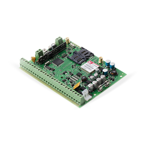
Eldes
Eldes ESIM364 User manual

Eldes
Eldes EWS1 User manual

Eldes
Eldes ESIM264 User manual

Eldes
Eldes ESIM264 User manual
Eldes
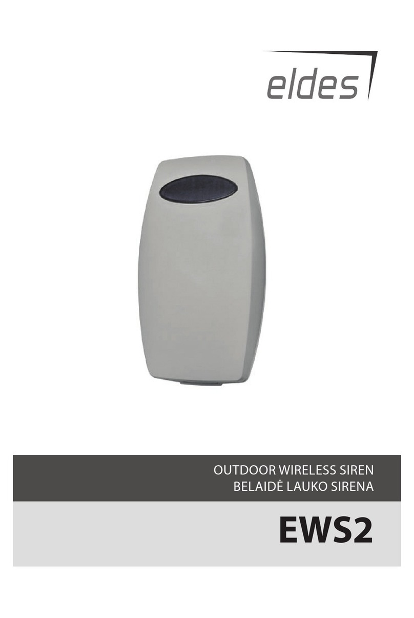
Eldes EWS2 User manual
Eldes
Eldes EPIR2 Instruction sheet

Eldes
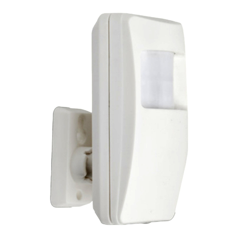
Eldes EPIR2 Installation instructions
Eldes
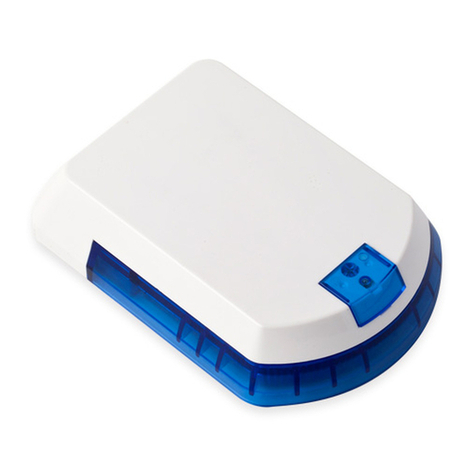
Eldes EWS2 User manual

Eldes
Eldes ESIM264 User manual


