Eldes ESIM264 User manual

ESIM264
GSM ALARM AND MANAGEMENT SYSTEM
USER MANUAL
COMPLIES WITH EN 50131-1 GRADE 2, CLASS II REQUIREMENTS
2
2
EN ESIM264 USER MANUAL V2.3
User Manual v2.3
Valid for ESIM264 v7.15.00 and up
GSM alarm system ESIM264 is a device mounted in limited access areas. Any system repairs must be done only by qualied,
safety aware personnel.
The system must be powered by main 16-24V 50 Hz ~1.5A max or 18-24V 1,5A max DC power supply which must be
approved by LST EN 60950-1 standard and be easily accessible nearby the device. When connecting the power supply to the
system, switching the pole terminals places does not have any aect.
Any additional devices linked to the system ESIM264 (computer, sensors, relays etc.) must be approved by LST EN 60950-1
standard.
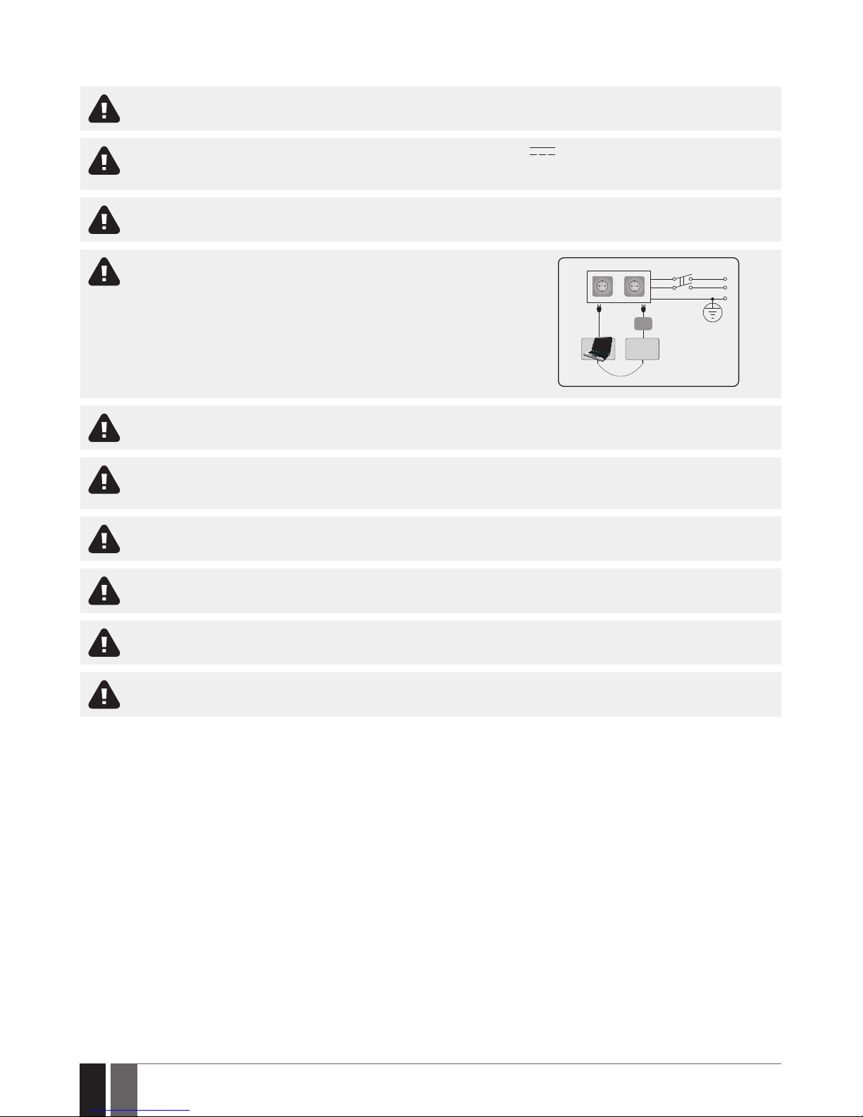
The power supply can be connected to AC mains only inside installation room
with automatic 2-pole circuit breaker capable of disconnecting circuit in the
event of short circuit or over-current condition. Open circuit breaker must have
a gap between connections of more than 3mm (0.12in) and the disconnection
current 5A.
Phase
AC 230V
50 Hz/DC 24V
USB cable
Null
PE
ESIM264
AC/DC
Mains power and backup battery must be disconnected before any installation or tuning work starts. The system installation
or maintenance must not be done during stormy conditions
Backup battery must be connected via the connection which in the case of breaking would result in disconnection of one of
battery pole terminals. Special care must be taken when connecting positive and negative battery terminals. Switching the
pole terminals places is NOT allowed.
In order to avoid re or explosion hazards the system must be used only with approved backup battery.
The device is fully turned o by disconnecting 2-pole switch o device of the mains power and disconnecting backup battery
connector.
Fuse F1 type – Slow Blown 3A. Replacement fuses have to be exactly the same as indicated by the manufacturer.
If you use I security class computer for setting the parameters it must be connected to earth.

3
3
EN
ESIM264 USER MANUAL V2.3
Contents
1. GENERAL INFORMATION.........................................................................................................................................................4
1.1. EKB2 - LCD Keypad ............................................................................................................................................................................................5
1.2. EKB3 - LED Keypad............................................................................................................................................................................................6
1.3. Partitions ............................................................................................................................................................................................................6
2. GENERAL OPERATIONAL DESCRIPTION .................................................................................................................................6
3. BASIC CONFIGURATION AND USE............................................................................................................................................7
3.1. SMS Text Messages ..........................................................................................................................................................................................7
3.2. Password.............................................................................................................................................................................................................8
3.3. System language...............................................................................................................................................................................................8
3.4. User phone numbers ........................................................................................................................................................................................9
3.5. Date and time...................................................................................................................................................................................................11
3.6. User codes ........................................................................................................................................................................................................11
3.7. iButton Keys.....................................................................................................................................................................................................13
4. ARMING AND DISARMING......................................................................................................................................................15
4.1. Free of Charge Phone Call ..............................................................................................................................................................................16
4.2. SMS Text Message...........................................................................................................................................................................................16
4.3. EKB2 Keypad and User Code..........................................................................................................................................................................17
4.4. EKB3 Keypad and User Code..........................................................................................................................................................................17
4.5. iButton Key.......................................................................................................................................................................................................18
4.6. EWK1/EWK2 Wireless Keyfob .......................................................................................................................................................................18
4.7. Arm-Disarm by Zone .......................................................................................................................................................................................19
4.8. Disabling and Enabling Arm/Disarm Notications.....................................................................................................................................19
4.9. Exit and Entry Delay........................................................................................................................................................................................21
4.10. Bypassing and activating zones ...................................................................................................................................................................22
4.11. Stay Mode .........................................................................................................................................................................................................23
4.12. Tampers ............................................................................................................................................................................................................23
4.13. Alarm indications and notications for user.............................................................................................................................................. 24
4.14. Enabling and Disabling Alarm Notications............................................................................................................................................... 26
4.15. Programmable (PGM) outputs.......................................................................................................................................................................27
5. WIRELESS DEVICES............................................................................................................................................................... 28
5.1. Pairing, Removing and Replacing Wireless Device................................................................................................................................... 28
5.2. Wireless Device Information......................................................................................................................................................................... 28
5.3. Electrical and Mechanical Characteristics.................................................................................................................................................. 28
6. BACKUP BATTERY, MAINS POWER STATUS MONITORING AND MEMORY........................................................................... 29
6.1. Backup Battery Status Monitoring .............................................................................................................................................................. 29
6.2. Mains Power Status Monitoring................................................................................................................................................................... 29
7. TEMPERATURE SENSOR ....................................................................................................................................................... 29
7.1. Adding, Removing and Replacing Temperature Sensors ........................................................................................................................ 29
7.2. Setting Up MIN and MAX Temperature Boundaries. Temperature Info SMS ....................................................................................... 30
8. SYSTEM INFORMATION. INFO SMS........................................................................................................................................32
8.1. Periodic Info SMS.............................................................................................................................................................................................32
9. EVENT LOG .............................................................................................................................................................................33
10. INDICATION OF SYSTEM FAULTS .......................................................................................................................................... 34
11. CONTROLLING ELECTRICAL APPLIANCES .............................................................................................................................35
12. IF THE ALARM SYSTEM IS CONNECTED TO A MONITORING STATION.................................................................................. 36
13. TECHNICAL SPECIFICATIONS.................................................................................................................................................37
13.1. Electrical & Mechanical Characteristics.......................................................................................................................................................37
13.2. Main unit, LED and Connector functionality.............................................................................................................................................. 38
13.3. Wiring Diagrams ............................................................................................................................................................................................. 39
14. ADDITIONAL INFORMATION ..................................................................................................................................................41

4
4
EN ESIM264 USER MANUAL V2.3
CONTENTS OF PACK
Element Quantity
1. ESIM264............... .............................................1
2. Microphone.......................................................1
3. SMA antenna......... ...........................................1
4. Buzzer................................................................1
5. Back-up battery connection wire... ..............1
6. User manual......................................................1
7. Resistors 5,6kΩ......................... ...................... 6
8. Resistors 3,3kΩ............................................... 6
9. Plastic standos................ ............................. 4
1. GENERAL INFORMATION
Functionality
ESIM264 – micro-controller based alarm system for houses, cottages, country homes, garages and other buildings, also capable of manag-
ing electrical appliances via cellular GSM/GPRS network. It can also be used as Intercom system.
Examples of using the system:
• Property security.
• Alarm switch.
• Thermostat, heating and air-conditioner control, temperature monitoring.
• Lighting, garden watering, water pump and other electrical equipment control via SMS text messages.
• Remote listening to what is happening in the secured area.
• Main 230V power status with SMS text message.
• Two-way intercom device via GSM network.
Short Description of Main Denitions
The following table provides the explanation of main denitions which are met in this user manual.
Denition Description
System; alarm system ESIM264 device
SMS Short Message Service text
Keyboard Device with a set keys allowing to congure & control the system, view violated zones & system troubles
EKB2 Model of LCD keyboard
EKB3 Model of LED keyboard
EWK1 Wireless keyfob model
EWK2 Wireless keyfob model
User phone number; User 1... 5 Phone number of the user allowed to control the system
System phone number Phone number of the SIM card inserted in ESIM264 device
User password 4-digit combination intended for system arming/disarming using a keyboard
iButton® key Small metal tab containing a unique ID code intended for system arming/disarming
Zone Alarm system input for wired and wireless sensor connection
PGM output Alarm system output for connection of electrical appliances (heating, lighting, gates etc.)
Partition Section dividing one alarm system into two independent parts software-wise

5
5
EN
ESIM264 USER MANUAL V2.3
1.1. EKB2 - LCD Keypad
Main features:
• Alarm system arming and disarming
• Arming and disarming in Stay mode
• System parameter conguration
• PGM output control
• System information display
• Keypad partition switch
• Audio indication by built-in buzzer.
• Wireless device information display
• Temperature display
• Time display
For more details on technical specications and installation, please refer to the latest installation manual of the device located at www.eldes.
lt/download
Icons and Messages
READY
GARAGE
TBL
BYP
STAY
00:4520,20C
GSM signal
strength
System
status
message
Home screen
view
One or more
violated
zones are
bypassed
System
armed in Stay
mode
One or
more
system
faults are
present
Custom
partition
name
Digital
clock
Temperature
1
Icon / Message Description
Chime - Delay zone violated when system
is disarmed.
Exit delay countdown initiated.
System is armed and menu is locked.
System is disarmed and menu is unlocked
+ CONFIGURATION
MODE
Conguration mode activated.
BURGLARY ALARM Delay, Instant or Follow zone violated
when system is armed.
Icon / Message Description
24 ALARM 24H zone violated.
FIRE ALARM Fire zone violated.
TAMPER ALARM Tamper violated
READY System is ready to be armed.
NOT READY System is not ready to be armed – one or
more zones / tampers violated.
ARMED System is armed (optional feature).
STAY Stay mode activated
BYP System armed in Stay mode
TBL One or more system faults are present
Other manuals for ESIM264
6
Table of contents
Other Eldes Security System manuals


Popular Security System manuals by other brands


Secure
Secure USAB-1 operating instructions

B&B
B&B 480 SERIES Operation & maintenance manual

ADEMCO
ADEMCO VISTA-20P Series Installation and setup guide

Inner Range
Inner Range Concept 2000 user manual

Johnson Controls
Johnson Controls PENN Connected PC10 Install and Commissioning Guide

Aeotec
Aeotec Siren Gen5 quick start guide


