© EA Elektro-Automatik, DE-41747 Viersen, Helmholtzstr. 31-37, Tel. 02162-3785-0, Fax. 02162-16230
9
Betriebsartenanzeigen
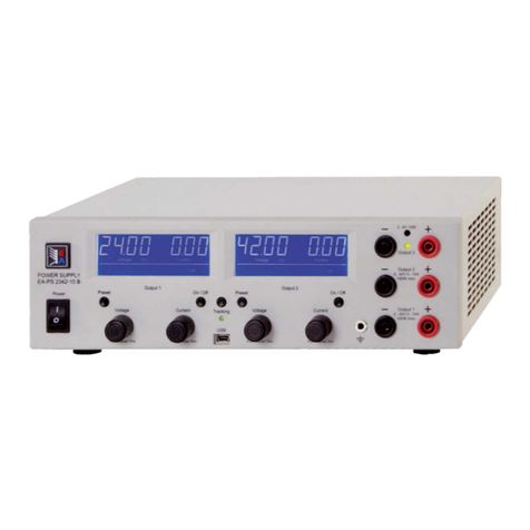
Mit der LED "CV" wird angezeigt, daß das Gerät als Kon-
stantspannungsquelle, und mit der LED "CC", daß das
Gerät als Konstantstromquelle, arbeitet.Diese Umschaltung
geschieht vollautomatisch.
Überlastschutz & Stromregelung
Der Ausgang ist dauerkurzschlußfest. Der max. Strom läßt
sich kontinuierlich von 0 bis Nennstrom einstellen.
Fernsteuerung über analoge Schnittstelle
Über die analoge Schnittstelle besteht die Möglichkeit
Spannung und Strom fernzusteuern, sowie die aktuellen
Strom und Spannungswerte auszuwerten. Die maximalen
Spannungs- und Stromwerte sind dabei auf 10 V bezogen,
das entspricht dann je 100% Nennwert U oder I.
Die Leitungsenden sollten mit einem Widerstand und einem
KondensatorzurUnterdrückungvonStöreinüssenabge-
schlossen werden, z.B. 100 kOhm und 470nF. Die Monito-
rausgänge sind kurzschlußfest und mit 1 mA belastbar. Es
sollte eine geschirmte Leitung verwendet werden, wobei der
Schirm geräteseitig an Pin 10 angeschlossen wird und am
LeitungsendeoenbleibtodermitdemSignalGNDver-
bunden wird. Das Gehäuse des 15 poligen D-Sub-Steckers
hat Schutzleiterverbindung und sollte nicht mit dem Schirm
der Signalleitung verbunden werden.
Die beiden Sollwerte für Spannung und Strom können
einzelnodergemeinsamüberdieenstsprechendenSteu-
ereingänge vorgegeben werden. Wenn nur einer genutzt
werden soll, bleibt der jeweils andere zum Potentiometer
anderFrontgebrückt.
DurchÖnenderBrückeundVorgabedesSollwertesam
Pin UPS oder IPS erfolgt automatisch Fernsteuerung. Dazu
werden die Verbindungen am mitgelieferten Stecker Pin 3
und4(fürSpannung)sowiePin5und6(fürStrom)geönet.
Bei Verwendung eines externen Potentiometer kann die +
Referenz (Pin 2) mit einer Seite des Potentiometers und
die 0 V-Referenz (Pin 1) mit der anderen Seite des Poten-
tiometers verbunden. Der Schleifer wird dann mit UPS (Pin
3, Spannung) bzw. mit IPS (Pin 5, Strom) verbunden. Pin
2 und Pin 4 bleiben dann unbenutzt.
DieMonitorsignalefürSpannungs-undStromistwertsind
ohne weitere Beschaltung an den entsprechenden Pins
verfügbar.Pin7=IMON bzw. Pin 8 = UMON.
Ferngesteuert den DC-Ausgang ein-/ausschalten
MitdemSB(Pin9)kanndasSchaltnetzteilindenStand-by
Betrieb versetzt werden. Dazu muß Pin 9 mit +5 V Pin 12
verbundenwerden,z.B.übereinenRelaiskontakt.Wird
dieseVerbindungwiedergeönet,steigtdieAusgangsspan-
nung wieder mit Softstartverhalten auf den voreingestellten
Spannungssollwert an.
Mode indication
If the LED "CV" is lit, the unit operates as a constant volt-
age source, while the LED "CC" indicates that the unit is
operating as a constant current source. The change-over
happensautomatically.
Overload protection and current regulation
The output is protected against a continuous short-circuit.
The max. output current is continuously adjustable from
zero up to the rated current.
Remote control via analog interface
Itispossibletocontroloutputvoltageandcurrentexternally
via the analogue interface as well to monitor the actual
valuesexternally.Themaximumratedvoltageandcurrent
values are standardized to 10 V, corresponding to 100%
U or I.
Theendsofthemonitorcableshouldbeterminatedbya
resistor and capacitor, for example 100 kOhm and 470 nF.
The monitor outputs are short-circuit protected and the max.
load is 1 mA. The cable should be screened. The screen
must be connected to Pin 10 (GND).
The housing of the 15-pole Sub-D plug is connected to PE
andmay notbe connectedtothe screenof themonitor
cable.
The voltage and current values can both be set via the high
impedance control inputs.
The two set values of voltage and current can be supplied
standalonebutalsotogether.Incaseonlyoneisgoingto
be used for remote control, the other is left bridged to the
potentiometer on the front.
Byopeningthebridgesandsupplyingthe0-10Vfroman
external source or external potentiometer to input UPS or
IPSthedeviceisautomaticallyinremotecontrol.Todothat
the connections on the supplied 15-pole plug on pins 3 and 4
(for voltage) and pins 5 and 6 (for current) must be opened.
When using an external potentiometer, the + reference (pin
2) can be connected to one side of the potentiometer and the
0 V reference (pin 1) to the other side of the potentiometer.
The slider of the potentiometer is then connected to either
UPS (pin 3, voltage) or IPS (pin 5, current). Pins 2 and 4
are then left unused.
The monitor signals are available on the respective outputs
pin 7 = IMON and pin 8 = UMON.
Remotely switching the DC output on/o
Through the control input SB (Pin 9) the unit can be switched
intostandbymode(outputvoltageo).Thisiseectedby
connectingPin9to+5VPin12,forexamplethrougharelay
contact. After opening this connection the output is switched
on again and rises up to the preset value.
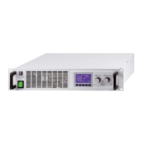
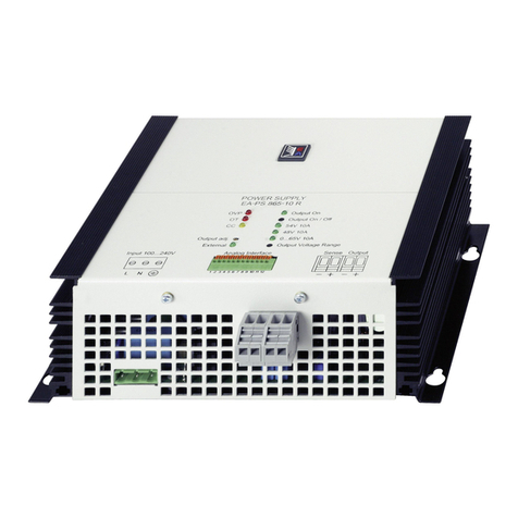
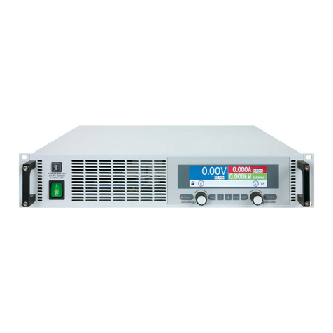
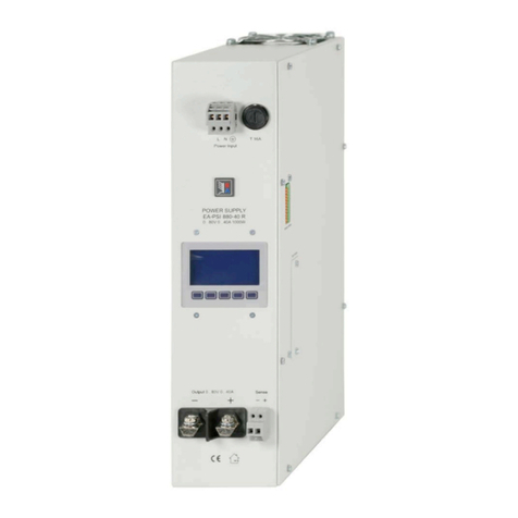
Beschreibung / Description


