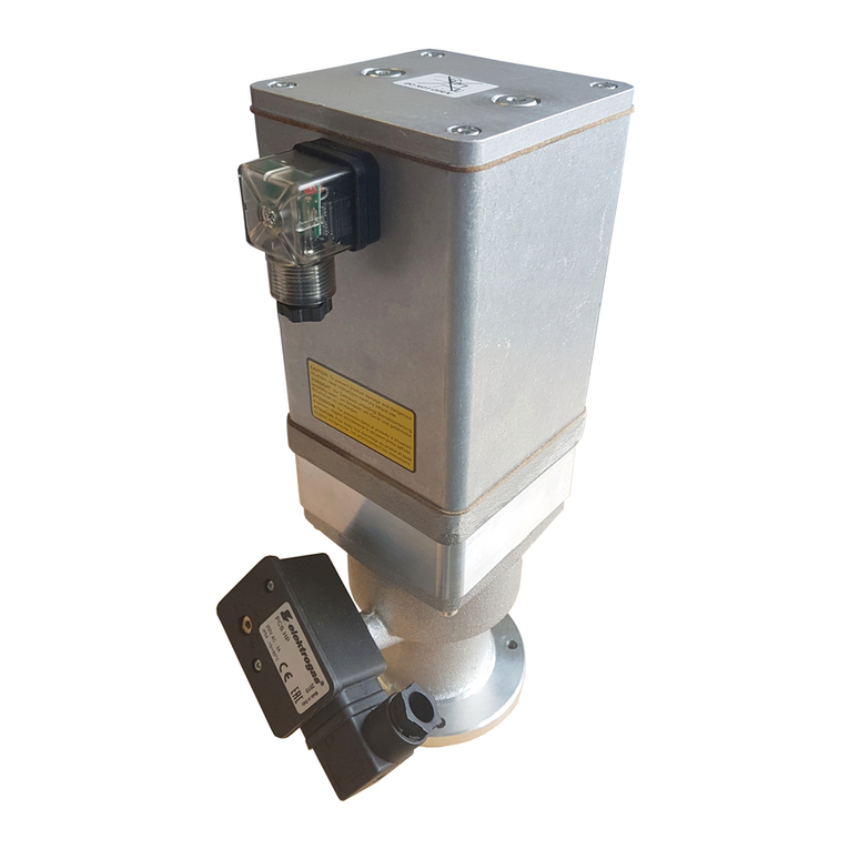
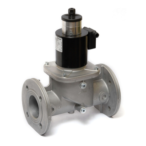
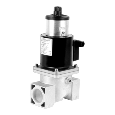
Elektrogas EVRM-NA User manual

Rev. - 1112
GB SAFETY SOLENOID VALVES FOR AIR AND GAS WITH MANUAL RESET
NORMALLY OPEN - CLOSED ONLY WHEN ENERGIZED
I ELETTROVALVOLE DI SICUREZZA PER ARIA E GAS A RIARMO MANUALE
NORMALMENTE APERTE - CHIUSE SOTTO TENSIONE
D SICHERHEI TSMAGNETVENTILE FÜR LUFT UND GAS MIT MANUELLER RÜCKSTELLUNG
STROMLOS GEÖFFNET- UNTER SPANNUNG GESCHLOSSEN
F ELECTROVANNE DE SECURITE POUR L’AIR ET LE GAZ A REARMEMENT MANUEL
NORMALEMENT OUVERTE - FERMEE SOUS TENSION
E ELECTROVALVULA DE SEGURIDAD PARA AIRE Y GAS DE REARME MANUAL
NORMALMENTE ABIERTA - CERRADA CON TENSION
RU ЭЛЕКТРОМАГНИТНЫЕ ПРЕДОХРАНИТЕЛЬНЫЕ КЛАПАНЫ ДЛЯ ВОЗДУХА ИГАЗА СРУЧНЫМ
ВЗВОДОМ, ОТКРЫТЫЕ ВОБЕСТОЧЕННОМ СОСТОЯНИИ ИЗАКРЫТЫЕ
ПРИ ПОДАЧЕ НА НИХ НАПРЯЖЕНИЯ
CN 安全电磁阀为空气和气体以手控复位 重新设置用手 - 关闭只当电能被提供
EVRM-NA
EVRM-6NA
ELETTROMECCANICA DELTA S.p.A.
31030 Arcade (TV) ITALY
www.elektrogas.com
0497

Declaration of Conformity
Dichiarazione di Conformità
Konformitätserklärung
Déclaration de Conformité
Declaración de Conformidad
EVRM-NA
Description / Type Solenoid safety valves for gas
EVRM-6NA
Descrizione / Tipo Valvole elettromagnetiche di sicurezza per gas
Beschreibung / Typ Elektromagnetisches Sicherheitsventil für Gas
Description / Type Electrovanne automatique de securite pour le gaz
Descripción / Tipo Electrovalvula automatica de seguridad para gas
Manufacturer / Address ELETTROMECCANICA DELTA S.p.A.
Costruttore / Indirizzo Via Trieste, 132
Hersteller / Adresse 31030 Arcade (TV)
Fabricant / Adresse ITALY
Fabricante / Dirección
CE certificate PED/0497/899/07, PED/0497/900/07
Certificato CE CSI S.p.A. viale Lombardia 20, 20021 BOLLATE (MI)
CE-zertifiziert Notified body 0497
certifié CE 16.07.2007
Certificado CE
EC Surveillance 97/23/EC Cat. II, annex III, module D1
Sorveglianza CE CSI S.p.A. viale Lombardia 20, 20021 BOLLATE (MI)
EG-Überwachung Notified Body 0497
Surveillance CE
Vigilancia CE
Certified Quality System EN ISO 9001
Sistema Qualità Certificato KIWA Italia S.p.A.
Zertifiziertes Qualitätssystem KI - 0503291/01
Système de Qualité Certifié
Sistema de Calidad Certificado
Comply with the essential requirements of the following European Directives and their amendments:
Conformi ai requisiti essenziali delle seguenti Direttive Europee e loro successive modifiche:
Erfüllen die wesentlichen Anforderungen der folgenden Europäischen Richtlinien und deren Änderungen:
Se conformer aux exigences essentielles des Directives Européennes suivantes et leurs modifications:
Cumplir con los requisitos esenciales de las siguientes Directivas Europeas y sus modificaciones:
97/23/EC Reg.-Nr. PED/0497/899/07, PED/0497/900/07
2006/95/EC, 2004/108/EC
94/9/EC when shown on the product II 3G II 3D
quando indicato sul prodotto Ex nA II T4 X Ta -15°/+40°C
wenn auf dem Produkt angegeben Ex tD A22 IP54 T135 X
lorsqu'on lui a montré sur le produit Ex tD A22 IP65 T135 X
cuando se muestra en el producto
Standards / Norme / Normen / Normes / Normas:
EN 13611, EN 60529, EN 60730-1, EN 60335-1, EN 55014-1, EN 55014-2
EN 60079-0, EN 60079-15, EN 61241-0, EN 61241-1
Arcade, 20.01.2010
Product Quality Manager Development & Technical Manager

Model
600 mbar
(60 kPa)
Model
6 bar
(600 kPa)
Connec-
tions V’ Air
∆p=1mbar
(m
3
/h)
Power
@230V
(W)
Fmax
t<10s
(Nm)
Tmax
(Nm)
Cmax
(Nm)
Overall
Dimensions
(mm)
Weight
(Kg)
EVRMNA0O EVRM6NA0O Rp 3/8 0,6 16 70 35 - 58x130x30 0,4
EVRMNA1O EVRM6NA1O Rp 1/2 0,9 16 105 50 - 58x130x30 0,4
EVRMNA2O EVRM6NA2O G 3/4 1,8 16 225 85 - 55x130x35 0,6
EVRMNA3O EVRM6NA3O G 1 3,6 16 340 125 - 62x137x40 0,7
EVRMNA0 EVRM6NA0 Rp 3/8 2,5 16 70 35 - 77x148x70 0,6
EVRMNA1 EVRM6NA1 Rp 1/2 3,5 16 105 50 - 77x148x70 0,6
EVRMNA2 EVRM6NA2 Rp 3/4 8,5 16 225 85 - 96x165x85 0,8
EVRMNA3 EVRM6NA3 Rp 1 10 16 340 125 - 96x165x85 0,8
EVRMNA35 EVRM6NA35 Rp 11/4 18 16 475 160 - 153x203x120
1,6
EVRMNA4 * EVRM6NA4 * Rp 11/2 23 16 610 200 - 153x203x120
1,6
EVRMNA6 * EVRM6NA6 * Rp 2 35 16 1100 250 - 156x213x106
1,9
EVRMNA7T EVRM6NA7T Rp 21/2 55 19 1600 325 - 218x295x175
6,1
EVRMNA7 EVRM6NA7 DN 65 55 19 1600 - 50 305x350x200
8,2
EVRMNA8 EVRM6NA8 DN 80 70 19 2400 - 50 305x350x200
8,2
EVRMNA9 EVRM6NA9 DN 100 130 19 5000 - 80 350x410x252
16
EVRMNA93 EVRM6NA93 DN 125 220 19 6000 - 160 460x500x310
28
EVRMNA95 EVRM6NA95 DN 150 280 19 7600 - 160 460x500x310
30
EVRMNA98 EVRM6NA98 DN 200 460 19 7600 - 160 546x590x370
45
...O = Brass (*) Flanged kit available

SAFETY SOLENOID VALVE FOR GAS
EVRM-NA / EVRM-6NA
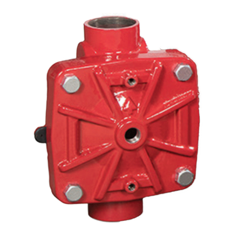
The EVRM-NA type valve is a manual reset safety valve that is normally open. A manual operation is
therefore necessary to open the valve and set the mechanism consenting to maintain this state.
The powering by means of line current and/or condenser discharge, induced by the leakage detector,
causes tripping of the mechanism and consequent closing of the gas passage. If energizing of the sensor
persists due to the presence of gas, the valve remains under power and does not allow reset. When the
causes for locking have been eliminated, the valve may be reopened by working it manually. This type of
device, connected with one or more leakage detectors or alarm signals for the presence of carbon
monoxide, is suitable for performing locking operations on the gas line.
1- INSTALLATION (Qualified technicians only)
Shut off the gas supply and electrical power before servicing any part of the system.
Check correspondence of flow direction with arrow printed on valve body, check correct alignment of
connecting pipes. Avoid overtightening and use proper tools only. Valve may be mounted with coil in
horizontal or vertical position. Coil may be oriented 360 degrees in any direction. Install in an area that is
protected from rain and water splashes or drops.
2- ELECTRICAL CONNECTION (IEC 730-1)
Using a screwdriver remove the DIN plug from the coil and connect power cables to the clamps according to
printed designation. When reassemble use cable gland properly.
Perform leak and functional tests after mounting.
3- OPENING FUNCTION
To open the valve remove the plastic cap, pull the knob completely up to complete resetting. Put back the
plastic cap. The 6 bar type requires pressure compensation: pull the knob for the first step, wait some
moment, and then pull the knob completely up to full resetting (from 3/4” to 6”).
4- CLEANING AND MAINTENANCE
Dust and any foreign bodies may be easily removed from the filter or the gas passage zone. After shutting
off upstream gas and electric current, reset the valve. Coil is removed by unscrewing the reset knob and the
fastening cap. Unscrew the screws fixing the counter flange to valve body. During this operation care should
be taken not to cause damage to the sealing lip.
Do not dismount or tamper with the resetting mechanism.
5- TECHNICAL SPECIFICATIONS
Connections : gas threaded ISO 7-1 from Rp3/8 to Rp2½
: flanged PN16 – ISO 7005 from DN40 to DN200
Voltage rating : 230VAC, 110VAC, 24V AC/DC, 12VDC
Voltage tolerance : -15% / +10%
Ambient temperature : -15°C / +60°C
Max. operating pressure : 600 mbar or 6 bar
Closing time : < 1 second
Protection class (EN 60529) : IP 54
Cable gland : PG 9
Pressure inlets : G1/4 on two sides (except brass models)
Limit switch : by request from 3/4" to 8"
Strainer : 600 µm (except brass models)
Gas type (EN 437) : Air and non-aggressive gases 1, 2 and 3
(gaseous state only)
Comply with the essential requirements of the following Directives:
97/23/EC, 2006/95/EC, 2004/108/EC.
This control must be installed in compliance with the rules in force.
Elektrogas reserves the right to update or make technical changes without prior notice.
GB

ELETTROVALVOLA DI SICUREZZA PER GAS
EVRM-NA / EVRM-6NA
L'elettrovalvola tipo EVRM-NA è una valvola di sicurezza normalmente aperta a riarmo manuale. E’ quindi
indispensabile un intervento manuale per aprire la valvola e armare il meccanismo che consente il
mantenimento di questo stato.
La messa in tensione con corrente di linea e/o scarica di condensatore, indotta dal rilevatore di fughe,
provoca lo sganciamento del meccanismo e la conseguente chiusura del passaggio gas. Perdurando
l’eccitazione del sensore a causa della presenza di gas, la valvola resta sotto tensione e non permette il
riarmo. Dopo aver eliminato le cause del blocco è possibile riaprire la valvola intervenendo manualmente.
Questo tipo di dispositivo, in connessione con uno o più rilevatori di fughe gas o segnali di allarme per la
presenza di ossidi di carbonio, è adatto per attuare manovre di blocco della linea gas.
1- INSTALLAZIONE (Solo personale qualificato)
Chiudere il gas e scollegare l'alimentazione prima di eseguire qualsiasi intervento all'impianto.
Verificare la concordanza tra il senso del flusso e la freccia in rilievo sul corpo valvola, controllare il corretto
allineamento delle tubazioni di attacco. Evitare serraggi eccessivi e utilizzare solo attrezzi adeguati. La
valvola può essere montata con bobina orizzontale o verticale. La bobina può essere a sua volta orientata in
qualsiasi direzione su 360°. Installare in zona protetta dalla pioggia, da spruzzi o da gocciolamenti d’acqua.
2- COLLEGAMENTO ELETTRICO (IEC 730-1)
Usando un cacciavite rimuovere il connettore dalla bobina e collegare i cavi ai morsetti, rispettando la
simbologia indicata. Durante il riassemblaggio utilizzare correttamente il pressacavo.
Eseguire sempre un test funzionale e di tenuta dopo l'installazione.
3- FUNZIONE DI APERTURA
Per riaprire la valvola rimuovere il cappuccio in plastica, tirate il pomello fino al riarmo della valvola. Quindi
rimettere il cappuccio. La versione 6 bar richiede la compensazione della pressione: per aprire la valvola
tirare il pomello per il primo tratto, attendere qualche istante, quindi tirare completamente fino al riarmo
completo (da 3/4" a 6”).
4- PULIZIA E MANUTENZIONE
Polvere ed eventuali corpi estranei possono essere facilmente rimossi dal filtro o dalla sede di passaggio del
gas. Dopo aver chiuso il gas a monte e tolto la corrente, riarmare la valvola. La bobina si rimuove svitando il
pomello di riarmo e il cappuccio di fissaggio. Svitare quindi le viti che fissano la controflangia al corpo
valvola. Durante questa operazione aver cura di non danneggiare la sede dell’otturatore.
Non smontare o manomettere il meccanismo di riarmo.
5- CARATTERISTICHE TECNICHE
Attacchi : filettati gas ISO 7-1 da Rp3/8 a Rp2½
: flangiati PN16 – ISO 7005 da DN40 a DN200
Tensione nominale : 230VAC, 110VAC, 24V AC/DC, 12VDC
Tolleranza su tensione : -15% / +10%
Temperatura ambiente : -15°C / +60°C
Massima pressione di esercizio : 600 mbar oppure 6 bar
Tempo di chiusura : < 1 secondo
Grado di protezione (EN 60529) : IP 54
Pressacavo : PG 9
Prese di pressione : G1/4 su due lati (esclusi modelli con corpo in ottone)
Finecorsa : A richiesta da 3/4" a 8"
Filtro : 600 µm (esclusi modelli con corpo in ottone)
Tipo di gas (EN 437) : Aria e gas non aggressivi 1, 2 e 3
(solo stato gassoso)
Conformi ai requisiti essenziali delle seguenti Direttive:
97/23/CE, 2006/95/CE, 2004/108/CE.
Questo controllo deve essere installato in accordo con le leggi in vigore.
Elektrogas si riserva la facoltà di apportare aggiornamenti o modifiche tecniche senza preavviso.
I

SICHERHEITS-MAGNETVENTIL FUER GAS
EVRM-NA / EVRM-6NA
Das Magnetventil EVMR-NA ist ein stromlos offenes Sicherheitsventil mit manuellem Reset. Um das Ventil
zu öffnen und es in diesem Zustand zu fixieren, ist manueller Eingriff erforderlich.
Wird Netzspannung angelegt und/oder die Spule durch Kondensatorentladung eines Leckortungsgerätes
erregt, so löst sich die Verriegelung des Ventils und der Gasdurchfluß wird gestoppt. Solange der Sensor
Gas feststellt, bleibt das Ventil unter Spannung und gestattet kein Reset. Nach Beseitigung der
Auslöseursache läßt sich das Ventil manuell wieder öffnen. Dieses Sicherheitsventil eignet sich in
Verbindung mit einem oder mehreren Gasleckdetektoren bzw. mit akustischem Alarm für die
Notabschaltung der Gasleitung im Falle von Gasaustritt.
1- INSTALLATION (Nur durch qualifizierte Techniker)
Vor Durchführung von Arbeiten Gaszufuhr absperren und Anlage spannungsfrei schalten.
Das Ventil ist in Durchflußrichtung (siehe Reliefpfeil auf dem Ventilkörper) zu montieren, die
Anschlußrohrleitungen sind korrekt auszurichten. Vermeiden Sie es, zu fest anzuziehen und verwenden Sie
nur geeignetes Werkzeug. Das Ventil kann mit der Spule sowohl in horizontaler als auch in vertikaler
Position montiert werden. Die Spule kann beliebig um 360° gedreht werden. Das Ventil ist so zu installieren,
daß es vor Regen, Spritzwasser und Wassertropfen geschützt ist.
2- ELEKTRISCHER ANSCHLUSS (IEC 730-1)
Der DIN Stecker wird mit einem Schraubenzieher von der Spule entfernt und die Anschlußkabel an die
Klemmplatte entsprechend der Kennzeichnung angeschlossen. Benutzen Sie die Kabelschelle zur richtigen
Fixierung des Anschlußkabels.
Nach Abschluß der Arbeiten ist eine Dichtheits- und Funktionskontrolle durchzuführen.
3- ÖFFNEN DES VENTILS
Um das Ventil zu öffnen, entfernen Sie die Plastikkappe und ziehen den Drehknopf vollständig bis zum
kompletten Zurückstellen heraus. Setzen Sie dann die Plastikkappe wieder zurück. Das 6 bar Modell
erfordert einen Druckausgleich: Ziehen Sie hierzu den Drehknopf in die erste Position, warten Sie einen
Moment für den Druckausgleich und ziehen Sie dann den Drehknopf bis zum Anschlag zur vollständigen
Rückstellung (von 3/4 "bis 6").
4- REINIGUNG UND WARTRUNG
Staub und andere Fremdkörper können sehr leicht vom Filter bzw. vom Ventilsitz entfernt werden. Nachdem
Gas- und Stromversorgung getrennt wurden, öffnet man das Ventil. Die Spule wird abgenommen, indem der
Resetknopf und die Sechskantmutter herausgedreht werden. Anschließend sind die Schrauben, die den
Gegenflansch mit dem Ventilkörper verbinden, herauszudrehen.
Bei diesem Arbeitsvorgang ist darauf zu achten, daß der Verschlußsitz nicht beschädigt wird.
Der Resetmechanismus darf nicht auseinandergebaut bzw. nicht verändert werden.
5- TECHNISCHE EIGENSCHAFTEN
Anschlüsse : Gewindeanschlüsse ISO 7-1 von Rp3/8 bis Rp2½
: Flanschanschlüsse PN16-ISO 7005 von DN40 bis DN200
Betriebsspannungen : 230VAC, 110VAC, 24V AC/DC, 12VDC
Zul. Spannungstoleranzen : -15% bis +10%
Zul. Umgebungstemperatur : -15°C bis +60°C
Max. Arbeitsdruck : 600 mbar oder 6 bar
Schließzeit : < 1 Sekunde
Schutzklasse (EN 60529) : IP 54
Kabelschelle : PG 9
Druckmeßanschlüsse : G1/4 beidseitig (ausgenommen Modelle mit Messingkörper)
Endschalter : Auf Anfrage von 3/4" bis 8"
Filter : 600 µm (ausgenommen Modelle mit Messingkörper)
Gasart (EN 437) : Luft und nicht aggressive Gase 1, 2 und 3
(Flüssiggas nur gasförmig)
Die grundlegenden Anforderungen folgender Richtlinien werden erfüllt:
97/23/EWG, 2006/95/EG, 2004/108/EG.
Dieses Sicherheitsventil muß in Übereinstimmung mit den geltenden Gesetzen installiert werden.
Technische Änderungen vorbehalten.
D

ELECTROVANNE DE SÛRETÉ POUR LE GAZ
EVRM-NA / EVRM-6NA
L'électrovalve de type EVRM-NA c'est une vanne de sûreté normalement ouverte à réarmement manuel. Il
est donc nécessaire une intervention manuelle pour ouvrir la vanne et armer le dispositif qui permet de
garder cet état.
La mise sous tension avec du courant de réseau et/ou décharge de condensateur, induite par le détecteur
de fuites, entraîne le décrochage du dispositif et par conséquent la fermeture du passage de gaz. Si
l'excitation du senseur continue à cause de la présence de gaz, la vanne reste sous tension et ne permet
pas le réarmement. Après avoir éloigné les causes de l'anomalie, il est possible de rouvrir la vanne en
intervenant manuellement. Ce type de dispositif, en liaison avec un ou plusieurs détecteurs de fuites de gaz
ou avec des signaux d'alarme pour la présence d'oxydes de carbone, est apte pour exécuter des
manoeuvres d'arrêt de la ligne de gaz.
1- INSTALLATION (Seulement techniciens qualifies)
Fermer l’alimentation gaz et mettre l'installation hors tension avant d’effectuer toute intervention.
Vérifier la concordance entre le sens du débit et la flèche en relief sur le corps de la vanne, contrôler le juste
alignement des tuyaux de branchement. Évitez de trop serrer et utilisez les outils appropriés. La vanne peut
être montée avec la bobine horizontale ou verticale. La bobine peut être elle même orientée dans n'importe
quelle direction sur 360°. L'installer dans un endroit protégé de la pluie, des jets ou des égouttements d'eau.
2- BRANCHEMENT ELECTRIQUE (IEC 730-1)
En utilisant un tournevis enlevez la prise DIN de l'enroulement et reliez les cables électriques aux brides
selon la désignation imprimée. Quand rassemblez la glande de câble d'utilisation correctement.
Après le montage, procéder toujours à un contrôle d'étanchéité et de fonctionnement.
3- FONCTION D'OUVERTURE
Pour ouvrir la valve enlèvent le chapeau en plastique, tirent le bouton complètement jusqu'au rajustement
complet. Remis le chapeau en plastique. Le type 6 bar exige la compensation de pression : tirez le bouton
pour la première étape, attendez un certain moment, et puis tirez le bouton complètement
jusqu'complètement au rajustement (de 3/4 "à 6").
4- NETTOYAGE ET ENTRETIEN
On peut facilement nettoyer le filtre ou le logement de passage du gaz de la poussière et de toute autre
particule étrangère. Après avoir fermé le gaz à l'amont et coupé la tension, réarmer la vanne. La bobine se
déplace en dévissant la poignée de réarmement et le capuchon de fixation. Dévisser ensuite les vis qui
fixent la contre-bride au corps de la vanne. Pendant cette opération, faire attention à ne pas endommager le
logement du clapet.
Eviter de démonter ou d'abîmer le dispositif d'armement.
5- CARACTERISTIQUES TECHNIQUES
Raccords : filetés gaz ISO 7-1 de Rp3/8 à Rp2½
: à brides PN16 - ISO 7005 de DN40 à DN200
Tension nominale : 230VAC, 110VAC, 24V AC/DC, 12VDC
Marge de tension : -15% / +10%
Température ambiante : -15°C / +60°C
Pression de travail maxi. : 600 mbar ou 6 bar
Temps de fermeture : <1 seconde
Degré de protection (EN 60529) : IP 54
Presse à câbles : PG 9
Prises de pression : G1/4 sur deux côtés (exclu sur le modèle en laiton)
Fin de course : Sur demande de 3/4" à 8"
Filtre : 600 µm (exclu sur le modèle en laiton)
Type de gaz (EN 437) : Air et gaz non agressifs 1, 2 et 3
(seulement état gazeux)
Réspondent aux exigences essentielles des Directives suivantes:
97/23/CE, 2006/95/CE, 2004/108/CE.
Ce matériel doit être installé en accord avec les lois en rigueur.
Elektrogas se réserve le droit d'apporter des mises à jour ou des modifications techniques sans avis préalable.
F

ELECTROVALVULA DE SEGURIDAD PARA EL GAS
EVRM-NA / EVRM-6NA
La electroválvula del tipo EVRM-NA es una válvula de seguridad normalmente abierta de rearme manual.
Por ello es necesaria la intervención manual para abrir la válvula y armar el dispositivo que permite este
estado. La puesta en tensión con corriente de la red y/o la descarga del condensador, inducida por el
detector de fugas, conlleva el accionamiento del dispositivo y como consecuencia el cierre del paso del gas.
Si la excitación del sensor continua a causa de la presencia de gas, la válvula queda bajo tensión y no
permite su rearme. Una vez eliminada las causas de la anomalía, es posible reabrir la válvula interviniendo
manualmente. Este tipo de dispositivo, en unión con uno o varios detectores de fugas de gas o con señales
de alarmas por la presencia de óxidos de carbono, es apta para realizar maniobras de corte en la línea de
gas.
1- INSTALACION (Solamente técnicos cualificados)
Cortar el suministro de gas y quitar la tensión antes de desmontar cualquier parte del sistema.
Verificar la concordancia entre el sentido del flujo y la flecha en relieve sobre el cuerpo de la válvula,
controlar la adecuada alineación de los tubos de conexión. Evite de apretar demasiado y utilice las
herramientas apropiadas. La válvula se puede montar con la bobina horizontal o vertical. La bobina puede
orientarse ella misma en cualquier dirección de los 360º. Instalarla en un lugar protegida de la lluvia, de los
chorros o de goteos de agua.
2- CONEXION ELECTRICA (IEC 730-1)
Con un destornillador quite el enchufe de la bobina y conecte los cables de transmisión con las abrazaderas
según la designación impresa. Utilice la glándula de cable correctamente.
Realice el escape y las pruebas funcionales después de montar.
3- FUNCIÓN DE LA ABERTURA
Para abrir la válvula quita el casquillo plástico, tira de la perilla totalmente hasta el reajuste completo.
Puesto detrás el casquillo plástico. El tipo de 6 bar requiere la compensación de la presión: tire de la perilla
para el primer paso, espere un cierto momento, y después tire de la perilla totalmente hasta por completo el
reajuste (a partir la 3/4" a el 6”).
4- LIMPIEZA Y MANTENIMIENTO
Se puede limpiar fácilmente el filtro o el alojamiento del paso del gas del polvo o de cualquier otra partícula
extraña. Después de haber cerrado el gas, aguas arriba y quitada la tensión, rearmar la válvula. La bobina
se desplaza soltando la empuñadura de rearme y el capuchón de fijación. Soltar seguidamente los tornillos
que fijan la contrabrida al cuerpo de la válvula. Durante esta operación tener cuidado en no dañar el
alojamiento de la clapeta.
Evitar desmontar o dañar el dispositivo de rearme.
5- CARACTERISTICAS TÉCNICAS
Conexiones H/H : roscadas gas ISO 7-1 de Rp3/8 a Rp2½
: embridadas PN16 - ISO 7005 de DN40 a DN200
Tensión nominal : 230VAC, 110VAC, 24V AC/DC, 12VDC
Tolerancia de tensión : -15% / +10%
Temperatura de trabajo : -15ºC / +60ºC
Presión de trabajo Max. : 600 mbar o 6 bar
Tiempo de cierre : < 1 segundo
Grado de protección (EN 60529) : IP 54
Raccord cables : PG 9
Tomas de presión : G1/4 en los dos lados (salvo en modelos de latón)
Limitador de carrera : bajo pedido desde 3/4” hasta 8”
Filtro : 600 µm (salvo en modelos de latón)
Tipo de gas (EN 437) : Aire y gases no agresivos 1, 2 y 3
(solamente estado gaseoso)
Cumplen con los requisitos básicos de las siguientes directivas:
97/23/CE, 2006/95/CE, 2004/108/CE.
Este material se debe instalar de acuerdo con las normas en vigor.
Elektrogas se reserva el derecho de hacer cambios técnicos sin previo aviso.
E

БЫСТРОДЕЙСТВУЮЩИЙ ПРЕДОХРАНИТЕЛЬНЫЙ КЛАПАН
СЭЛЕКТРОМАГНИТНЫМ УПРАВЛЕНИЕМ - EVRM-NA / EVRM-6NA
Электромагнитный клапан EVRM-NA является предохранительным клапаном сручным взводом висходное
положение, который внормальном состоянии открыт. Для того, чтобы открыть клапан изафиксировать его в
таком положении, необходимо ручное вмешательство оператора.
Вслучае подачи сетевого напряжения или же при возбуждении катушки от разрядки конденсатора прибора,
для определения места повреждения иутечки приводится вдействие блокирую ее устройство клапана и
подача газа прекра ается.
До тех пор, пока чувствительный элемент сенсорного датчика фиксирует наличие газа, клапан находится под
напряжением, ине дает срабатывать механизму взведения.
После устранения причины срабатывания клапана, его можно снова открыть вручную.
Настоя ий предохранительный клапан может быть использован всочетании содним или несколькими
приборами для обнаружения утечки газа либо вместе ссигнализаторами для аварийного отключения и
перекрытия газопровода вслучаях утечки газа.
1- УСТАНОВКА (Квалифицир ванные техники т льк )
Отключите п дачу электр питания перед пр ведением раб т п техническ му бслуживанию.
Клапан необходимо устанавливать впропускном направлении (смотрите рельефное изображение стрелки на
корпусе клапана), соединительные трубопроводы должны быть правильно установлены сцентровкой по
одной оси. Избегите излишек затягивать ииспользуйте правильные инструменты только. Клапан можно
устанавливать скатушкой, расположенной как горизонтально, так ивертикально. Катушку можно
поворачивать, по своему усмотрению, на 360°. Клапан необходимо устанавливать таким образом, чтобы он
был за и ён от попадания на него дождя икапель воды.
2- ЭЛЕКТРИЧЕСКОЕ ПОДКЛЮЧЕНИЕ (IEC 730-1)
Для электрического подключения необходимо снять крышку штекерного разъёма иподсоединить кабель к
клеммному зажиму выпрямителя (!). Используйте правильно зажим для крепления кабеля.
Вып лните утечку ифункци нальные испытания п сле устанавливать.
3- ФУНКЦИЯ ОТВЕРСТИЯ
Для того чтобы раскрыть клапан извлекайте пластичную крышку, вытяните ручку вполне до вполне возврата.
Положите назад пластичную крышку. Тип 6 штанг требует компенсации давления: вытяните ручку для
первыйа шаг, ждите некоторый момент, ипосле этого вытяните ручку вполне до полного возврата (от 3/4 "до
6").
4- ОЧИСТКА ИТЕХНИЧЕСКОЕ ОБСЛУЖИВАНИЕ
Пыль идругие инородные частицы очень легко можно убрать сфильтра или из мест прохождения газа. После
прекра ения подачи газа иэлектропитания, вскройте клапан. Необходимо выта ить катушку, открутив для
этого рукоятку взведения икрепежную гайку. Взаключение необходимо открутить 4 винта, соединяю ие
крышку скорпусом клапана. Во время этой рабочей операции следует следить за тем, чтобы седло затвора
клапана не было бы повреждено. Обслуживание латунных клапанов не предусмотрено.
Нельзя разбирать или менять чт -либ вустр йстве механизма взв да.
5- ТЕХНИЧЕСКИЕ ХАРАКТЕРИСТИКИ
соединения : резьбовые соединения согласно ISO 7-1
от Rp3/8 до Rp2½ (дюймов)
фланцевые соединения PN16-ISO 7005
сноминальным диаметром (НД) от 40 до 200
максимально допустимое напряжение : 230 VAC, 110 VAC, 24V AC/DC, 12VDC
допуски перепадов напряжения : от -15 % до +10 %
температура окружаю ей среды : от -15 °Сдо +60 °С
максимальное рабочее давление : 600 mBar или 6 Bar
время закрытия клапана : < 1 секунда
класс за иты (EN 60529) : IP 54
зажим для крепления кабеля : PG 9
подключение для измерения давления : G1/4 собеих сторон (за исключением модели из латунного корпуса)
концевой выключатель : по запросу (от 3/4" до 8")
фильтр : 600 µm (за исключением модели из латунного корпуса)
вид газа EN 437) : воздух инекоррозионные газы 1, 2 и3 (газообразное только)
Следуйте сн вным бязательным треб ваниям следующих директив:
97/23/EC, 2006/95/EC, 2004/108/EC.
Настоя ий предохранительный клапан должен устанавливаться всоответствии сдействую им
законодательством. Компания оставляет за собой право на внесение технических изменений.
RU

燃气安全电磁阀
燃气安全电磁阀燃气安全电磁阀
燃气安全电磁阀
EVRM-NA / EVRM-6NA
EVRMNA类电磁阀是一种常开型的人工手动复位的安全阀门。必须手动操作开启阀门并保持这种状态的机械装置。由气
体泄漏
指示器引发的供电信号(供电信号是由线路电流和/或电容器放电来提供的)可以引发机械装置的脱落,随即气体通路
被关闭。由于气体的存在而导致的传感器的运作持续,使得阀门处于电压下而无法复位。在解决了问题之后,可手动
开启阀门。这种型号的装置,可连接一个或多个气体泄漏指示器或一氧化碳报警信号,适用于气体管路的关闭操作。
1-
安装
安装安装
安装
(
((
(合格的技
合格的技合格的技
合格的技术员唯一
术员唯一术员唯一
术员唯一)
))
)
注意: 所有操作一定在切段电流的情况下进行.
确定气流动方向是否和阀门体上箭头方向一致,确保连接的管子在同一直线上.
避免过分拧紧和使用适当的工具唯一。阀门轴心安装方向可以是竖式或横式的。阀门可以任意旋转 360
度.燃气安全阀必须安装在防潮防湿避雨的地方.
2- 电子连接
电子连接电子连接
电子连接 (IEC 730-1)
使用螺丝刀从卷去除DIN 插座和连接电缆到钳位根据打印的指定。当适当地重新召集用途电缆密封装置。
执行泄漏和功能测试在登上以后。
3-
开头作用
开头作用开头作用
开头作用
打开阀门去除塑料盖帽, 完全地拉扯瘤由完全重新设置决定。放回塑料盖帽。6 个酒吧类型要求压力报偿:
先把电磁阀的按钮拉开一点,等几秒钟的时间再全部拉开(从 3/4" 到6"), 这样电磁阀就会打开。
4-
清理
清理清理
清理
和
和和
和
维修
维修维修
维修
灰尘和异物很容易会被清除掉.清理时要先关闭气体,切断电流,手动操做开启阀门,打开固定螺丝,将阀门上部半部分打
开。取出并清理过滤器.清理过程中小心不要损坏封闭设置.
注意: 不要拆卸其它配备装置.
5-
技术规格
技术规格技术规格
技术规格
固定装置 : 气螺栓ISO 7-1,Rp3/8 到 Rp2½
法兰PN16 – ISO 7005,DN40 到 DN200
规定电压 : 230VAC, 110VAC, 24V AC/DC, 12VDC
电压公差 : -15% / +10%
环境温度 : -15 ° C / +60 ° C
最大工作压力 : 最大600 mbar 或 6 bar
关闭时间 : <1 秒
保护等级 (EN 60529) : IP 54
电缆接头 : PG 9
测压孔 : 两端G1/4(黄铜型号除外)
流量调节 : 要求3/4"到8"
过滤器 : 600 µm (黄铜型除外)
应用气体种类 (EN 437) : 风与无侵害气体 1, 2, 3 气体状态唯一
按照下列指示的基本要求:
按照下列指示的基本要求:按照下列指示的基本要求:
按照下列指示的基本要求:
97/23/EC, 2006/95/EC, 2004/108/EC.
该控制器必须在有效法律允许下进行安装。Elektrogas 有权不事先通知进行产品更新与技术变更
CN
Other manuals for EVRM-NA
2
This manual suits for next models
1
Table of contents
Languages:
Other Elektrogas Control Unit manuals
Elektrogas
Elektrogas VMR Series User manual
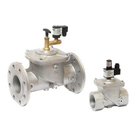
Elektrogas
Elektrogas EVRM-NA User manual

Elektrogas
Elektrogas EVRM-NC User manual
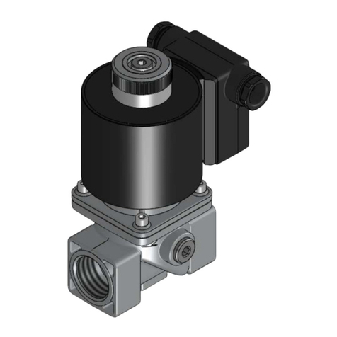
Elektrogas
Elektrogas VMRNA User manual

Elektrogas
Elektrogas VMM User manual
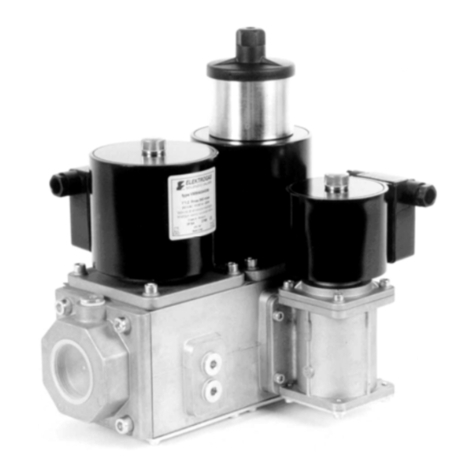
Elektrogas
Elektrogas VMM User manual
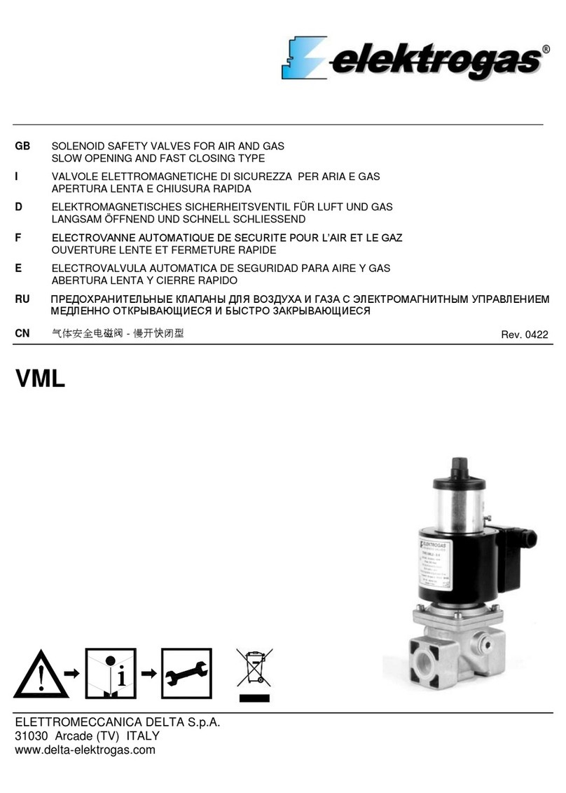
Elektrogas
Elektrogas VML0 User manual
Elektrogas
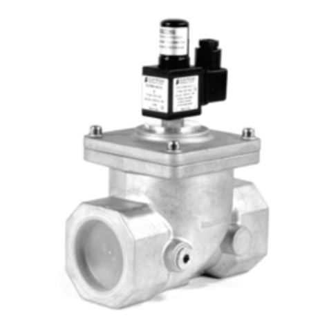
Elektrogas EVRM-NA Series User manual
Elektrogas
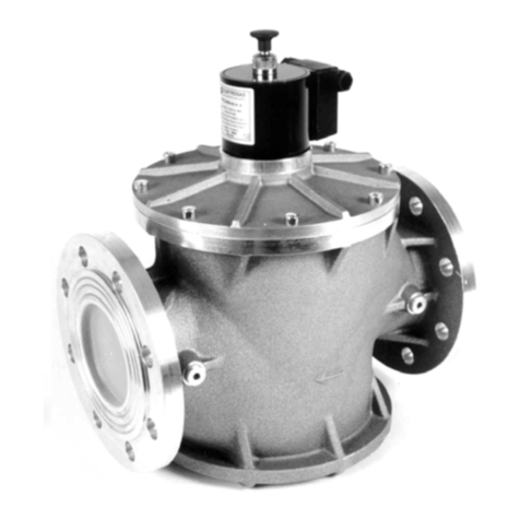
Elektrogas EVRM-NC User manual
Elektrogas
Elektrogas VMR01OTN User manual
