manuals.online logo
Brands
  1. Home
  2. •
  3. Brands
  4. •
  5. Elektrogas
  6. •
  7. Control Unit
  8. •
  9. Elektrogas VMRNA User manual

Elektrogas VMRNA User manual

VMRNA
GB
AUTOMATIC VENT VALVE FOR GAS
NORMALLY OPEN
The VMRNA type is an automatic vent valve for gas appliances (EN 16304).
It is suitable for discharging excess or leakage gas into relief lines.
IT
VALVOLA DI SCARICO AUTOMATICA PER GAS
NORMALMENTE APERTA
La valvola VMRNA è una valvola di scarico automatica per applicazioni che usano gas combustibile (EN 16304).
E’ idonea per rilasciare gas in eccesso o perdite in condotte di scarico.
1-INSTALLATION (Qualified technicians only and in compliance with the rules in force)
Shut off the gas supply and electrical power before servicing any part of the system.
Check correspondence of flow direction with arrow printed on valve body, check correct alignment of connecting
pipes and allow enough space from the walls to allow free air circulation. Connect the outlet of the valve to a vent
line. Avoid overtightening and use proper tools only. We recommend installing a filter upstream of each installation
(d< 1mm). Valve may be mounted with coil in horizontal or vertical position. Coil may be oriented 360 degrees in
any direction. Install in an area that is protected from rain and water splashes or drops.
1- INSTALLAZIONE (Solo personale qulificato ed in accordo con norme/leggi in vigore nel luogo
d’installazione)
Chiudere il gas a monte e spegnere l’alimentazione elettrica prima di eseguire qualsiasi manutenzione
sull’impianto.
Verificare la corrispondenza tra il flusso nella tuibazione e la freccia sul corpo valvola, verificare il corretto
allineamento delle tubazioni e lasciare abbastanza spazio intorno per permettere la libera circolazione dell’aria.
Collegare l’uscita della valvola ad una condotta di scarico. Usare attrezzi idonei ed evitare serraggi eccessivi. Si
raccomanda di installare un filtro all’inizio di ogni linea (passaggio<1mm). La valvola può essere installata con la
bobina in posizione orizzontale o verticale. La bobina può essere ruotata di 360°. Installare in un’area protetta da
pioggia o gocciolamenti.
2- ELECTRICAL CONNECTION (IEC 730-1)
Remove protection cover and connect power cables to rectifier circuit terminal board. Respect printed symbols.
When reassemble use cable gland properly. Should cables pass through originally closed opening, use the rubber
capsule placed underneath the cap to close any other opening.
Perform leak and functional tests after mounting.
2- CABLAGGIO ELETTRICO (IEC 730-1)
Rimuovere il coperchio della scatola di connessione e cablare i cavi al circuito di controllo. Rispettare i simboli
stampati. Usare adeguatamente il pressacavo. Se il cavo viene passato attraverso il foro originariamente chiuso,
verificare che l’altro foro sia chiuso.
Fare un test di tenuta e funzionale dopo l’assemblaggio.
3- CLEANING AND MAINTENANCE (Once per year)
Dust and any foreign bodies may be easily removed from the filter or the gas passage zone. After shutting off
upstream gas and electric current, remove the coil and unscrew the screws fixing the upper flange to the valve
body. During this operation care should be taken not to cause damage to the sealing lip and the sliding rings.
Recommended service life: 10 years.
3- PULIZIA E MANUTENZIONE (Almeno una volta l’anno)
Dopo aver chiuso il gas a monte e spento l’alimentazione elettrica, svitare il cappuccino e sfilare la bobina,
svitare le viti che fissano il coperchio al corpo. Polvere ed altro sporco possono essere rimossi togliendo il filtro,
durante questa operazione attenzione a non danneggiare la sede di tenuta. Rimontare in senso inverso.
Vita utile raccomandata: 10 anni dalla data stampata in etichetta.
Rev. 0618
4- INSTALLATION OF OPEN POSITION SWITCH (optional)
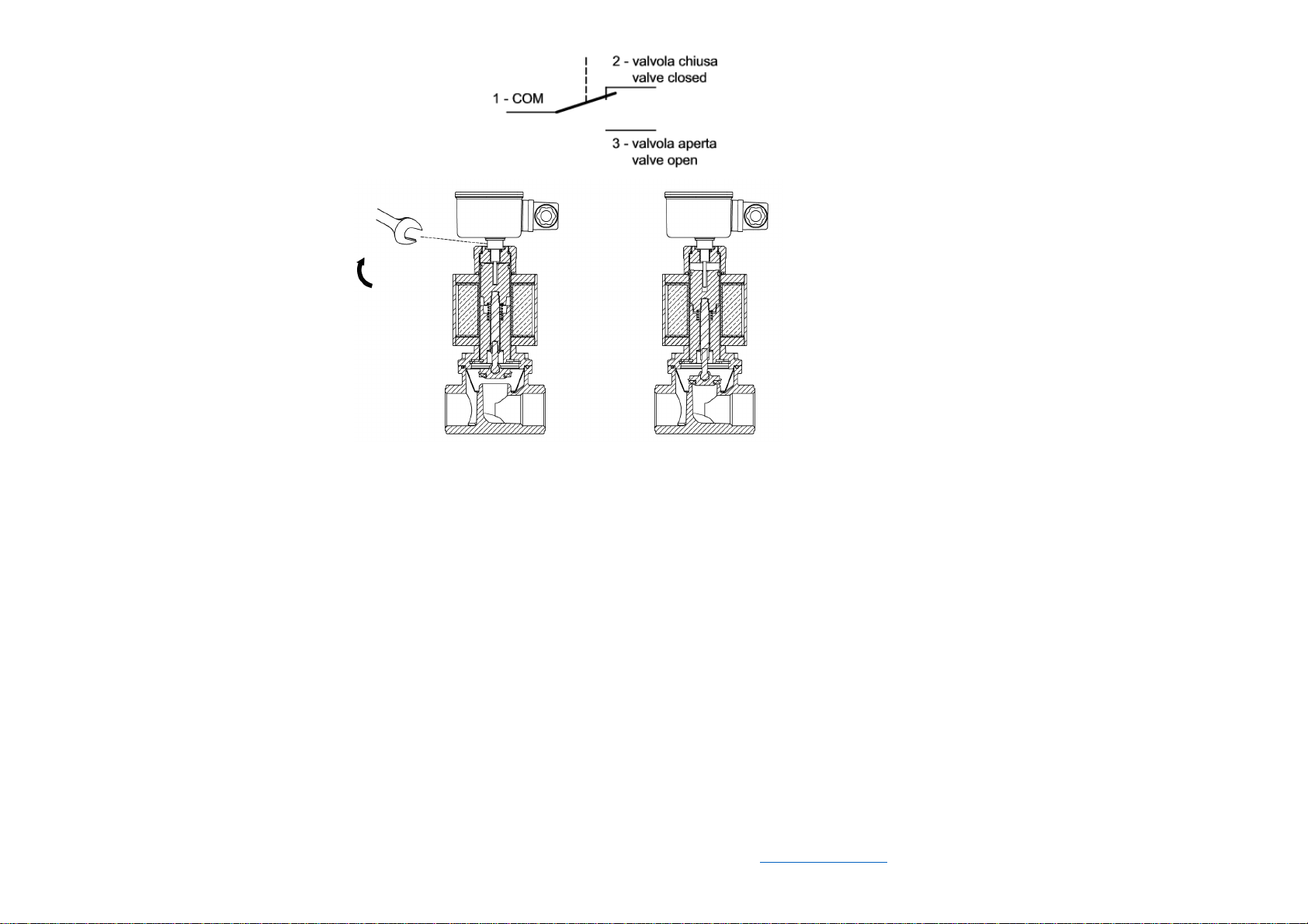
It is possible to install a switch as an open position indicator:
-shutoff gas upstream the valve
-unscrew the plug on the bottom of the valve
-screw the PCS switch
-cable as fig.1
-set the PCS (see PCS instruction)
-close/open the valve to check the correct working of switch
4- INSTALLAZIONE DELL’INDICATORE DI POSIZIONE APERTA PCSRA (optional)
E’ possibile installare un deviatore come indicatore di posizione aperta:
-chiudere il gas a monte della valvola
-svitare il tappo sopra la valvola
-avvitare il PCSRA acquistato separatamente
-cablare i cavi come da fig. a lato
-regolare il PCS (vedi istruzioni PCS)
-chiudere/aprire la valvola per controllare il corretto funzionamento del deviatore
In case of coil replacement:
-unscrew the PCS switch,
-unscrew the coil cap,
-remove the coil
-insert the new coil on the stem
-reassemble all parts in inverse sequence.
In caso di sostituzione della bobina:
-svitare il PCS,
-svitare il cappuccino che fissa la bobina,
-sfialre la bobina
-inserire la nuova bobina
-rimontare le parti in senso inverso e cablare la nuova bobina.
4- TECHNICAL SPECIFICATIONS
Connections Gas threaded ISO 7-1 Rp3/4 or Rp1
or ANSI-ASME B1.20 NPT¾” or NPT1”
Voltage rating and Max operating pressure 230VAC - 110VAC – 24V
200mbar - 500mbar - 6bar (See valve label)
Voltage tolerance -15% / +10%
Ambient temperature -15°C / +60°C
Flow (Air- ∆p=1mbar) 8 m
3
/h
Mechanical group 2
Overal dimension 77x140x88
Weight 1.4 Kg
Opening and closing time < 1 second
Protection class (EN 60529) IP54 (optional IP65 with cable)
Cable glands (EN 50262) M20x1,5 for cable Ø8/10
(PG9-cable Ø6/8 or PG11 cable Ø7/9 for ISO4400 plug)
Pressure inlets G1/4 on two sides (except models integrated in VMM)
Strainer 600 µm (only 200 and 500mbar model)
Gas type (EN 437) Air and non-aggressive gases 1, 2 and 3 (gaseous state only)
(special version for aggressive gases e.g. biogas)
ATEX INSTALLATION: Special conditions for safe use (X)
1) Ambient temperature -15°C/+40°C; 2) Low mechani cal danger; 3) Clean with a mist cloth;
4) Do not disconnect the plug when energized; 5) Ensure an external grounding of the valve housing.
4- SPECIFICHE TECNICHE
Connessioni Filetto gas ISO 7-1 Rp3/4 o Rp1
oppure filetto ANSI-ASMEB1.20 NPT3/4” o NPT1”
Tensione di funzionamento e massima pressione funzionamento 230VAC - 110VAC – 24V
200mbar - 500mbar - 6bar (vedi targa dati)
Tolleranza sulla tensione -15% / +10%
Temperatura ambiente -15°C / +60°C
Portata (Aria- ∆p=1mbar) 8 m
3
/h
Gruppo di resistenza meccanica 2
Ingombri 77x140x88
Peso 1.4 Kg
Tempo di aperture e chiusura < 1 secondo
Grado di protezione scatola connessione EN 60529 - IP54 (optional IP65 con cavo)
Pressacavi (EN 50262) M20x1,5 per cavi Ø8/10
(in caso di connettore ISO 4400 PG9-cavo Ø6/8 o PG11 cavo Ø7/9)
Prese pressione G1/4 in ingresso su entrambi I lati (tranne modello integrato su VMM)
Filtro 600 µm (solo modelli 200 e 500 mbar)
Tipo di gas (EN 437) Aria e gas non aggressive famiglie 1, 2 e 3 (solo in stato gassoso)
(versione speciale per biogas)
INSTALLAZIONE ATEX: Condizioni speciali per un utilizzzo sicuro (X)
1) Temperatura ambiente -15°C/+40°C; 2) Rischio me ccanico basso; 3) Pulire con un panno umido;
4) Non scollegare il connettore sotto tensione; 5) Prevedere una messa a terra esterna del corpo valvola
.
Elektrogas si riserva la facoltà di apportare aggiornamenti o modifiche tecniche senza preavviso. Elektrogas si riserva la facoltà di apportare aggiornamenti o modifiche tecniche senza preavviso.
ELETTROMECCANICA DELTA S.p.A. - 31030 Arcade (TV) ITALY - www.delta-elektrogas.com

Other Elektrogas Control Unit manuals

Elektrogas VMH DN Series User manual

Elektrogas

Elektrogas VMH DN Series User manual

Elektrogas EVRM-NA User manual

Elektrogas

Elektrogas EVRM-NA User manual

Elektrogas VMR Series User manual

Elektrogas

Elektrogas VMR Series User manual

Elektrogas VMM User manual

Elektrogas

Elektrogas VMM User manual

Elektrogas VML Series User manual

Elektrogas

Elektrogas VML Series User manual

Elektrogas VMM User manual

Elektrogas

Elektrogas VMM User manual

Elektrogas EVRM-NC User manual

Elektrogas

Elektrogas EVRM-NC User manual

Elektrogas VMRNA User manual

Elektrogas

Elektrogas VMRNA User manual

Elektrogas VML2 User manual

Elektrogas

Elektrogas VML2 User manual

Elektrogas VMR01OTN User manual

Elektrogas

Elektrogas VMR01OTN User manual

Elektrogas EVRM-NA User manual

Elektrogas

Elektrogas EVRM-NA User manual

Elektrogas VML0 User manual

Elektrogas

Elektrogas VML0 User manual

Elektrogas EVRM-NC User manual

Elektrogas

Elektrogas EVRM-NC User manual

Elektrogas EVRM-NA Series User manual

Elektrogas

Elektrogas EVRM-NA Series User manual

Elektrogas EVRM-NA User manual

Elektrogas

Elektrogas EVRM-NA User manual

Popular Control Unit manuals by other brands

Gemu eSyDrive R649 operating instructions

Gemu

Gemu eSyDrive R649 operating instructions

BENDIX TC-7 TRAILER CONTROL BRAKE VALVE manual

BENDIX

BENDIX TC-7 TRAILER CONTROL BRAKE VALVE manual

Haldex PR installation guide

Haldex

Haldex PR installation guide

jbc NAU instruction manual

jbc

jbc NAU instruction manual

Siemens RMZ78 Series manual

Siemens

Siemens RMZ78 Series manual

Conrad 191083 operating instructions

Conrad

Conrad 191083 operating instructions

Swagelok 60 Series instructions

Swagelok

Swagelok 60 Series instructions

Philips GreenPower LED series Application guide

Philips

Philips GreenPower LED series Application guide

Spirax Sarco 25P Installation and maintenance instructions

Spirax Sarco

Spirax Sarco 25P Installation and maintenance instructions

Bastl Knit Rider manual

Bastl

Bastl Knit Rider manual

Thermotron 8200 Plus instruction manual

Thermotron

Thermotron 8200 Plus instruction manual

Tabor Electronics Preliminary Lucid-X Series user manual

Tabor Electronics

Tabor Electronics Preliminary Lucid-X Series user manual

PIMORONI Picade PIM430 quick start guide

PIMORONI

PIMORONI Picade PIM430 quick start guide

Allmatic ARGO 1 Series manual

Allmatic

Allmatic ARGO 1 Series manual

Digital Equipment Pro-face GP-377R Series user manual

Digital Equipment

Digital Equipment Pro-face GP-377R Series user manual

Emerson CASH VALVE FRM Installation, Maintenance, and Parts Manual

Emerson

Emerson CASH VALVE FRM Installation, Maintenance, and Parts Manual

KSB ISORIA 10 Installation & operating manual

KSB

KSB ISORIA 10 Installation & operating manual

Task Force Tips ER Bubble Cup Instructions for installation, safe operation and maintenance

Task Force Tips

Task Force Tips ER Bubble Cup Instructions for installation, safe operation and maintenance

manuals.online logo
manuals.online logoBrands
  • About & Mission
  • Contact us
  • Privacy Policy
  • Terms and Conditions

Copyright 2025 Manuals.Online. All Rights Reserved.