manuals.online logo
Brands
  1. Home
  2. •
  3. Brands
  4. •
  5. Elko
  6. •
  7. Switch
  8. •
  9. Elko CRM-42 User manual

Elko CRM-42 User manual

1 / 2
CRM-42
CRM-42F
cos φ ≥ 0.95 M M HAL.230V
KM M
AC12
x
DC14
x
AC1
250V / 16A
AC13
x
AC2
250V / 5A
AC14
250V / 6A
AC3
250V / 3A
AC15
250V / 6A
AC5b
1000W
DC5
24V / 2A
AC6a
x
DC12
24V / 6A
AC7b
250V / 3A
DC13
24V / 2A
02-90/2016 Rev.: 0
DC1
24V / 10A
DC3
24V / 3A
1
3
5
6
2
4
17
18S A2
A1
A1 18
A2 S
N
L
A1 18
A2 S
N
L
a b c
ELKO EP, s.r.o.
Palackého 493
769 01 Holešov, Všetuly
Czech Republic
Tel.: +420 573 514 211
e-mail: [email protected]
www.elkoep.com
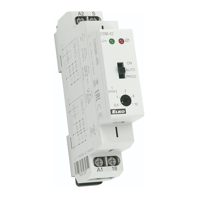
Programmable staircase switch
- CRM-42 with signalling before switch o
- CRM-42F without signaling
• intelligent staircase switch, the same use as CRM-4, but with enlarged possibility of control
in mode „PROG“ it is possible to select time of delayed OFF by number of button pressing.
Each pressing multiplies time set by potentiometer, it means that in case you set time to
5 min and press the button 3 times, then the output is automatically prolonged to 15 min.
Output can be also switched o before time (reset) by long pressing of button (longer than
2 sec).
• output relay contact 16 A/AC1 with inrush current up to 80 A enables switching of el. bulbs
and also uorescent lights
• operating system switch:
ON - output is constantly ON (service model)
AUTO - timing according to adjusting by potentiometer in range 30 s - 10 min
PROG - timing with time prolongation option by number button pressing
• timing (in mode AUTO and PROG) is possible to be stopped by long pressing of the button
(> 2 s)
• voltage range: AC 230 V, clamp terminals
• output indication: multif. red LED, ashing at certain states
• 3-wire or 4-wire connection (it is possible to control input S by potential A1 or A2)
• CRM-42: warning before switch OFF- output doubleash 40 and 30 sec before switch
OFF
• CRM-42F: without doubleash product particularly suitable for energy-saving light bulbs,
where frequent swit ching is due to damage
• function unti-block button protection (e.g. against blocking by a match)
• 1- MODULE, DIN rail mounting
Characteristics
Description
Symbol
Connection
Type of load
Mat. contacts AgSnO2,
contact 16A
Type of load
Mat. contacts AgSnO2,
contact 16A
AC5a
uncompensated
230V / 3A (690VA)
AC5a
compensated
230V / 3A (690VA)
to max. input C=14uF
EN
1. Supply terminal
2. Controlling input
3. Supply indication
4. Output indication
5. Function setting
6. Time delay setting 0.5 s -10 min
7. Output contact
Operating switch
a) Operating switch in ON position = permanent switch ON of relay contacts. This position
is used for cleaning up, service and faults discovery around the load.
b) In this position is device set in operating state and operates according to diagramm and
adjusted time.
c) Timing with the possibility of the illumination lenght extention by pressing a button
(max. extention is 30 min).
3-wire connection
4-wire connection
2 / 2
CRM-42 CRM-42F
CRM-42,
CRM-42F
CRM-42F
CRM-42
CRM-42F
CRM-42
U
S
18
LED
400ms
U
S
18
LED
2s
tt
U
S
18
LED
2stt
U
S
18
LED
>2s
tt t t t t
U
S
18
LED
>2s
tt t t t t
Warning
Technical parameters
Device is constructed for connection in 1-phase AC 230 V main alternating current voltage
and must be installed according to norms valid in the state of application. Connection
according to the details in this direction. Installation, connection, setting and servicing
should be installed by qualied electrician sta only, who has learnt these instruction
and functions of the device. This device contains protection against overvoltage peaks
and disturbancies in supply. For correct function of the protection of this device there
must be suitable protections of higher degree (A, B, C) installed in front of them. According
to standards elimination of disturbancies must be ensured. Before installation the main
switch must be in position “OFF”and the device should be de-energized. Don´t install the
device to sources of excessive electro-magnetic interference. By correct installation ensure
ideal air circulation so in case of permanent operation and higher ambient temperature
the maximal operating temperature of the device is not exceeded. For installation and
setting use screw-driver cca 2 mm. The device is fully-electronic - installation should be
carried out according to this fact. Non-problematic function depends also on the way of
transportation, storing and handling. In case of any signs of destruction, deformation, non-
function or missing part, don´t install and claim at your seller it is possible to dismount the
device after its lifetime, recycle, or store in protective dump.
Function
Function:
Supply terminals:
Supply voltage:
Consumption:
Supply voltage tolerance:
Supply indication:
Time ranges:
Time setting:
Time deviation:
Repeat accuracy:
Temperature coecient:
Output
Number of contacts:
Current rating:
Breaking capacity:
Inrush current:
Switching voltage:
Output indication:
Mechanical life:
Electrical life (AC1):
Electrical life (AC5b):
Control
Control voltage:
Power the control input:
Glow tubes connetions:
Max. amount of glow lamps
connected to controlling
input:
Control. terminals:
Impulse length:
Reset time:
Other information
Operating temperature:
Storage temperature:
Operating position:
Mounting:
Protection degree:
Overvoltage cathegory:
Pollution degree:
Max. cable size (mm2):
Dimensions:
Weight:
Standards:
delay OFF responsive to control contact switch on
A1 - A2
AC 230 V / 50 - 60 Hz
AC max. 12 VA / 1.8 W
-15 %; +10 %
green LED
0.5 - 10 min
potentiometer
5 % - mechanical setting
5 % - set value stability
0.05 % / °C, at = 20 °C (0.05 % / °F, at = 68 °F)
1x NO - SPST (AgSnO2), switches potencial A1
16 A / AC1
4000 VA / AC1, 384 W / DC
30 A / < 3 s
250 V AC1 / 24 V DC
red LED
3x10⁷
0.7x10⁵
8x10⁴(bulbs 1000 W) *
AC 230 V
AC 0.53 VA
Yes
230 V - max. amount 50 pcs
(measured with glow lamp 0.68 mA / 230 V AC)
A1-S or A2-S
min. 50 ms / max. unlimited
max. 150 ms
-20 °C to +55 °C (-4 °F to 131 °F)
-30 °C to +70 °C (-22 °F to 158 °F)
any
DIN rail EN 60715
IP40 from front panel / IP10 terminals
III.
2
solid wire max. 2x 2.5 or 1x 4 /
with sleeve max. 1x 2.5 or 2x 1.5, (AWG 12)
90 x 17.6 x 64 mm (3.5˝ x 0.7˝ x 2.5˝)
65 g (2.3 oz.)
EN 60669-2-3, EN 61010-1
* For bigger bulb dimmers and frequent switching w recommend to strengthen relay
contact by power contactor, for example by a contactor line VSxxx.
switch to ON
Mode ON - the output is permanently closed in ON position. Control input is blocked.
Mode AUTO - by pressing a control button in function AUTO the output closes and after
the set time period the output opens.
CRM-42: Warning before switch OFF - output doubleash 40 and 30 sec before switch OFF. *
CRM-42F: without ashing.
Mode PROG (the illumination time is dened by number of button pressing) - in function
program the switched time is a sum of each time set by pressing the button. By pressing
> 2 s the ouput opens.
CRM-42: Warning before switch OFF - output doubleash 40 and 30 sec before switch OFF. *
CRM-42F: without ashing.
* If the total set time is less than 1 min, there is no ashing according to the graph of the
function.
Other manuals for CRM-42

2

This manual suits for next models

1

Other Elko Switch manuals

Elko SHT-7 User manual

Elko

Elko SHT-7 User manual

Elko DIM-2 User manual

Elko

Elko DIM-2 User manual

Elko HRH-5 User manual

Elko

Elko HRH-5 User manual

Elko CRM-42 User manual

Elko

Elko CRM-42 User manual

Elko iNELS RFJA-12B User manual

Elko

Elko iNELS RFJA-12B User manual

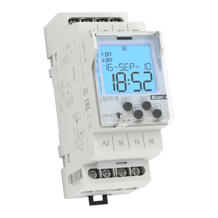
Elko SHT-6 User manual

Elko

Elko SHT-6 User manual

Elko inels RFSA-61M/MI/230V User manual

Elko

Elko inels RFSA-61M/MI/230V User manual

Elko iNels RFSAI-61B User manual

Elko

Elko iNels RFSAI-61B User manual

Elko SOU-3 User manual

Elko

Elko SOU-3 User manual

Elko SOU-3 User manual

Elko

Elko SOU-3 User manual

Elko iNels RFSA-61M User manual

Elko

Elko iNels RFSA-61M User manual

Elko inels RFSOU-1 User manual

Elko

Elko inels RFSOU-1 User manual

Elko SOU-2 User manual

Elko

Elko SOU-2 User manual

Elko iNels RFSAI-62B User manual

Elko

Elko iNels RFSAI-62B User manual

Elko EKO07115 User manual

Elko

Elko EKO07115 User manual

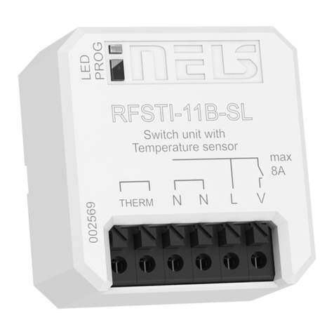
Elko RFSTI-11B-SL User manual

Elko

Elko RFSTI-11B-SL User manual

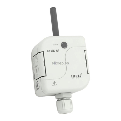
Elko inels RFUS-61 User manual

Elko

Elko inels RFUS-61 User manual

Elko SHT-6 User manual

Elko

Elko SHT-6 User manual

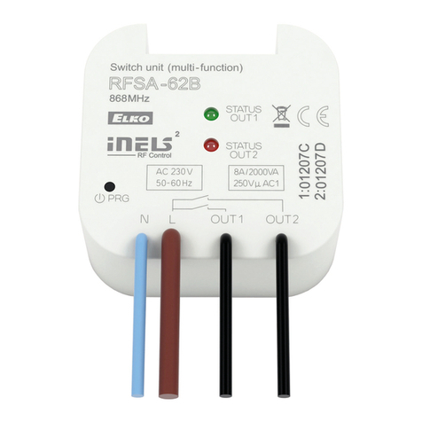
Elko RFSA-62B User manual

Elko

Elko RFSA-62B User manual

Elko RFWB-20/G User manual

Elko

Elko RFWB-20/G User manual

Elko iNels RFSOU-1 User manual

Elko

Elko iNels RFSOU-1 User manual

Elko RFJA-12B/230V User manual

Elko

Elko RFJA-12B/230V User manual

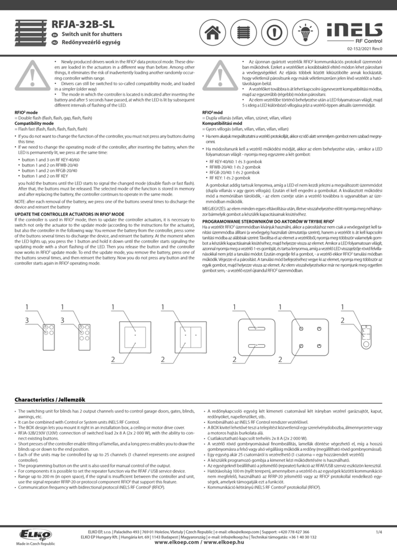
Elko iNels RFJA-32B-SL User manual

Elko

Elko iNels RFJA-32B-SL User manual

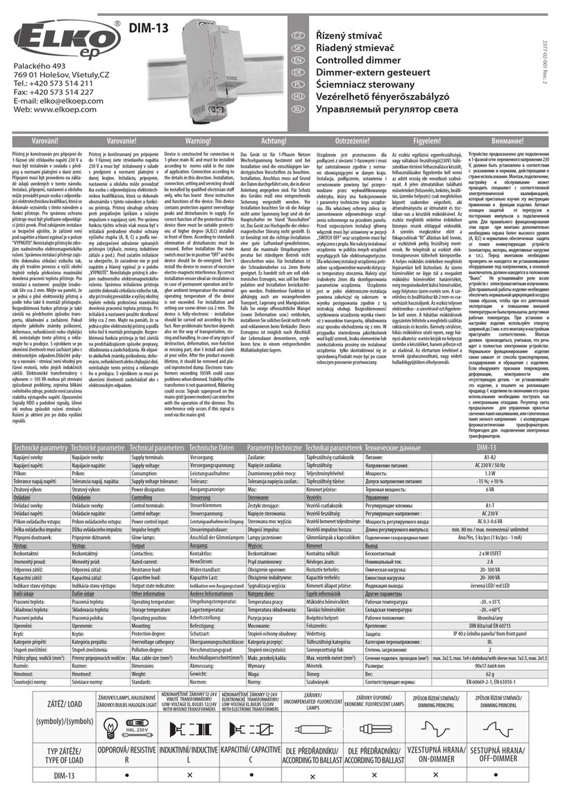
Elko DIM-13 User manual

Elko

Elko DIM-13 User manual

Popular Switch manuals by other brands

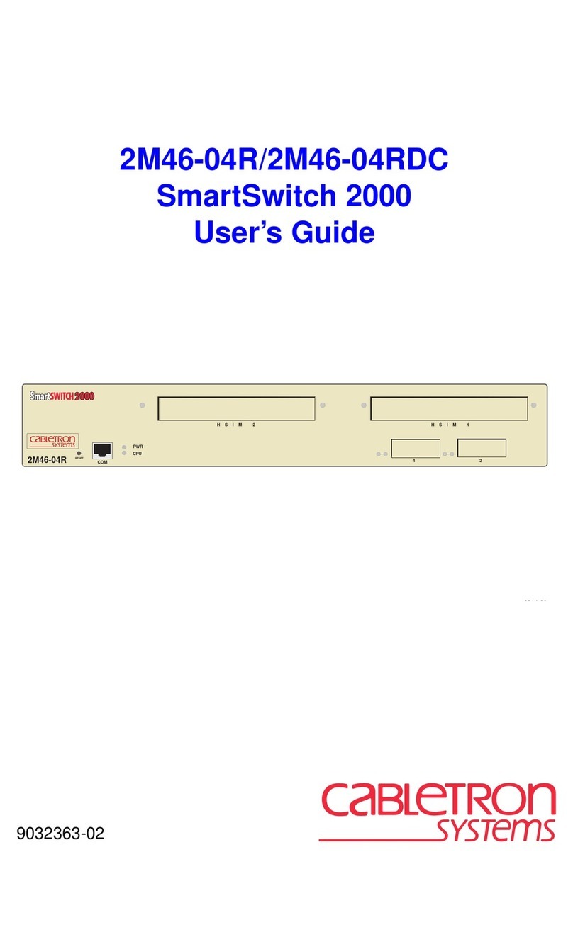
Cabletron Systems pmn user guide

Cabletron Systems

Cabletron Systems pmn user guide

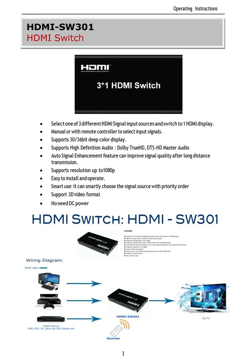
Jlinks HDMI-SW301 operating instructions

Jlinks

Jlinks HDMI-SW301 operating instructions

NEO NEXUS SWITCH 24 user manual

NEO

NEO NEXUS SWITCH 24 user manual

LEGRAND 672 63 manual

LEGRAND

LEGRAND 672 63 manual

iPuray BRT-319 manual

iPuray

iPuray BRT-319 manual

SIIG USB Over IP user manual

SIIG

SIIG USB Over IP user manual

horiba X-52 Operation manual

horiba

horiba X-52 Operation manual

Arista 7020SR-32C2 Series quick start guide

Arista

Arista 7020SR-32C2 Series quick start guide

Eaton Edison Cooper Power Series Installation and operation instructions

Eaton

Eaton Edison Cooper Power Series Installation and operation instructions

Comtech EF Data Radyne RCS20 Installation and operation manual

Comtech EF Data

Comtech EF Data Radyne RCS20 Installation and operation manual

Primewire 302630 user manual

Primewire

Primewire 302630 user manual

IOGear MiniView SE GCS82B quick start guide

IOGear

IOGear MiniView SE GCS82B quick start guide

HP 480-0005-00-15 Product guide

HP

HP 480-0005-00-15 Product guide

BAZOO USB HUB user manual

BAZOO

BAZOO USB HUB user manual

LEGRAND adorne sofTap Dimmer ADTP600RMH installation instructions

LEGRAND

LEGRAND adorne sofTap Dimmer ADTP600RMH installation instructions

NoiseKen ESS-B3011 instruction manual

NoiseKen

NoiseKen ESS-B3011 instruction manual

SANRAD I3.1.1205 user manual

SANRAD

SANRAD I3.1.1205 user manual

TP-Link JetStream T1600G-52TS user guide

TP-Link

TP-Link JetStream T1600G-52TS user guide

manuals.online logo
manuals.online logoBrands
  • About & Mission
  • Contact us
  • Privacy Policy
  • Terms and Conditions

Copyright 2025 Manuals.Online. All Rights Reserved.