Elkron P440 User manual
Other Elkron Security System manuals

Elkron
Elkron TM24-A User manual
Elkron
Elkron MP 200 User manual
Elkron
Elkron HP600 Assembly instructions

Elkron
Elkron wl31 User manual
Elkron
Elkron HP375M User manual
Elkron
Elkron HP201 User manual
Elkron
Elkron HP602L User manual
Elkron
Elkron CR200 GPRS Assembly instructions

Elkron
Elkron FM500 User manual
Elkron
Elkron EL20 Series User manual

Elkron
Elkron DC200 User manual
Elkron
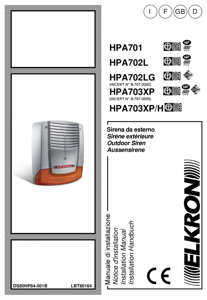
Elkron HPA701 User manual
Elkron
Elkron HP30WL User manual
Elkron
Elkron CR200 GPRS Assembly instructions
Elkron
Elkron HPA700M User manual
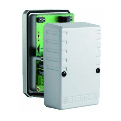
Elkron
Elkron MS04 User manual

Elkron
Elkron TM24I User manual
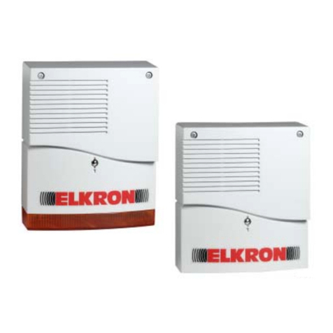
Elkron
Elkron HP501 User manual

Elkron
Elkron KP500D/N User manual

Elkron
Elkron HPA800 User manual
Popular Security System manuals by other brands

Secure
Secure USAB-1 operating instructions

B&B
B&B 480 SERIES Operation & maintenance manual

ADEMCO
ADEMCO VISTA-20P Series Installation and setup guide

Inner Range
Inner Range Concept 2000 user manual

Johnson Controls
Johnson Controls PENN Connected PC10 Install and Commissioning Guide

Aeotec
Aeotec Siren Gen5 quick start guide
