The PerformanceAlert™ Gateway System Overview • 1
1 Overview
The PerformanceAlert™ Gateway is designed to allow
the Emerson Climate Technologies Retails Solutions fam-
ily of site controllers (E2, Einstein, and REFLECS) to in-
terface directly with up to 14 Copeland®
PerformanceAlert™ Diagnostic Modules.
The Gateway uses two network ports: one, a MODBUS
port used to connect the Gateway with the Perfor-
manceAlert™ modules, and the second an I/O network port
that connects the Gateway to the I/O network of an E2 or
Einstein control system (or COM A/D of a REFLECS net-
work).
The Gateway mimics the behavior of a MultiFlex 16 in-
put board, passing along data from the PerformanceAlert™
modules about compressor behavior to the site controller in
the form of virtual board/point addresses. The Gateway’s
board/point addresses may be used by the site controller for
I/O control, logging, and alarming.
1.1. The PerformanceAlert™
Gateway System
A typical layout of a CPC-controlled Perfor-
manceAlert™ network configuration is shown in Figure 1-
1. Each compressor in each rack is equipped with one Per-
formanceAlert™ Diagnostic Module. All modules are
wired together in a single MODBUS daisy-chain and con-
nected to the PerformanceAlert™ Gateway board. The
Gateway Board is also connected to the E2 via the I/O net-
work, where it mimics the behavior of a MultiFlex input
board (16AI) and sends values from the modules to the E2
as virtual board/point addresses.
1.2. The PerformanceAlert™
Gateway Board
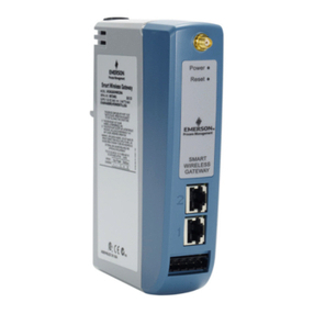
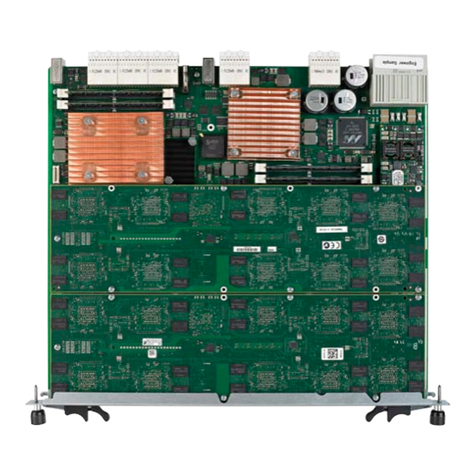
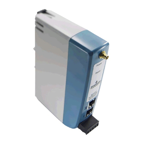
The PerformanceAlert™ Gateway (Figure 1-2) allows
you to connect up to fourteen (14) PerformanceAlert™ Di-
agnostic Modules. On the I/O network, the Gateway board
mimics the behavior of one or more 16AI boards, which
use virtual 16AI board/point addresses to pass along infor-
mation from the modules to the E2.
The PerformanceAlert™ Gateway is capable of operat-
ing in one of two different modes: a Condensed Mode,
which maps a single 16AI point to the alarm status of each
PerformanceAlert™ module, and an Expanded Mode,
which maps sixteen 16AI points for each module, includ-
ing alarm status for all alarm types, current transducer val-
ues, and discharge line temperature.
In Condensed Mode, the PerformanceAlert™ Gateway
mimics the equivalent of one 16AI board. In Expanded
Mode, the PerformanceAlert™ Gateway mimics the equiv-
alent of up to fourteen 16AI boards.
1.3. The PerformanceAlert™
Diagnostic Module
The Copeland®PerformanceAlert™ Diagnostic Mod-
ule is a breakthrough innovation for troubleshooting refrig-
eration system faults. The module can be installed in the
electrical box of the condensing unit near the compressor
contactor or in the electrical panel of a refrigeration rack
system. By monitoring and analyzing data from the Cope-
land®brand compressors, the module can accurately detect
the cause of electrical and system related issues.
Figure 1-1 - Typical Layout of PerformanceAlert™ Modules and
Gateway Board
Figure 1-2 - Gateway Board
LEGEND
1
2
3
4
5
6
8
9
7
Hand-Held Terminal Jack
RS485 I/O Network
RS485 Receiver Bus Net
I/O Net Term Jumpers
1
2
3
4
5
68
9
7
Receiver Bus Term Jumpers
General Status LED
Alarm Status LED
Dip Switch
Power Connector
26502044
10
11
10
11
I/O Net Status LED
Receiver Bus Status LED
