Enelion Vertica User manual

Enelion
Vertica
22 kW
Installation
manual
for the specialists
ver. 1.6
© Enelion 05.2017


General notes
At various points in this manual you will see notes and precautionary warnings
regarding possible hazards. The symbols used have the following meanings:
Technical Specications
Two charging panels: socket / cable (depends on version),
3x400V AC ~ 50Hz,
22kW (32A) for one charging panel,
3P+N+PE,
Standby power - 4W for one charging panel.
WARNING!
Indicates a potentially hazardous situation which, if not avoided,
could result in death or serious injury.
CAUTION!
Indicates a potentially hazardous situation which, if not avoided,
may result in minor or moderate injury.
ATTENTION!
Indicates a situation which, if not avoided could result
in property damage.
ESD
This symbol reminds you of the possible consequences of
touching electrostatically sensitive components.
Notice
Notes on use of equipment and useful practical tips are identied
by “i”. Notices do not contain any information that draws
attention to potentially dangerous or harmful functions.
Additional important information.
Enelion VERTICA
Installation manual ver. 1.6, © Enelion 05.2017 1

1 Important information
1.1 Safety instructions
WARNING!
Not observing the safety
instructions can result in risk
of death, injuries and damage
to the device! ENELION LTD assumes no
liability for claims resulting from this!
Electrical hazard!
The installation, commissioning and
maintenance of the charging station may only
be performed by correctly trained, qualied
and authorized electricians who are fully
responsible for the compliance with existing
standards and installation regulations.
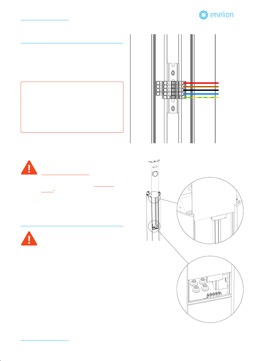
Only supply the terminals from 3 phases 400V with
grounded sources!
Before commissioning, check all screw and terminal
connections for rm seating!
The connector panel cover may never be left open
unattended. Mount the connector panel cover if you
leave the charging station.
Use of the charging station with open cable insertion
openings is prohibited.
Do not carry out any unauthorized conversion work
or modications to the charging station!
Repair work to the charging station is not permitted
and may only be performed by the manufacturer
(replacement of the charging station)!
Do not remove any notices on the device, such as
safety symbols, warning notices, rating plates,
nameplates or cable markings!
Observe the instructions given for selecting the
location and the constructional requirements!
If the specications for the location are not
observed, this can result in death, serious physical
injury or equipment damage if the corresponding
precautionary measures are not met!
Pull the charging cable only at the plug and not at
the cable out of the connector.
Ensure that the charging cable is not mechanically
damaged (bent, pinched or run over) and the
connection area does not come into contact with
heat sources, dirt or water.
5 safety rules:
- Shut down all poles and all sides!
- Secure against reactivation!
- Check that the equipment is voltage-free!
- Ground and short-circuit!
- Cover adjacent live parts and restrict
access to hazardous areas!
Installation manual ver. 1.6, © Enelion 05.2017
Important information
2

ATTENTION!
Risk of damage!
Make sure that the charging station is not damaged
by improper handling (anchoring, housing cover,
socket, inner parts etc.).
Do not open the lid of terminal in the rain!
Risk of damage the aluminium and plexi housing!
- Use only detergents dedicated for anodised
aluminium / plexi,
- Do not tighten the mounting screws with force.
1.2 Intended use
NOTICE
Enelion Vertica is a charging terminal for outdoor
area at which electrically operated vehicles can be
charged.
Two vehicles can be charged at the same time, with 3
phases, 32A and maximum 22kW power.
The charging station is designed for installation on
a pavement mounted column.
The respective national regulations must be
observed with regard to the installation and
connection of the charging terminal.
The intended use of the device always includes the
compliance with the environmental conditions for
which this device was developed.
The device was developed, manufactured, inspected
and documented in compliance with the relevant
safety standards. Therefore, the products do not
pose any danger to the health of persons or a risk
of damage to other property or equipment under
normal circumstances, provided that the instructions
and safety precautions relating to the intended use
are properly observed.
The instructions contained in this manual must be
followed precisely in all circumstances.
Failure to do so could result in the creation of
potential sources of danger or the disabling of safety
devices. Apart from the safety instructions given
in this manual, the safety precautions and accident
prevention measures appropriate to the situation in
question must also be observed.
Only electrical vehicles or their chargers may be
connected. A connection of other loads (e.g. electric
tools) is not permitted!
Electrostatically sensitive
components
Information for technicians who are permitted to
open the device:
Risk of damage!
Electronic components can be destroyed if touched!
Before handling components, make sure you
perform an electrical discharge by touching
a metallic, grounded object!
Enelion VERTICA
Installation manual ver. 1.6, © Enelion 05.2017
Important information
3

g.1
16
7
32
14
13
8
12
17
5
4
5
3
10
9
11
21
27
30
33
33
33
6
22829
1
31
22
18
20
25
PART NO.
PART
DESCRIPTION
QUANTITY
1
Housing Profile Alu
4
2
Ground Plate
1
3
Front Panel
1
4
Socket Core
1
5
Socket Cover With Flap
1
6
B18.3.1M - 6 x 1.0 x 16 Hex SHCS
-- 16SHX
14
7
Top Cover Plate
1
8
Upper Structural Rib
1
9
Structural Rib - Connector
1
10
Wago Connector Male
2
11
B18.22M - Plain washer, 6 mm,
regular
4
12
B18.3.6M - M5 x 0.8 x 10 Hex
Socket Cone Pt. SS --S
4
13
Center Element
1
14
B18.2.4.1M - Hex nut, Style 1,
M6 x 1 --D-S
2
15
B18.2.4.1M - Hex nut, Style 1,
M3 x 0.5 --D-S
4
16
M5 Security Screw
2
17
Motherboard
1
18
LCD
1
19
RFID
1
20
Pilot Box
1
21
Wago Connector Female
1
22
Distance Screw Hex M3x8
8
23
Distance Screw Hex M2.5x8
3
24
Distance Screw Hex M2.5x20
3
25
Computer with gsm (optional)
1
26
DIN Rail
1
27
Connector Mount
1
28
Lower Alu Plate
1
29
Lower Panel
1
30
DIN Rail - Short
1
31
Pilot RP Mount v2
1
32
Top Gasket
1
33
Wago Connection Terminal
1
16
7
32
14
13
8
12
17
5
4
5
3
10
9
11
21
27
30
33
33
33
6
22829
1
31
22
18
20
25
PART NO.
PART
DESCRIPTION
QUANTITY
1
Housing Profile Alu
4
2
Ground Plate
1
3
Front Panel
1
4
Socket Core
1
5
Socket Cover With Flap
1
6
B18.3.1M - 6 x 1.0 x 16 Hex SHCS
-- 16SHX
14
7
Top Cover Plate
1
8
Upper Structural Rib
1
9
Structural Rib - Connector
1
10
Wago Connector Male
2
11
B18.22M - Plain washer, 6 mm,
regular
4
12
B18.3.6M - M5 x 0.8 x 10 Hex
Socket Cone Pt. SS --S
4
13
Center Element
1
14
B18.2.4.1M - Hex nut, Style 1,
M6 x 1 --D-S
2
15
B18.2.4.1M - Hex nut, Style 1,
M3 x 0.5 --D-S
4
16
M5 Security Screw
2
17
Motherboard
1
18
LCD
1
19
RFID
1
20
Pilot Box
1
21
Wago Connector Female
1
22
Distance Screw Hex M3x8
8
23
Distance Screw Hex M2.5x8
3
24
Distance Screw Hex M2.5x20
3
25
Computer with gsm (optional)
1
26
DIN Rail
1
27
Connector Mount
1
28
Lower Alu Plate
1
29
Lower Panel
1
30
DIN Rail - Short
1
31
Pilot RP Mount v2
1
32
Top Gasket
1
33
Wago Connection Terminal
1
Installation manual ver. 1.6, © Enelion 05.20174

1
3
2
4
1
2
2
2
3
3
3
3
3
3
3
3
3
3
3
3
3
3
3
4
44
50
500
NO.
PART QUANTITY
1
Basis Plate(bottom)/
Leveling Plate (top)
2
2
Threaded Rod M12
4
3
Nut M12
16
4
Washer M12
4
1 Installation guidelines
1.1 Before Installing
This document describes how to install Enelion
Vertica charging station.
Before any installation work is performed, study all
drawings furnished by the supplier for the particular
installation.
1.2 Safety Requirements
Ensure that at all times when working,
no power is connected.
• Eye protection with appropriate glasses
(especially when using the electrical drill).
• In the installation be sure to not connect directly
to power distribution network cables without
additional protection.
• Use appropriate tools for each function.
1.3 Delivery content – packages
Charging station is delivered to a client in separate
packages containing:
• Case – steel construction with attached alumin-
ium proles, connection for 3x400V (3P+N+PE)
and top cover with two security screws - g.2
• Two panels with electric elements, electronics
and a socket or a charging cable (depends on
a charger’s version) - g.3
• Foundation preparation kit (if ordered) - g.4
• Set of screws for panels installation, a key for
security screws, 2 RFID cards, 2 RFID key holders.
Upon receipt of shipment, examine the
package for damage. If the shipping
container must be opened outdoors,
take proper precautions to prevent the
entrance of moisture.
g.3
g.4
g.2
Enelion VERTICA
Installation manual ver. 1.6, © Enelion 05.2017
Installation guidelines
5

1.4 Installation Overview
Before installation check local requirements for
3-phase electric device contact (terminal) and policy
of electric devices installation in public spaces.
Terminal installation steps:
• prepare a foundation for terminal,
• mount a terminal case to the base,
• connect terminal to the power grid,
• install charging panels,
• close terminal.
1.5 Installation
1. Terminal base preparation with
Foundation Preparation Kit
• Terminal Foundation Kit (id ordered) contains
four threaded rods, 16 M12 screws, and 4 gaskets
and 2 basis plates g.5.
• Mount to bottom basket four rods and tight the
nuts onto. Repeat steps with top basket. On the
top should be left 50mm rods free space g.6.
• Insert mounted construction and cable conduit
(not included) into concrete. Cable conduit
should be guided via one of top basket hole g .7.
Level position of top basket with screws
under the plate. Screws should touch te
concrete. Use M12 wrench.
• after concrete solidify, remove top base.
Ensure that at all times when working,
no power is connected.
g.5
g.6
g.7
1
3
2
4
1
2
2
2
3
3
3
3
3
3
3
3
3
3
3
3
3
3
3
4
44
50
500
NO.
PART
QUANTITY
1
Basis Plate(bottom)/
Leveling Plate (top)
2
2
Threaded Rod M12
4
3
Nut M12
16
4
Washer M12
4
1
3
2
4
1
2
2
2
3
3
3
3
3
3
3
3
3
3
3
3
3
3
3
4
44
50
500
NO.
PART
QUANTITY
1
Basis Plate(bottom)/
Leveling Plate (top)
2
2
Threaded Rod M12
4
3
Nut M12
16
4
Washer M12
4
1
3
2
4
1
2
2
2
3
3
3
3
3
3
3
3
3
3
3
3
3
3
3
4
44
50
500
NO.
PART
QUANTITY
1
Basis Plate(bottom)/
Leveling Plate (top)
2
2
Threaded Rod M12
4
3
Nut M12
16
4
Washer M12
4
Installation manual ver. 1.6, © Enelion 05.2017
Installation guidelines
6

2. Mounting terminal case to the base
• Before installation pull up plexi panels from
both sides of the case bottom, to get access to
the inside installation area and to the contact
(terminal)
• Install the terminal case on the prepared
foundation g.8,9
• After installing the case, tightly screw the nuts on
ø12 rods g.10.
• Do not put the bottom plexi panels yet.
g.8
g.9
g.10
1
3
2
4
1
2
2
2
3
3
3
3
3
3
3
3
3
3
3
3
3
3
3
4
44
50
500
NO.
PART
QUANTITY
1
Basis Plate(bottom)/
Leveling Plate (top)
2
2
Threaded Rod M12
4
3
Nut M12
16
4
Washer M12
4
1
3
2
4
1
2
2
2
3
3
3
3
3
3
3
3
3
3
3
3
3
3
3
4
44
50
500
NO.
PART
QUANTITY
1
Basis Plate(bottom)/
Leveling Plate (top)
2
2
Threaded Rod M12
4
3
Nut M12
16
4
Washer M12
4
1
3
2
4
1
2
2
2
3
3
3
3
3
3
3
3
3
3
3
3
3
3
3
4
44
50
500
NO.
PART
QUANTITY
1
Basis Plate(bottom)/
Leveling Plate (top)
2
2
Threaded Rod M12
4
3
Nut M12
16
4
Washer M12
4
Enelion VERTICA
Installation manual ver. 1.6, © Enelion 05.2017
Installation guidelines
7

3. Connection to the power grid
In the lower (bottom) part of the terminal there is
a contact to the powergrid, which divides electric
energy to two charging panels at the same time.
• Pull out black plexi panel to get access to the
contact.
• Connect wires from the contact to the
socket - g.11
Terminal must be earthed. Ensure, that
yellow-and-green wire is connected to the
working earhting contact!
Ensure, that wires to power grid have
proper diameter. It must be minimum
16mm2.
• Insert (slide in) black plexi panels on each side of
the case.
4. Charging panels installation
Charging panels have a safe connection
system with the powegrid through
a contact with a socket and a plug.
• Before installing a charging panel, make sure that
a fuse and RCD are turned on (working)
• Lift the panel and slide it in the rails of an alumin-
ium prole g.12. If there are any difculties in
sliding the panel in, put a drop of a thick grease
into each rail.
• At the end of the sliding in, a plug on the panel will
get inside the socket in the case - g.13.
• On the top, screw two screws to the case - g.20.
• Repeat all above with the second charging panel.
The installation, commissioning and
maintenance of the charging station may only
be performed by correctly trained, qualied
and authorized electricians who are fully
responsible for the compliance with existing
standards and installation regulations.
Ensure that at all times when working,
no power is connected.
g.11
phase 3
phase 2
phase1
neutral
earth
g.13
g.12
Installation manual ver. 1.6, © Enelion 05.2017
Installation guidelines
8

4. Connection to internet
To connect to the internet, use the GSM SIM card.
SIM card must be without PIN number.
Card slot is located in hole at back wall of charging
panel g.14.
• Unlock slot g.15,
• Open slot g.16,
• Insert SIM card with goldenpins
faced to pins on GSM module g .17.
• Close slot - g 18.
• Lock slot - g 19. g.14
g.15 g.16
g.17
g.18 g.19
Enelion VERTICA
Installation manual ver. 1.6, © Enelion 05.2017
Installation guidelines
9

5. Closing the terminal
• Put a lid on the top and screw two security
screws to the case - g.21.
g.20
g.12
g.21
Installation manual ver. 1.6, © Enelion 05.2017
Installation guidelines
10

1.6 First start
Turn the power on in the power grid supply.
On the screens you will see a welcoming
message.After connection with internet,
terminal is ready to use.
Please note: charger has list of current
APN adresses and passwords to connect
with mobile Internet Provider. If there is
new provider, installer nedds to update
memory card inside charger (please
contact with Enelion specialist).
1.7 Online conguration
Online charger works with Enelion Administration
Software or with third parts software via OCPP 1.6.
In Enelion Admin Software you can:
• To add to map and remotely manage charger.
• To add users and assign RFID cards.
• To make tariff plans to sell energy to users.
• To congure static and dynamic load balancing.
To enable Enelion Admin Software please contact us:
info@enelion.com
Enelion VERTICA
Installation manual ver. 1.6, © Enelion 05.2017
Installation guidelines
11

www.enelion.com
Other manuals for Vertica
4
Table of contents
Other Enelion Batteries Charger manuals

Enelion
Enelion LUMINA User manual

Enelion
Enelion Wallbox User manual

Enelion
Enelion Stilo User manual

Enelion
Enelion LUMINA User manual

Enelion
Enelion Stilo User manual

Enelion
Enelion Vertica User manual

Enelion
Enelion Vertica User manual

Enelion
Enelion Wallbox User manual

Enelion
Enelion LUMINA User manual

Enelion
Enelion Stilo User manual