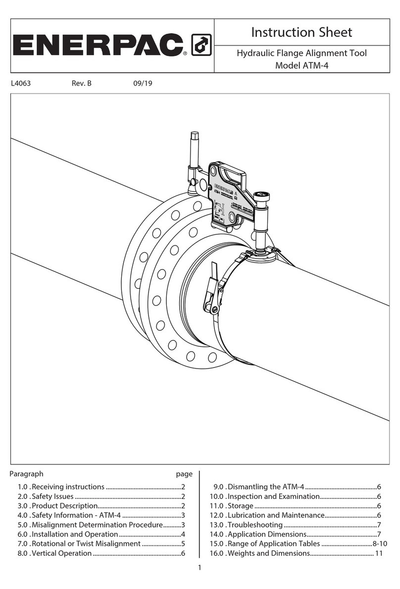
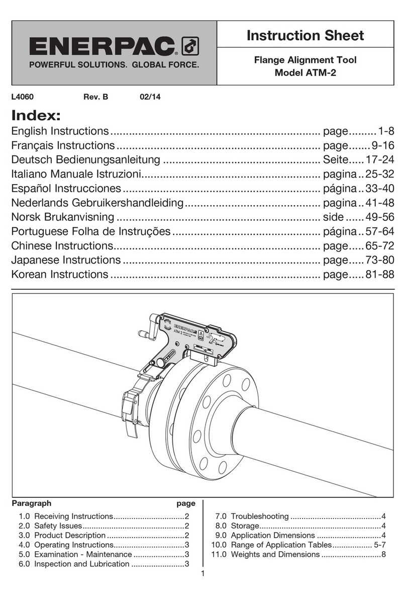
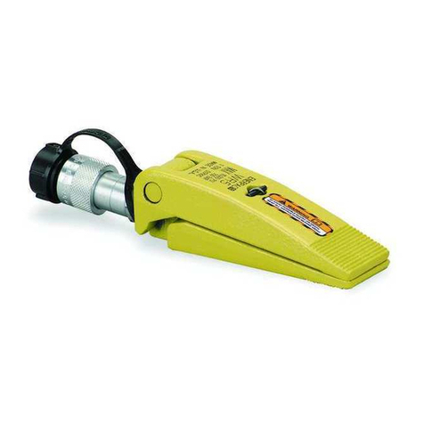
Enerpac ATM-9 User manual

1
L4065 Rev. C 09/19
Instruction Sheet
Hydraulic Flange Alignment Tool
Model ATM-9
For other languages go to www.enerpac.com.
Weitere Sprachen finden Sie unter www.enerpac.com.
Para otros idiomas visite www.enerpac.com.
Pour toutes les autres langues, rendez-vous sur www.
enerpac.com.
Per altre lingue visitate il sito www.enerpac.com.
その他の言語は
www.enerpac.com
でご覧いただけます。
이 지침 시트의 다른 언어 버전은
www.enerpac.com.
Ga voor de overige talen naar www.enerpac.com.
For alle andre språk henviser vi til www.enerpac.com.
Para outros idiomas consulte www.enerpac.com.
如需其他语言,请前往 www.enerpac.com.
Paragraph page
1.0 Receiving Instructions................2
2.0 Safety Issues.......................2
3.0 Product Description .................2
4.0 Safety Information ..................3
5.0 List of Equipment ...................3
6.0 Misalignment Determination ...........3
7.0 Installation and Operation.............4
8.0 Rotational or Twist Misalignment .......5
9.0 Dismantling the ATM-9 ...............5
10.0 Inspection and Examination..........6
11.0 Storage..........................6
12.0 Lubrication and Maintenance.........6
13.0 Troubleshooting ...................7
14.0 Air Lock Removal ..................7
15.0 Minimum / Maximum Extension.......7
16.0 Application Range .................7
17.0 Range of Application Tables ....... 8-10
18.0 Weights and Dimensions ........... 11

2
1.0 RECEIVING INSTRUCTIONS
Visually inspect all components for shipping damage.
Shipping damage is not covered by warranty. If
shipping damage is found notify carrier at once. The
carrier is responsible for all repair and replacement
costs resulting from damage in shipment.
safety first
Read all instructions, warnings and cautions carefully.
Follow all safety precautions to avoid personal injury
or property damage during system operation. Enerpac
cannot be responsible for damage or injury resulting
from unsafe product use, lack of maintenance or
incorrect product and/or system operation. Contact
Enerpac when in doubt as to the safety precautions
and applications. To protect your warranty, use only
ENERPAC hydraulic oil.
A CAUTION is used to indicate correct operating or
maintenance procedures and practices to prevent
damage to, or destruction of equipment or other
property
A WARNING indicates a potential danger that requires
correct procedures or practices to avoid personal
injury.
2.0 SAFETY ISSUES
Failure to comply with the
following cautions and warnings
could cause equipment damage
and personal injury.
IMPORTANT: Minimum age of the operator
must be 18 years. The operator must have
read and understood all instructions, safety
issues, cautions and warnings before starting to operate
the Enerpac equipment. The operator is responsible for
this activity towards other persons.
WARNING: To avoid personal injury and
possible equipment damage, make sure all
hydraulic components withstand the
maximum pressure of 10,000 psi [700 bar].
IMPORTANT: Minimize the risk of
overloading. Use hydraulic gauges in each
hydraulic system to indicate safe operating
loads. It is your window to what is happening in the
system.
WARNING: Do not overload equipment.
Overloading causes equipment failure and
possible personal injury.
CAUTION: Make sure that all system
components are protected from external
sources of damage, such as excessive heat,
flame, moving machine parts, sharp edges and
corrosive chemicals.
CAUTION: Avoid sharp bends and kinks
that will cause severe back-up pressure in
hoses. Bends and kinks lead to premature
hose failure.
WARNING: Immediately replace worn or
damaged parts with genuine Enerpac parts.
Enerpac parts are designed to fit properly
and withstand rated loads.
WARNING: Always wear safety glasses. The
operator must take precaution against injury
due to failure of the tool or workpiece
DANGER: Do not handle pressurized hoses.
Escaping oil under pressure can penetrate
the skin, causing serious injury. If oil is
injected under the skin, see a doctor immediately.
WARNING: Never pressurize uncoupled
couplers. Only use hydraulic equipment in a
coupled system.
IMPORTANT: DO NOT lift hydraulic
equipment by the hoses or couplers. Use
the carrying handle or other means of safe
transport.
We recommend the use of special loosening
liquids or sprays. Enerpac hydraulic torque
wrenches offer both square and hexagon
drive units to loosen or tighten bolts and nuts. Enerpac
offers nut splitters in case a nut can not be removed.
3.0 PRODUCT DESCRIPTION
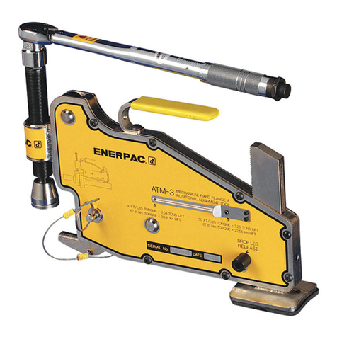
The ATM-9 Alignment Tool is intended for use in typical
maintenance and installation procedures. It allows the
realignment of misaligned flanges within a 9 Ton [90 kN]
physical capacity. For example,it may be used to assist
in the replacement of ring and other type joints.
The ATM-9is a hydraulically operated tool actuated
by a hydraulic cylinder and hand pump. The maximum
operating pressure is 10,000 psi [700 bar].
The use of these instructions will promote the safe use
and maximum service life of the tool. All sections of this
instruction sheet should be read prior to using the tool.

3
3.1 Major Features and Components
Fig. 1
Drop Leg
Hydraulic
Cylinder
P-142 Hydraulic Pump
Hydraulic
Hose
ATM-9
Tool
Strap
3.2 Technical Data
Tool Description: Aligning Force:
Hydraulic fixed flange
and rotational alignment
tool.
9.0 T [90 kN]
from 10,000 psi [700 bar]
of hydraulic pressure.
Note: Refer to section 18.0 for weights and dimensions.
4.0 SAFETY INFORMATION
IMPORTANT: In all installations the site safety
requirements must be adhered to. The safety of the
operator and any assisting personnel is of paramount
importance along with the safety of others including the
general public.
These instructions are intended only to cover the safe
operation of ATM-9during a normal maintenance and
installation operation. All other safety aspects must be
controlled by the operation supervisor.
CAUTION: The ATM-9must not be attached
to pressure vessel nozzles.
WARNING: Never attach the ATM-9 to a
joint until after the flange bolts have been
loosened and removed. Overloading may
occur if bolts are removed while the tool is installed,
and the resulting force is greater than the safe working
load of the tool.
5.0 LIST OF EQUIPMENT
The tool set includes:
• ATM-9 alignment tool with hydraulic cylinder.
• Hydraulic hose, 6 feet [1,8 m] long.
•P-142 hydraulic hand pump.
• 3/8 inch NPTF couplers on hose, cylinder and pump.
• Ratchet and strap.
• Instruction sheet.
• Carrying case.
Note: All hydraulic components are rated for 10,000
psi [700 bar] operation.
6.0 MISALIGNMENT DETERMINATION
PROCEDURE
• The ATM-9must not be attached to a flanged joint
prior to the misalignment determination procedure
being carried out.
Refer to warning statement in
section 4.0.
• Every second bolt should be loosened and removed.
Continue with this procedure. Misalignment may
not occur until only a few bolts remain. At this point
the direction of any misalignment should become
obvious.
• The ATM-9, once attached, will directly push against
the misalignment,bringing the joint back into
alignment.
Example: Misalignment in various directions
A flanged joint, once broken down, may spring out of
alignment at any point, or in any direction around.
See Fig. 2. The ATM-9should be attached at the
maximum point of misalignment i.e. A or B. Each
example shows where ATM-9should be attached.
Fig. 2

7.0 INSTALLATION AND OPERATION
1. Determine the maximum points of misalignment.
(see Fig.3). The maximum points are on the top or
bottom of the joint, as illustrated by the arrows.
Point of Max.
Misalignment
Point of Max.
Misalignment
Fig. 3
2. Guide the lift hook of the tool into the bolt hole at the
maximum point of misalignment. Then, adjust the
drop leg down onto the pipe by turning the adjusting
knob in the clockwise direction (see Fig.4).
Fig. 4
Lift Hook
Adjusting
Knob
Drop
Leg
Note: The tool should be held up level within the bolt
hole during adjustment. The tool must remain parallel to
the pipe at all times.
3. Pull out the lock pin and extend the wing out to the
desired distance (see Fig.5). Rotate the cylinder
clockwise until it locates onto the surface of the
opposite flange. At this stage,ensure that the tool is
sitting level and that the end of the cylinder is in full
contact with the surface of the higher flange.
4. Attach the hook of the strap through one of the slots
on the buckle (located above the drop leg pad).
Place the hook of the ratchet through the other slot
on the opposite side of the buckle. Feed the end
of the strap through the ratchet and tighten. (see
Fig.6).
Fig. 5
Hydraulic
Cylinder Wing
Wing Lock Pin
Fig. 6
Ratchet
Strap
Buckle
5. Connect the P-142 hydraulic pump to the hydraulic
hose, and the hose to the hydraulic cylinder. Operate
the pump handle until the joint comes into alignment.
(see Fig.7).
Fig. 7
Hydraulic
Hand Pump
Hydraulic
Hose
Note: The ATM-9 hydraulic cylinder is rated at 10,000
psi [700 bar] operating pressure. The P-142 hydraulic
pump contains a built-in safety relief valve that opens
at approximately 10,500 psi [724 bar].
WARNING: If a different pump is used in
place of the P-142 for any reason, be certain
that the pump relief valve is not set higher
than 10,500 psi [724 bar]. Install a pressure gauge in
the circuit to monitor system pressure.
4

5
6. When alignment is completed, the flange bolts may
be inserted and tightened. After replacing all of the
bolts in all open bolt holes (except for the bolt hole in
which the tool lift hook is inserted), remove the tool
by reversing steps 1 through 5.
CAUTION: Open pump release valve and be
sure that all hydraulic pressure is relieved
before disconnecting any hoses or fittings.
7. After removing the tool from the flange, insert and
tighten the last flange bolt in the remaining bolt hole.
8.0 ROTATIONAL OR TWIST MISALIGNMENT
This is a common problem on both onshore and
offshore pipeline installations (see Fig. 8). Quite often
the flanges are in alignment but the operator is unable
to fit the bolt into any two corresponding bolt holes on
the joint‘s circumference. The ATM-9, with its 90 kN [9
ton] capacity, has the ability to manipulate the flanges
in various directions.
The set-up procedure is the same as before with one
possible exception. The ATM-9can be attached to
the most accessible point on the joint‘s circumference
because the misalignment occurs at all bolt holes to the
same degree.
8.1 The recommended operating procedures are:
1. Select the most convenient or accessible point on
the joint‘s circumference and attach the tool there.
(Follow steps 1 thru 5 in section 7.0).
2. In the situation when both flanges are aligned but
rotational misalignment is present the ATM-9is used
to push the flanges beyond alignment until one pair
of bolt holes become parallel (see point A in Fig. 8).
Fig. 8
A
3. Insert the bolt into the bolt hole at point A and
then release ATM-9. The load will transfer onto the
inserted bolt.
4. The ATM-9can then be attached at another point on
the joint‘s circumference (see Fig. 9) pushing against
the inserted bolt. Advance the hydraulic cylinder until
another, or all the bolt holes are parallel (see Fig. 10).
5. Once the remaining bolts are inserted, the ATM-9
can be removed.
Fig. 9
A
Fig. 10
Please note that in some situations the operator may
have to ‘chase’ the misalignment around the joint‘s
circumference and attach the ATM-9at several different
positions to rectify the misalignment. On each occasion
the procedures outlined in steps 1 to 7in section 7.0
should be followed.
9.0 DISMANTLING THE ATM-9
• Once alignment is achieved, all work on the joint
finished, and bolt-up completed (apart from the bolt
hole in which the ATM-9is located), the tool can be
removed from the joint by reversing steps 1 thru 5in
section 7.0.
• Care should be taken not to drop any of the
component parts when removing them from the
aligned joint. This action will prevent injuries
personnel.
Note: Refer to the ATM-9 repair parts sheet for
complete parts list and assembly diagrams.

6
10.0 INSPECTION AND EXAMINATION
• After finishing the job and before the ATM-9 is
placed back into service, the completeness of the
tool must be established and items examined to
ensure that they are serviceable.
• Any missing or damaged items are to be replaced
as soon as possible and prior to the tool being
used again.
• Grease all moving parts regularly. Refer to section
12.0, Lubrication and Maintenance.
• Cap or plug all open hydraulic fittings to prevent
dirt entry. Be sure that pump air vent cap is in the
“closed” position.
• Ensure rollers and pins remain grit free.
• Return all items to the carrying case when not in
use.
11.0 STORAGE
• Cap or plug all open hydraulic fittings.
• Smear machined surfaces with grease.
• Store the ATM-9in a cool dry place.
12.0 LUBRICATION AND MAINTENANCE
Use Mobilgrease XHP ™ 222 Special grease or an
equivalent
good quality high load bearing grease
.
Always ensure that the wing of the tool is grit-free and
that the rollers rotate freely and are well lubricated (see
Fig. 13). This will enhance the tool’s performance and
help prolong its service life.
Clean, inspect and lubricate the ATM-9 as described in
the following steps:
STEP 1. Place tool flat on work bench.
STEP 2. Remove two spring pins on the front of the
main body
(see Fig. 11)
.
STEP 3. Pull the wing lock pin out. Remove the
wing from the main body by sliding it
forward
(see Fig. 12)
.
STEP 4. Remove the circlips using a circlip pliers
(see Fig. 13).
STEP 5. Slide the roller shafts out in order to remove
the rollers and bearings for examination.
(see Fig. 13).
STEP 6.
Inspect the roller shafts, rollers and bearings
for damage, If there is no damage present,
then these parts can be cleaned, greased and
reassembled (reverse steps 1 through 5).
Fig. 11
Spring Pins
Wing
Fig. 12
Wing Lock Pin
1. Rollers and Bearings
2. Circlips
3. Roller Shafts
1
1
2
2
3
2
2
3
Fig. 13

7
13.0 TROUBLESHOOTING
Problem 1:
The hydraulic cylinder is sliding on the circumference of
the opposite flange as the ATM-9is aligning the joint.
Cause:
Grit or dirt on wing, rollers or bearings, wing is at full
extension.
Solution:
A. Ensure the rollers are rotating freely and that there is
no restriction to the rollers on the wing surfaces such
as dirt or grit.
B. Check that the wing is not at full extension when
aligning the joint.
C. Ensure that there is enough extension left to allow
the ATM-9to expand as the joint is aligned.
Problem 2:
The ATM-9is attached and appears to be functioning
properly, but the joint will not align.
Cause:
A. There may be air in the hydraulic system restricting
the force on the flanges.
B. There may be something restricting the joint at a
point close to the flanges. The joint may require more
than 9 ton [90 kN]pressure to align.
Solution:
A. See air lock removal instructions in section 14.
B. Check the area around the joint to establish if there
is an obstruction to the joint.
C. If the joint requires more force than that of the 9ton
[90 kN] capacity of the tool,then another method to
align the joint should be adopted.
14.0 AIR LOCK REMOVAL
Remove air as described in the following steps:
1. Remove the air vent cap on top of the hydraulic
pump and check hydraulic oil level to ensure there is
enough oil to advance the cylinder.
2. Replace air vent cap, but do not tighten the cap.
The cap must remain loose (in the “vent” position) to
allow air to enter and leave the pump during use. The
cap should only be tightened fully when the tool is to
be returned to the carrying case after use.
3. With the air vent cap loose, connect the pump to
the tool with the hydraulic hose supplied within the
carrying case.
4. Stand the tool on a level surface, hold the hydraulic
pump above the tool, close the release valve on the
pump, and prime the pump to advance the hydraulic
cylinder until the cylinder is fully advanced and a
small pressure is achieved.
5. With the hydraulic pump held above the tool, open
the release valve allowing the cylinder to retract fully
back. While the cylinder is retracting any air that is
within the system will be forced up to the pump and
vented out through the air vent cap.
6. Repeat the above procedure three or four times to
ensure that all air is removed and the tool will reach
full working pressure.
15.0 MINIMUM / MAXIMUM EXTENSION
Refer to section 18.0, Weights and Dimensions,for
minimum and maximum extension information.
16.0 APPLICATION RANGE
Two basic dimensions, A and B, will determine if the
ATM-9 can be used to align the joint. If the flange joint
to be aligned is between 3.66 inch [93 mm] and 9 inch
[228 mm] as illustrated by (A), has a bolt hole size of
1.40 inch [35,5 mm] or greater (B),then the ATM-9can
be attached and alignment achieved (see fig. 14).
See charts in section 17: by flange type, class and
diameter.
Fig. 14 – Min. and max. flange sizes (visual)
Min. bolt hole size
1.40 inch [35,5 mm]
Min. distance 3.66 inch [93 mm]
Max. distance 9 inch [228 mm]
Hook into this
bolt hole
Saddle of hydraulic
cylinder must rest fully on
the circumference of the
flange to be pushed.
A
B

17.0 RANGE OF APPLICATION TABLES
CLASS A
NPS 3
1/2" 4" 5" 6" 7" 8" 9" 10" 12" 13" 14" 15" 16" 17" 18" 19" 20" 21" 22" 23" 24" 26" 27" 29" 30" 33" 35" 36" 39" 42" 45" 48" 54" 60" 66" 72"
TOOL ATM-2 ATM-2
ATM-2
ATM-4 ATM-4
CLASS D
NPS 4" 5" 6" 7" 8" 9" 10" 12" 13" 14" 15" 16" 17" 18" 19" 20" 21" 22" 23" 24" 29" 30" 33" 35" 36" 39" 42" 45" 48" 54" 60" 66" 72" 78" 84" 96" 108" 120"
TOOL ATM-2 ATM-4 ATM-9
CLASS E
NPS 1
1/4"
1
1/2" 2" 2
1/2" 3" 3
1/2" 4" 5" 6" 7" 8" 9" 10" 12" 13" 14" 15" 16" 17" 18" 19" 20" 21" 22" 23" 24" 27" 29" 30" 33" 35" 36" 39" 42" 45" 48"
TOOL ATM-2 ATM-4 ATM-9
CLASS F
NPS 1
1/4"
1
1/2" 2" 2
1/2" 3" 3
1/2" 4" 5" 6" 7" 8" 9" 10" 12" 13" 14" 15" 16" 17" 18" 19" 20" 21" 22" 23" 24" 27" 29" 30" 33" 35" 36" 39" 42" 45" 48"
TOOL ATM-2 ATM-4 ATM-9
CLASS H
NPS 1
1/4"
1
1/2" 2" 2
1/2" 3" 3
1/2" 4" 5" 6" 7" 8" 9" 10" 12" 13" 14" 15" 16" 17" 18" 19" 20" 21" 22" 23" 24"
TOOL ATM-2 ATM-4
CLASS J
NPS 1
1/4"
1
1/2" 2" 2
1/2" 3" 3
1/2" 4" 5" 6" 7" 8" 9" 10" 12" 13" 14" 15" 16" 17" 18" 19" 20" 21" 22" 23" 24"
TOOL ATM-2 ATM-4 ATM-9
CLASS K
NPS 1" 1
1/4"
1
1/2" 2" 2
1/2" 3" 3
1/2" 4" 5" 6" 7" 8" 9" 10" 12" 13" 14" 15" 16" 17" 18" 19" 20"
TOOL ATM-2 ATM-4 ATM-9
CLASS R
NPS 1" 1
1/4"
1
1/2" 2" 2
1/2" 3" 3
1/2" 4" 5" 6" 7" 8" 9" 10" 12" 13" 14" 15" 16" 17" 18" 19" 20"
TOOL ATM-2 ATM-4 ATM-9
CLASS S
NPS 1/2" 3/4" 1" 1
1/4"
1
1/2" 2" 2
1/2" 3" 3
1/2" 4" 4
1/2" 5" 6" 7" 8" 9" 10" 11" 12" 13" 14" 15" 16"
TOOL ATM-2 ATM-4 ATM-9
CLASS T
NPS 1/2" 3/4" 1" 1
1/4"
1
1/2" 2" 2
1/2" 3" 3
1/2" 4" 4
1/2" 5" 6" 7" 8" 9" 10" 11" 12" 13"
TOOL ATM-2 ATM-4 ATM-9
CLASS
2K
NPS 1 13-16" 2 1-16" 2 9-16" 3 1-8" 4 1-16" 5 1-8" 7 1-16" 9" 11" 13 5-8" 16 3-4"
TOOL ATM-2 ATM-4 ATM-9
CLASS
3K
NPS 1 13-16" 2 1-16" 2 9-16" 3 1-8" 4 1-16" 5 1-8" 7 1-16" 9" 11" 13 5-8" 16 3-4"
TOOL ATM-2 ATM-4 ATM-9
CLASS
6K
NPS 1 13-16" 2 1-16" 2 9-16" 3 1-8" 4 1-16" 5 1-8" 7 1-16" 9" 11" 13 5-8" 16 3-4"
TOOL ATM-4 ATM-9
CLASS
2K
NPS 2 1-16" 2 9-16" 3 1-8" 4 1-16" 5 1-8" 7 1-16" 9" 11" 13 5-8" 16 3-4" 21 1-4"
TOOL ATM-2 ATM-4
CLASS
3K
NPS 2 1-16" 2 9-16" 3 1-8" 4 1-16" 5 1-8" 7 1-16" 9" 11" 13 5-8" 16 3-4" 21 1-4"
TOOL ATM-2 ATM-4 ATM-9
CLASS
6K
NPS 2 1-16" 2 9-16" 3 1-8" 4 1-16" 5 1-8" 7 1-16" 9" 11" 13 5-8" 16 3-4" 21 1-4"
TOOL ATM-2 ATM-4 ATM-9
BS10 Flange Range of Application
API6BX Weld Neck Flange Range of Application API6B Weld Neck Flange Range of Application
SUITABLE FOR ENERPAC ATM-2 TOOL
SUITABLE FOR ENERPAC ATM-4 TOOL
SUITABLE FOR ENERPAC ATM-9 TOOL
NOT SUITABLE FOR ANY ENERPAC ATM TOOL
Note: Models ATM-2 and ATM-4 shown for reference purposes only.
17.1
17.2 17.3
8

9
CLASS
150
NPS 3/4" 1" 1
1/4"
1
1/2" 2" 2
1/2" 3" 3
1/2" 4" 5" 6" 8" 10" 12" 14" 16" 18" 20" 24"
TOOL ATM-2 ATM-4
CLASS
300
NPS 3/4" 1" 1
1/4"
1
1/2" 2" 2
1/2" 3" 3
1/2" 4" 5" 6" 8" 10" 12" 14" 16" 18" 20" 24"
TOOL ATM-2 ATM-4
CLASS
400
NPS 3/4" 1" 1
1/4"
1
1/2" 2" 2
1/2" 3" 3
1/2" 4" 5" 6" 8" 10" 12" 14" 16" 18" 20" 24"
TOOL ATM-2 ATM-4 ATM-9
CLASS
600
NPS 3/4" 1" 1
1/4"
1
1/2" 2" 2
1/2" 3" 3
1/2" 4" 5" 6" 8" 10" 12" 14" 16" 18" 20" 24"
TOOL ATM-2 ATM-4 ATM-9
CLASS
900
NPS 1/2" 3/4" 1" 1
1/4"
1
1/2" 2" 2
1/2" 3" 4" 5" 6" 8" 10" 12" 14" 16" 18" 20" 24"
TOOL ATM-2 ATM-4 ATM-9
CLASS
1500
NPS 1/2" 3/4" 1" 1
1/4"
1
1/2" 2" 2
1/2" 3" 4" 5" 6" 8" 10" 12" 14" 16" 18" 20" 24"
TOOL ATM-2 ATM-4 ATM-9
CLASS
2500
NPS 1/2" 3/4" 1" 1
1/4"
1
1/2" 2" 2
1/2" 3" 4" 5" 6" 8" 10" 12" 14" 16" 18" 20" 24"
TOOL ATM-2 ATM-4 ATM-9
ASME B16.5 Flange Range of Application
DIN Weld Neck Flange Range of Application
CLASS
150
NPS 22" 26" 28" 30" 32" 34" 36" 38" 40" 42" 44" 46" 48"
TOOL ATM-4 ATM-9
CLASS
300
NPS 22" 26" 28" 30" 32" 34" 36" 38" 40" 42" 44" 46" 48"
TOOL ATM-4 ATM-9
CLASS
400
NPS 22" 26" 28" 30" 32" 34" 36" 38" 40" 42" 44" 46" 48"
TOOL ATM-4 ATM-9
CLASS
600
NPS 22" 26" 28" 30" 32" 34" 36" 38" 40" 42" 44" 46" 48"
TOOL ATM-4 ATM-9
CLASS
900
NPS 22" 26" 28" 30" 32" 34" 36" 38" 40" 42" 44" 46" 48"
TOOL ATM-9
ASME B16.47 Flange Range of Application
CLASS
PN16
NPS 1
1/2" 2" 2
1/2" 3" 4" 5" 6" 7" 8" 10" 12" 14" 16" 18" 20" 24" 28" 32" 36" 40" 48" 56 72" 80"
TOOL ATM-2 ATM-4 ATM-9
CLASS
PN25
NPS 1/2" 3/4" 1" 1
1/4"
1
1/2" 2" 2
1/2" 3" 4" 5" 6" 7" 8" 10" 12" 14" 16" 18" 20" 24" 28" 32" 36" 40"
TOOL ATM-2 ATM-4
CLASS
PN40
NPS 1
1/2" 2" 2
1/2" 3" 4" 5" 6" 7" 8" 10" 12" 14" 16" 18" 20"
TOOL ATM-2 ATM-4
CLASS
PN54
NPS 3/4" 1" 1
1/2" 2" 2
1/2" 3" 4" 5" 6" 7" 8" 10" 12" 14" 16"
TOOL ATM-2 ATM-4 ATM-
9
CLASS
PN100
NPS 1/2" 3/4" 1" 1
1/2" 2" 2
1/2" 3" 4" 5" 6" 7" 8" 10" 12" 14"
TOOL ATM-2 ATM-4 ATM-9
CLASS
PN160
NPS 3/8" 1/2" 3/4" 1" 1
1/2" 2" 2
1/2" 3" 4" 5" 6" 7" 8" 10" 12"
TOOL ATM-2 ATM-4 ATM-9
SUITABLE FOR ENERPAC ATM-2 TOOL
SUITABLE FOR ENERPAC ATM-4 TOOL
SUITABLE FOR ENERPAC ATM-9 TOOL
NOT SUITABLE FOR ANY ENERPAC ATM TOOL
Note: Models ATM-2 and ATM-4 shown for reference purposes only.
17.0 RANGE OF APPLICATION TABLES (Continued)
CLASS
150
NPS 3/4" 1" 1
1/4"
1
1/2" 2" 2
1/2" 3" 3
1/2" 4" 5" 6" 8" 10" 12" 14" 16" 18" 20" 24"
TOOL ATM-2 ATM-4
CLASS
300
NPS 3/4" 1" 1
1/4"
1
1/2" 2" 2
1/2" 3" 3
1/2" 4" 5" 6" 8" 10" 12" 14" 16" 18" 20" 24"
TOOL ATM-2 ATM-4
CLASS
400
NPS 3/4" 1" 1
1/4"
1
1/2" 2" 2
1/2" 3" 3
1/2" 4" 5" 6" 8" 10" 12" 14" 16" 18" 20" 24"
TOOL ATM-2 ATM-4 ATM-9
CLASS
600
NPS 3/4" 1" 1
1/4"
1
1/2" 2" 2
1/2" 3" 3
1/2" 4" 5" 6" 8" 10" 12" 14" 16" 18" 20" 24"
TOOL ATM-2 ATM-4 ATM-9
CLASS
900
NPS 1/2" 3/4" 1" 1
1/4"
1
1/2" 2" 2
1/2" 3" 4" 5" 6" 8" 10" 12" 14" 16" 18" 20" 24"
TOOL ATM-2 ATM-4 ATM-9
CLASS
1500
NPS 1/2" 3/4" 1" 1
1/4"
1
1/2" 2" 2
1/2" 3" 4" 5" 6" 8" 10" 12" 14" 16" 18" 20" 24"
TOOL ATM-2 ATM-4 ATM-9
CLASS
2500
NPS 1/2" 3/4" 1" 1
1/4"
1
1/2" 2" 2
1/2" 3" 4" 5" 6" 8" 10" 12" 14" 16" 18" 20" 24"
TOOL ATM-2 ATM-4 ATM-9
ASME B16.5 Flange Range of Application
DIN Weld Neck Flange Range of Application
CLASS
150
NPS 22" 26" 28" 30" 32" 34" 36" 38" 40" 42" 44" 46" 48"
TOOL ATM-4 ATM-9
CLASS
300
NPS 22" 26" 28" 30" 32" 34" 36" 38" 40" 42" 44" 46" 48"
TOOL ATM-4 ATM-9
CLASS
400
NPS 22" 26" 28" 30" 32" 34" 36" 38" 40" 42" 44" 46" 48"
TOOL ATM-4 ATM-9
CLASS
600
NPS 22" 26" 28" 30" 32" 34" 36" 38" 40" 42" 44" 46" 48"
TOOL ATM-4 ATM-9
CLASS
900
NPS 22" 26" 28" 30" 32" 34" 36" 38" 40" 42" 44" 46" 48"
TOOL ATM-9
ASME B16.47 Flange Range of Application
CLASS
PN16
NPS 1
1/2" 2" 2
1/2" 3" 4" 5" 6" 7" 8" 10" 12" 14" 16" 18" 20" 24" 28" 32" 36" 40" 48" 56 72" 80"
TOOL ATM-2 ATM-4 ATM-9
CLASS
PN25
NPS 1/2" 3/4" 1" 1
1/4"
1
1/2" 2" 2
1/2" 3" 4" 5" 6" 7" 8" 10" 12" 14" 16" 18" 20" 24" 28" 32" 36" 40"
TOOL ATM-2 ATM-4
CLASS
PN40
NPS 1
1/2" 2" 2
1/2" 3" 4" 5" 6" 7" 8" 10" 12" 14" 16" 18" 20"
TOOL ATM-2 ATM-4
CLASS
PN54
NPS 3/4" 1" 1
1/2" 2" 2
1/2" 3" 4" 5" 6" 7" 8" 10" 12" 14" 16"
TOOL ATM-2 ATM-4 ATM-
9
CLASS
PN100
NPS 1/2" 3/4" 1" 1
1/2" 2" 2
1/2" 3" 4" 5" 6" 7" 8" 10" 12" 14"
TOOL ATM-2 ATM-4 ATM-9
CLASS
PN160
NPS 3/8" 1/2" 3/4" 1" 1
1/2" 2" 2
1/2" 3" 4" 5" 6" 7" 8" 10" 12"
TOOL ATM-2 ATM-4 ATM-9
SUITABLE FOR ENERPAC ATM-2 TOOL
SUITABLE FOR ENERPAC ATM-4 TOOL
SUITABLE FOR ENERPAC ATM-9 TOOL
NOT SUITABLE FOR ANY ENERPAC ATM TOOL
Note: Models ATM-2 and ATM-4 shown for reference purposes only.
17.4 17.6
17.5

10
CLASS
150
TOOL\NPS 2
1/2" 3" 3
1/2" 4" 5" 6" 8" 10" 12" 14" 16" 18" 20" 22" 24" 26" 28" 30" 32" 34" 36" 38" 40" 42" 44" 46" 48"
TOOL ATM-2 ATM-4
CLASS
300
TOOL\NPS 2
1/2" 3" 3
1/2" 4" 5" 6" 8" 10" 12" 14" 16" 18" 20" 22" 24" 26" 28" 30" 32" 34" 36" 38" 40" 42" 44" 46" 48"
TOOL ATM-2 ATM-4 ATM-9
CLASS
600
TOOL\NPS 2
1/2" 3" 3
1/2" 4" 5" 6" 8" 10" 12" 14" 16" 18" 20" 22" 24" 26" 28" 30" 32" 34" 36" 38" 40" 42" 44" 46" 48"
TOOL ATM-4 ATM-9
CLASS
900
TOOL\NPS 2
1/2" 3" 3
1/2" 4" 5" 6" 8" 10" 12" 14" 16" 18" 20" 22" 24" 26" 28" 30" 32" 34" 36" 38" 40" 42" 44" 46" 48"
TOOL ATM-4 ATM-9
CLASS
1500
TOOL\NPS 2
1/2" 3" 3
1/2" 4" 5" 6" 8" 10" 12" 14" 16" 18" 20" 22" 24" 26" 28" 30" 32" 34" 36" 38" 40" 42" 44" 46" 48"
TOOL ATM-4 ATM-9
CLASS
2500
TOOL\NPS 2
1/2" 3" 3
1/2" 4" 5" 6" 8" 10" 12" 14" 16" 18" 20" 22" 24"
TOOL ATM-4 ATM-9
CLASS
5000
TOOL\NPS 2
1/2" 3" 3
1/2" 4" 5" 6" 8" 10" 12" 14" 16" 18" 20" 22" 24"
TOOL ATM-4 ATM-9
CLASS
7500
TOOL\NPS 2
1/2" 3" 3
1/2" 4" 5" 6" 8" 10" 12" 14" 16" 18" 20" 22" 24"
TOOL ATM-4 ATM-9
CLASS
10000
TOOL\NPS 2
1/2" 3" 3
1/2" 4" 5" 6" 8" 10" 12" 14" 16" 18" 20" 22" 24"
TOOL ATM-4 ATM-9
CLASS
15000
TOOL\NPS 2
1/2" 3" 3
1/2" 4" 5" 6" 8" 10" 12" 14" 16" 18" 20" 22" 24"
TOOL ATM-4 ATM-9
SPO Flange Range of Application
SUITABLE FOR ENERPAC ATM-2 TOOL
SUITABLE FOR ENERPAC ATM-4 TOOL
SUITABLE FOR ENERPAC ATM-9 TOOL
NOT SUITABLE FOR ANY ENERPAC ATM TOOL
Note: Models ATM-2 and ATM-4 shown for reference purposes only.
17.0 RANGE OF APPLICATION TABLES (Continued)
CLASS
150
TOOL\NPS 2
1/2" 3" 3
1/2" 4" 5" 6" 8" 10" 12" 14" 16" 18" 20" 22" 24" 26" 28" 30" 32" 34" 36" 38" 40" 42" 44" 46" 48"
TOOL ATM-2 ATM-4
CLASS
300
TOOL\NPS 2
1/2" 3" 3
1/2" 4" 5" 6" 8" 10" 12" 14" 16" 18" 20" 22" 24" 26" 28" 30" 32" 34" 36" 38" 40" 42" 44" 46" 48"
TOOL ATM-2 ATM-4 ATM-9
CLASS
600
TOOL\NPS 2
1/2" 3" 3
1/2" 4" 5" 6" 8" 10" 12" 14" 16" 18" 20" 22" 24" 26" 28" 30" 32" 34" 36" 38" 40" 42" 44" 46" 48"
TOOL ATM-4 ATM-9
CLASS
900
TOOL\NPS 2
1/2" 3" 3
1/2" 4" 5" 6" 8" 10" 12" 14" 16" 18" 20" 22" 24" 26" 28" 30" 32" 34" 36" 38" 40" 42" 44" 46" 48"
TOOL ATM-4 ATM-9
CLASS
1500
TOOL\NPS 2
1/2" 3" 3
1/2" 4" 5" 6" 8" 10" 12" 14" 16" 18" 20" 22" 24" 26" 28" 30" 32" 34" 36" 38" 40" 42" 44" 46" 48"
TOOL ATM-4 ATM-9
CLASS
2500
TOOL\NPS 2
1/2" 3" 3
1/2" 4" 5" 6" 8" 10" 12" 14" 16" 18" 20" 22" 24"
TOOL ATM-4 ATM-9
CLASS
5000
TOOL\NPS 2
1/2" 3" 3
1/2" 4" 5" 6" 8" 10" 12" 14" 16" 18" 20" 22" 24"
TOOL ATM-4 ATM-9
CLASS
7500
TOOL\NPS 2
1/2" 3" 3
1/2" 4" 5" 6" 8" 10" 12" 14" 16" 18" 20" 22" 24"
TOOL ATM-4 ATM-9
CLASS
10000
TOOL\NPS 2
1/2" 3" 3
1/2" 4" 5" 6" 8" 10" 12" 14" 16" 18" 20" 22" 24"
TOOL ATM-4 ATM-9
CLASS
15000
TOOL\NPS 2
1/2" 3" 3
1/2" 4" 5" 6" 8" 10" 12" 14" 16" 18" 20" 22" 24"
TOOL ATM-4 ATM-9
SPO Flange Range of Application
SUITABLE FOR ENERPAC ATM-2 TOOL
SUITABLE FOR ENERPAC ATM-4 TOOL
SUITABLE FOR ENERPAC ATM-9 TOOL
NOT SUITABLE FOR ANY ENERPAC ATM TOOL
Note: Models ATM-2 and ATM-4 shown for reference purposes only.
17.7

18.0 WEIGHTS AND DIMENSIONS
11
4.13"
[105 mm]
20.51" [521 mm]
0.94"
[24 mm]
10.51" [267 mm]
9.44" [240 mm]
18.54" [471 mm]
25.82" [656 mm]
3.22"
[82 mm]
DIMENSIONS
MINIMUM EXTENSION
MAXIMUM EXTENSION
Note: Weights shown are approximate.
WEIGHTS
Tool with hydraulic cylinder and strap ............................................33.3 lbs [15,1 kg]
Hand pump ..................................................................5.3 lbs [2,4 kg]
Hydraulic hose ...............................................................2.2 lbs [1,0 kg]
Carrying case ...............................................................19.6 lbs [8,9 kg]
Gross weight of all items listed above ............................................60.4 lbs [27,4 kg]

www.enerpac.com
Table of contents
Other Enerpac Tools manuals

Enerpac
Enerpac GT Series User manual

Enerpac
Enerpac E Series User manual

Enerpac
Enerpac CT-604 User manual

Enerpac
Enerpac SWE189DTTC-NBT User manual

Enerpac
Enerpac ATM-2 User manual

Enerpac
Enerpac MSP-351 User manual

Enerpac
Enerpac ATM-4 User manual

Enerpac
Enerpac HPH14 User manual

Enerpac
Enerpac SWE189DTTA User manual

Enerpac
Enerpac BHP Series Use and care manual