Enerpac GT Series User manual

L2714 Rev. D 10/19
Instruction Sheet
GT Series Hydraulic Tensioners

© 2019 Enerpac, All Rights Reserved.
For other languages go to www.enerpac.com.
Weitere Sprachen finden Sie unter www.enerpac.com.
Para otros idiomas visite www.enerpac.com.
Muunkieliset versiot ovat osoitteessa www.enerpac.com.
Pour toutes les autres langues, rendez-vous sur www.enerpac.com.
Per altre lingue visitate il sito www.enerpac.com.
Ga voor de overige talen naar www.enerpac.com.
For alle andre språk henviser vi til www.enerpac.com.
Inne wersje językowe można znaleźć na stronie www.enerpac.com.
Para outros idiomas consulte www.enerpac.com.
För andra språk, besök www.enerpac.com.

© 2019 Enerpac, All Rights Reserved. 1
1.0 INTRODUCTION
Overview
The Enerpac GT Tensioner has been designed
for the controlled and accurate application
of a pre-determined load to a nut and bolt
assembly.
In use, GT Tensioners are attached to the
stud bolts of a joint assembly; in either a
uniform or alternating arrangement, as required
by the application to be tensioned. The GT
Tensioner can also be used for a single stud
bolt application.
GT Tensioners are to be used as part of
a complete hydraulic system, alongside an
electric pump and hose arrangement.
The series can be used on a wide range of bolt
size and pressure requirements.
Delivery Instructions
Upon delivery all components must be
inspected for damage incurred during shipping.
If damage is found the carrier should be notified
at once. Shipping damage is not covered by the
Enerpac warranty.
Warranty
• Enerpac guarantees the product only for the
purpose for which it is intended.
• Refer to the Enerpac Global Warranty
document for terms and conditions of the
product warranty.
Any misuse or alteration invalidates the
warranty.
• Observe all instructions as communicated in
this manual.
• When replacement parts are needed, use only
genuine Enerpac replacement parts.
Modification to any part of the equipment
outlined in this manual should not be attempted,
nor any component part be replaced without
first consulting Enerpac. Modifications may
render the equipment dangerous. Component
parts are each rated to suit the demands of
the overall equipment design and replacement
with similar items without provenance may
lead to unexpected and dangerous accidental
features.
If any equipment abuse is evident, the warranty
will be invalidated and Enerpac will not be
made responsible for an injury due to misuse
or failure to comply with the above safety notes.
L2714 Rev. D 10/19
Instruction Sheet
GT Series Hydraulic Tensioners
CONTENTS
1.0 INTRODUCTION............................................. 1
2.0 SAFETY .......................................................... 2
3.0 SPECIFICATIONS........................................... 4
4.0 FEATURES AND COMPONENTS................... 4
5.0 SETTING UP................................................... 6
6.0 INSTALLATION ............................................... 6
7.0 TENSIONING AND DE-TENSIONING .......... 10
8.0 MAINTENANCE............................................ 15
9.0 STORAGE..................................................... 18
10.0 TECHNICAL DATA ...................................... 19

2© 2019 Enerpac, All Rights Reserved.
EU Declaration of Conformity
Enerpac declares that this product has been
tested and conforms to applicable standards
and is compatible to all CE Requirements.
A copy of an EU Declaration of Conformity is
enclosed with each shipment of this product.
2.0 SAFETY
Read all introductions carefully. Follow all
recommended safety precautions to avoid
personal injury as well as damage to the
product and / or damage to other property.
Enerpac cannot be responsible for any damage
or injury from unsafe use, lack of maintenance,
or incorrect operation. Do not remove warning
labels, tags, or decals. In the event of any
questions or concerns arising, contact Enerpac
or a local Enerpac distributor for clarification.
If you have never been trained on high-pressure
hydraulic safety, consult your distributor or
service centre for information about Enerpac
Hydraulic Safety Courses.
This manual follows a system of safety alert
symbols, signals, words, and safety messages
to warn the user of specific hazards. Failure to
comply with these warnings could result in
death or serious personal injury, as well as
danage to the equipment or other property.
The Safety Alert Symbol
appears throughout
this manual. It is used
to alert you to potential
physical injury hazards.
Pay close attention to
Safety Alert Symbols and
obey all safety messages
that follow this symbol to avoid the
possibility of death or serious injury.
GT1 •GT2 •GT3 •GT4 •GT5 •GT6 •GT7
These tools conform with the
requirements for CE.
Safety Alert Symbols are used in conjunction
with certain Signal Words that call attention
to safety messages or property damage
messages and designate a degree or level of
hazard seriousness. The Signal Words used
in this manual are WARNING, CAUTION, and
NOTICE.
Indicates a hazardous
situation that, if not avoided, will result
in death or serious personal injury.
Indicates a hazardous situation
that, if not avoided, could result in death or
serious personal injury.
Indicates a hazardous situation
that, if not avoided, could result in minor or
moderate personal injury.
Indicates information
considered important, but not hazard related
(e.g. messages in relation to property damage).
Please note that the Safety Alert Symbol will
not be used with the signal word.
2.1 Safety Precautions - GT Tensioners
Failure to observe and comply with the
following precautions could result in death
or serious personal injury. Property damage
could also occur.
• Read and completely understand the
safety precautions and instructions in this
manual before operating the tensioners
or preparing them for use. Always follow
all safety precautions and instructions,
including those that are contained within
the procedures of this manual.
• When the system is under pressure DO
NOT STAND IN LINE with the direction of
force of the tensioners. Keep this area clear
of personnel at all times when the system
is under pressure. If the bolt should fail,
serious personal injury or death could result
if loose or broken parts become projectiles.
DANGER
WARNING
CAUTION
NOTICE
WARNING

© 2019 Enerpac, All Rights Reserved. 3
• Operating procedures will vary, depending
on the system arrangement. Always read,
follow and completely understand all
manufacturers’ instructions when operating
pumps, valves and all other devices used
with the tensioners. Follow all safety
precautions contained in the manufacturer’s
manuals. Use only for intended purpose.
• Wear personal protective gear when
operating hydraulic equipment. Always wear
eye protection. Safety equipment such as
dust mask, non-skid safety shoes, hard
hats, gloves or hearing protection (used as
appropriate) will reduce personal injuries.
• Ensure that the strengths of the bolts
are known and that the recommended
tensioning applied loads are well within the
safe limits.
• Do not handle pressurized hoses. Escaping
oil under pressure can penetrate the skin. If
oil is injected under the skin, see a doctor
immediately.
• Do not pressurize disconnected couplers.
• The system operating pressure must not
exceed the pressure rating of the lowest
rated component in the system.
• Install pressure gauge(s) in the system
to monitor operating pressure. It is your
window to see what is happening in the
system.
• Never set a relief valve to a higher pressure
than the maximum rated pressure of the
pump and tensioner. If ratings are different,
relief valve setting should not exceed the
setting of the lowest rated component
(pump or tensioner).
• Do not exceed equipment ratings. Never
attempt to apply more load to a bolt than
the maximum capacity of the tensioner.
Overloading may cause equipment failure
and possible personal injury.
Failure to observe and comply with the
following precautions could result in minor
or moderate personal injury. Property
damage could also occur.
• Be careful to avoid damaging hydraulic
hoses. Avoid sharp bends and kinks when
routing hydraulic hoses.
• Do not bend beyond the minimum bend
radius specified by the hose manufacturer.
Using a bent or kinked hose will cause
severe back-pressure. Sharp bends and
kinks will internally damage the hose,
leading to premature hose failure.
• Do not lift hydraulic equipment by the
hoses or couplers. Use the tensioner lifting
eye-bolts and appropriately rated lifting
equipment, where appropriate.
• Keep hydraulic equipment away from flames
and heat. Excessive heat will soften packings
and seals, resulting in fluid leaks. Heat also
weakens hose materials and packings.
• For optimum performance, do not expose
hydraulic equipment to temperatures of
150˚F [65˚C] or higher.
• Immediately replace worn or damaged parts
with genuine Enerpac parts. Enerpac parts
are designed to fit properly and to withstand
high loads. Non-Enerpac parts may break or
cause the product to malfunction.
• Use hydraulic tensioners only in a coupled
system. Never use a tensioner with
uncoupled couplers.
• Hydraulic equipment must only be serviced
by a qualified hydraulic technician. For repair
service, contact the Enerpac Authorized
Service Centre in your area.
• Rope off working area and place warning
signs.
• To help ensure proper operation and best
performance, use of Enerpac oil is strongly
recommended.
CAUTION
NOTICE

4© 2019 Enerpac, All Rights Reserved.
4.1 Maximum Stroke Indicator
Maximum allowable tensioner stroke is visually
indicated by a yellow painted groove located on
the piston’s circumference. See Figure 3.
Continually watch for the maximum stroke
indicator during tensioning procedures. Stop
pressurizing the system immediately if the
indicator becomes visible.
If during any tensioning procedure, the
maximum stroke indicator appears before the
desired hydraulic pressure is reached: STOP
the pump, tighten nut(s) at the tensioner(s) and
release hydraulic pressure. Then, turn down the
threaded puller(s) to return the piston(s) back
into the tensioner(s).
To ensure proper tensioning, always repeat the
tensioning stage (start over) if the maximum
stroke indicator appears before the desired
hydraulic pressure is reached.
Continuing to pressurize the
system after the maximum stroke indicator
becomes visible may result in high pressure
hydraulic oil leakage. Serious personal injury
could result if a stream of pressurized hydraulic
oil penetrates the skin. Damage to tensioner
components and joint may also occur if
maximum stroke is exceeded.
FIGURE 3, MAXIMUM STROKE INDICATOR
WARNING
Maximum
Stroke
Indicator
(Yellow Groove)
3.0 SPECIFICATIONS
Major tensioner specifications, such as
maximum working pressure, maximum load
and maximum stroke are stamped into the side
of the hydraulic tensioner body. See Figure 1.
Be aware of these specifications during
installation and set-up.
FIGURE 1, TENSIONER DATA
4.0 FEATURES AND COMPONENTS
Refer to Figure 2 for a diagram of GT Series
Tensioner major components.
FIGURE 2, TENSIONER MAJOR
COMPONENTS
ENERPAC
GTXX DATE CODE
MAX WP 1500 bar (21,750 psi)
MAX LOAD xx kn (xxx.xx lbf)
MAX STROKE xx mm (x.xx in)
1
3
7
2
4
5
6
9
8
Key:
1 - Threaded Puller
2 - Piston
3 - Body
4 - Coupler, Female
5 - Coupler, Male
6 - Bridge
7 - Socket
8 - Retaining Pins (3)
9 - Tommy Bar
Note: The tensioner
“load cell” includes
items 2, 3, 4 and 5
(assembled).

© 2019 Enerpac, All Rights Reserved. 5
4.2 Socket Captivation Feature
Note: If the bridge and socket were
manufactured prior to 2019 and they have a
Date Code of A, they will not have the socket
captivation feature.
Note: If the tensioner and adaptor kit are
purchased together, items will be supplied with
the socket in the captivated position.
Captivated Socket Assembly
Refer to Figure 2 to identify if the GT Tensioner
has the captivated socket feature.
The captivated socket has a groove machined
into the outer wall. The bridge has also been
updated to include three holes equally spaced
to insert the retaining pins that secure the
socket within the bridge and allow it to rotate
freely.
Assemble Captivated Socket and Bridge
1. Rotate the bridge so the bottom is facing
upwards. See Figure 4, View A.
2. Insert the socket with the machined groove
at the bottom of the socket. See Figure 4,
View A.
3. Insert the retaining pins supplied with the
tensioner into the bridge using a soft mallet
and a suitable sized pin insertion tool. See
Figure 4, View B.
4. Insert retaining pin into position until it
is flush with the outer wall of the bridge
wall. Repeat insertion process for the two
remaining retaining pins.
5. Check that the socket is restrained and freely
moving before installation and tensioning.
Remove captivated socket from bridge
1. Rotate the bridge so the bottom is facing
upwards. Identify retaining pin removal hole
in socket. Rotate the socket until this feature
is in line with the retaining pin. See Figure
4, View C.
2. Using a soft face mallet and a suitable
sized roll pin punch tool, gently remove the
retaining pin by tapping it through the bridge
wall and through the removal hole into the
centre of socket. See Figure 4, View C.
3. Rotate the socket and repeat removal
process for the other two retaining pins.
4. The socket can now be freely removed from
the bridge.
FIGURE 4, INSTALL/ REMOVE CAPTIVATED
SOCKET
A
B
C

6© 2019 Enerpac, All Rights Reserved.
5.0 SETTING UP
5.1 Hydraulic Oil
Oil requirements will vary, depending on
pump model and type. Refer to your pump
instruction manual for oil specifications. Failure
to use genuine Enerpac hydraulic oil may void
warranty.
5.2 Hoses and Fittings
All hydraulic hoses and fittings used in the
circuit must be rated at or above the maximum
working pressure of the tensioner - 21,750 psi
[1500 bar].
To ensure safe and reliable operation, use
of Enerpac approved high pressure hoses is
strongly recommended. Refer to the Enerpac
Bolting Solutions Catalog for a complete list of
available hoses, fittings and related accessories.
5.3 Pump Requirements
This bolt tensioning equipment has been
designed to be used in conjunction with a
hydraulic pump unit. Enerpac can offer a range
of pump options to suit particular applications
and thus operators should refer to the specific
instruction manual for the pump to be used.
The safety rationale used in the design of this
tensioner has assumed a pump maximum
working pressure appropriate for the tool and
using hydraulic oil Enerpac HF oil ISO32.
Enerpac HF oil is available at your local Enerpac
Distributor or Authorized Service Centre.
Hydraulic connection is made using quick
disconnect male & female couplers. In the event
an alternative pump unit is used, additional
safety measures such as pressure relief valves
or bursting discs must be considered to ensure
over-pressurisation cannot occur.
The following are recommended pump
parameters:
AIR SUPPLY : 1/2” nominal bore supply line
AIR CONSUMPTION: 28 CGFM at 100 psi
AIR PRESSURE: 80 - 100 psi (80 psi optimum)
See pump manual for operating instructions.
6.0 INSTALLATION
6.1 Before You Begin
1. Be sure that ALL calculations (bolt load,
hydraulic pressure, etc.) have been made
prior to starting the tensioning process
and that they have been reviewed and
approved by a qualified engineer with
bolting experience.
2. Be sure all personnel involved in this
procedure are trained in joint tightening
procedures and the tensioning equipment
being used. Ensure that all personnel read
and understand the safety information
contained in sections 2.1 and 2.2 of this
document.
3. Be sure that the pump reservoir oil capacity
is adequate for the number of tensioners to
be used in the circuit. Refer to Table 1 for
tensioner oil volumes.
4. Be sure all personnel are aware of the
maximum working pressure and maximum
stroke applicable to the tensioner(s) being
used. This information is stamped on
the tensioner body. See Section 3.0 for
additional information.
5. Inspect the studs to verify that they contain
no obvious damage or defects, and that
they appear capable of withstanding the
force that will be applied by the tensioners.
Table 1 - Tensioner Oil Volumes
Series
Maximum Oil Volume at
Maximum Stroke
(each tensioner)
fluid ounces
(US)
cubic
centimeters
GT1 0.65 19.4
GT2 1.16 34.5
GT3 2.25 66.7
GT4 3.95 117.0
GT5 5.84 173.9
GT6 7.63 225.9
GT7 10.72 317.2
Note: To determine total oil volume required,
multiply the oil volume for your tensioner series
by the number of tensioners to be used in the
circuit. Oil volumes shown are approximate.
Additional oil will be contained inside hoses and
fittings.

© 2019 Enerpac, All Rights Reserved. 7
6.
Be sure that all nuts and threaded pullers
are free running on the studs over the entire
stud length protruding through the joint.
7. Check that each stud is correctly installed
and that there is sucient stud extension
to engage the tensioner. The exposed
portion of the stud (above the nut) should
be at least the same dimension as the stud
diameter. The total protruding length of
the stud (from joint surface to end of stud)
must be at least twice the length of the
exposed portion of the stud. See Figure 5.
FIGURE 5, STUD EXTENSION REQUIREMENTS
6.2 Tensioner Installation and Hook-up
1. Refer to Section 6.1, Before You Begin.
All personnel to be involved in tensioning
procedures must read, understand and
follow the instructions contained in Section
6.1.
2. Determine the tensioner arrangement
around the joint surface. Refer to
Section 6.3 for examples and additional
information.
3. Before installing the first tensioner, be
sure
that the threaded portions of the stud
and threaded puller are clean and free of
damage.
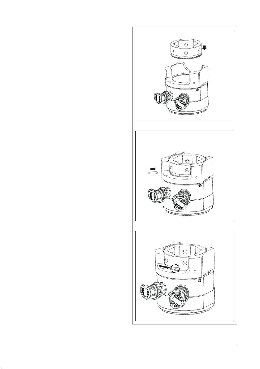
4. Place the tensioner over the stud, ensuring
that the socket fits over the nut without
force. See Figure 6, View A.
a. Ensure that the tommy bar slot in the
bridge faces outward.
b. Ensure that the hydraulic couplers are
positioned outward, to allow easier
connection of hydraulic hoses.
Note: GT bridges and sockets manufactured
prior to 2019 and which have a Date Code
of A, will not have the socket captivation
feature. For GT Tensioners with a Date Code
of A, position the socket over the nut; ensure
that the socket fits over the nut without
force. Place the tensioner over the stud.
5. Locate the end of the stud with the
threaded
puller. Using a tommy bar, screw
down the threaded puller on the stud until
the puller shoulder seats firmly against the
piston. See Figure 6, View B.
6. Assemble any additional tensioners in the
system in the same manner, following
steps 3 through 6 of this section.
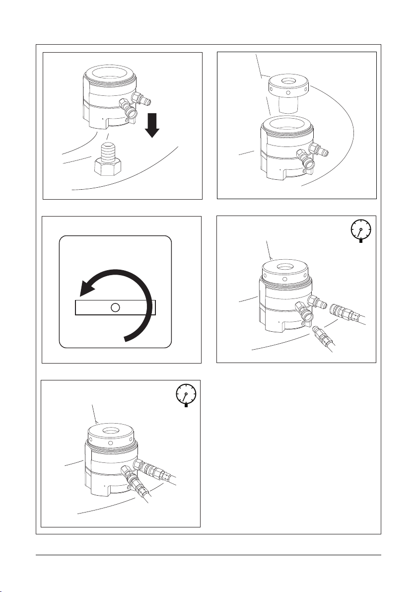
7. Check that the pump pressure release
valve
is OPEN. See Figure 6, View C.
8. Connect hydraulic hoses to the tensioners.
See Figure 6, views D and E. Also refer to
Section 6.3 for typical hose connection
arrangements.
9. At each stud, verify that the piston is
fully retracted into the tensioner body. If
necessary, turn down the threaded puller
(as required) to fully retract the piston.
10. Before pressurizing the system, be sure
that all hydraulic hoses are connected.
Each male coupler must be connected to
a corresponding female coupler. Verify that
each coupler is fully engaged and securely
locked into position by physically pulling
on the connection.
IMPORTANT: ONLY the unused female coupler
on the LAST tensioner at the end of the circuit
can remain disconnected. A blanking plug must
be installed in this coupler before beginning
pressurization.
Never pressurize the back side
of a disconnected (open ended) male coupler.
Disconnected male couplers may leak when
pressurized from the back side. Serious
personal injury could result if leakage occurs,
and a high pressure oil stream penetrates the
skin.
If only a single tensioner is being
used, always pressurize the tensioner using
ONLY the MALE tensioner coupler. To prevent
possible high pressure oil leakage, NEVER use
the female tensioner coupler to pressurize a
single tensioner.
WARNING
WARNING

8© 2019 Enerpac, All Rights Reserved.
FIGURE 6, HYDRAULIC TENSIONER INSTALLATION
A
C
PRESSURE
RELEASE
OPEN
E
0
B
D
0
PRESSURE
RELEASE
OPEN

© 2019 Enerpac, All Rights Reserved. 9
6.3 Tensioner Arrangements (typical)
Hydraulic tensioners can be mounted on either
one or both sides of the joint, depending on
available clearance and work room. Whenever
possible, all studs on the joint should be
tensioned at the same time. Typical examples of
100% and 50% tensioner coverage are shown
in Figure 7. Contact Enerpac for additional
information regarding tensioner arrangements
of less than 50% coverage.
Note: For less than 100% coverage, divide the
quantity of tensioners available into the quantity
of studs in the joint. This will determine the stud
locations to be tightened during each pass. For
example, if 18 tensioners are available for a 36
bolt joint, then every second stud will contain a
tensioner (50% coverage). If 12 tensioners are
available, then every third stud will contain a
tensioner (33% coverage).
100% Coverage
(typical arrangement)
Note: Using this method of assembly,
all studs are tightened simultaneously
in one operation. To allow room for all
tensioners, the protruding studs must
be staggered over each side of the
joint (see above).
Interconnecting hose Feed Hose to Pump
Note: In stage one,
50 % of the studs are
tensioned. In stage
two, the remaining
50% of the studs are
tensioned.
Note: This method of assembly
is often used where studs can be
tensioned from only one side of the
joint due to an access restriction on
the opposite side. The studs must
be assembled with the protrusions
on the same side of the joint (see
below).
50% Coverage
(typical arrangement)
Interconnecting hose
Feed Hose to
Pump
FIGURE 7, HYDRAULIC TENSIONER MOUNTING ARRANGEMENTS (TYPICAL)

10 © 2019 Enerpac, All Rights Reserved.
7.0
TENSIONING AND DE-TENSIONING
Never stand in-line with the bolt axis while the
system is pressurized. If the bolt should fail,
serious personal injury or death could result if
loose or broken parts become projectiles. All
personnel must be aware of this potential hazard
at all times.
Ensure that the maximum working
pressure and maximum stroke are not exceeded.
Refer to the specifications stamped on the
tensioner body. Also see Table 2 at the end of
this document.
IMPORTANT: If the maximum stroke indicator
appears at any time during the following
procedures, immediately STOP the pump, tighten
nut(s) at the tensioner(s) and release hydraulic
pressure. Then, turn down the threaded puller(s)
to return the piston(s) back into the tensioner(s)
before continuing. Refer to Section 4.1 for
additional information.
IMPORTANT: If any leaks occur, immediately
stop the pump and open the pressure release
(return-to-tank) valve. Be sure that the oil pressure
gauge indicates zero (0) psi/bar. Make repairs
as required before continuing with tensioning
procedures.
Note: For improved illustration clarity, only
one hydraulic hose is shown connected to the
tensioner in figures 7 to 11.
7.1 Tensioning Instructions - 100% Coverage
(tensioner installed on each stud)
IMPORTANT: Read precautions and instructions
at beginning of Section 7.0 before beginning the
following steps. Also refer to safety information
contained in Section 2.0.
1. Ensure that the joint is correctly aligned.
2. Assemble the tensioner(s) to the stud(s)
and connect hydraulic hoses. Refer
to sections 6.1 and 6.2 for additional
tensioner installation and hose connection
instructions.
3. Determine the required hydraulic tensioning
pressure. This value must be calculated by a
qualified engineer with bolting experience.
4. Operate the pump and pressurize the
tensioners up to approximately 1000 psi
[70 bar]. Check for oil leaks.
WARNING
PRESSURE
RELEASE
CLOSED
FIGURE 8, PRESSURIZING THE TENSIONER
PRESSURE
RELEASE
CLOSED
FIGURE 9, TURNING DOWN THE SOCKET
AND NUT
5. If no leaks are found, continue pressurizing
the tensioners to the calculated value
determined in step 3. Continually observe
the tensioner stroke and hydraulic
pressure at all times during pressurization.
6. When the calculated hydraulic pressure
is
reached, stop the pump. Recheck the oil
pressure gauge after pump has stopped.
Be sure the pressure is stable (not
increasing or decreasing). Threads may
be visible between the nut and the joint
surface at each tensioner. See Figure 8.
7. While holding the pressure constant, use
a tommy bar to turn down the first socket
and nut by hand. Continue tightening until
the nut is firmly seated against the joint
surface. See figures 9 and 10.
8. Repeat step 7 for all remaining studs in the
circuit.

© 2019 Enerpac, All Rights Reserved. 11
PRESSURE
RELEASE
OPEN
FIGURE 11, PRESSURE RELEASED AFTER
TURNING DOWN NUT
0
PRESSURE
RELEASE
CLOSED
FIGURE 10, SOCKET AND NUT FIRM
AGAINST JOINT
NO Threads
FIGURE 12, TURNING DOWN THE THREADED
PULLER (AS REQUIRED)
0
PRESSURE
RELEASE
OPEN
9. Release the hydraulic pressure by SLOWLY
opening the pump pressure release (return
to tank) valve. Verify that the oil pressure
gauge indicates zero (0) psi/bar. See
Figure 11.
10. Check the piston stroke. If necessary, turn
down the threaded puller until the piston is
fully retracted into the tensioner body. See
Figure 12.
11. Repeat steps 4 through 10 a second time.
12. Repeat steps 4 through 10 a third time.
13. As an optional check, apply hydraulic
pressure a fourth time and attempt to
tighten the nuts again.
• If the nuts cannot be turned, then
tensioning is complete. Relieve hydraulic
pressure. Go to Step 14.
• If the nuts can still be turned, repeat steps
4 through 10 until no additional movement
can be obtained. However, caution must
be observed as excessive movement
may indicate that a joint problem exists.
14. Verify that the oil pressure gauge indicates
zero (0) psi/bar. If any pressure is indicated,
release the hydraulic pressure by SLOWLY
opening the pump pressure release (return
to tank) valve.
15. Turn down the threaded pullers until the
pistons are fully retracted. Disconnect
hydraulic hoses and install a dust cap (not
shown) over each disconnected coupler.
Remove tensioners from the studs.
7.2 Tensioning Instructions - 50% Coverage
(tensioner installed on every other stud)
IMPORTANT: Read precautions and
instructions at beginning of Section 7.0 before
beginning the following steps. Also refer to
safety information contained in Section 2.0.
1. Ensure that the joint is correctly aligned.
2. Alternately number each bolt “1” and “2”
for future reference.
3. Assemble the tensioner(s) to the studs
marked “1” and connect the hydraulic
hoses. See Figure 13 for typical tensioner
arrangement. Also refer to sections 6.1 and
6.2 for additional tensioner installation and
hook-up instructions.

4. Determine the “first pass” pressure “A”
value. This value must be calculated by a
qualified engineer with bolting experience.
Note: The pressure “A” value used to tension
the bolts marked “1” is typically higher than
the pressure “B” value used later to tighten the
bolts marked “2”. This is to allow for additional
load losses which may occur when performing
less than 100% coverage tensioning.
5. Operate the pump and pressurize the
tensioners up to approximately 1000 psi
[70 bar]. Check for oil leaks.
6. If no leaks are found, restart the pump
and pressurize the tensioners to the “first
pass” pressure “A” value determined in
step 4. Continually observe the tensioner
stroke and hydraulic pressure at all times
during pressurization.
7. When the “first pass” pressure “A” is
reached, stop the pump. Recheck the oil
pressure gauge after pump has stopped.
Be sure the pressure remains stable (not
increasing or decreasing). Threads may
be visible between the nut and the joint
surface at each tensioner. See Figure 8.
8. While holding the pressure constant, use
a tommy bar to turn down the first socket
and nut by hand. Continue tightening until
the nut is firmly seated against the joint
surface. See figures 9 and 10.
9. Repeat step 8 for the remaining “first
pass” tensioners in the circuit.
10. Release the hydraulic pressure by
SLOWLY opening the pump pressure
release (return to tank) valve. Verify that
the oil pressure gauge indicates zero
(0) psi/bar. See Figure 11.
11. Check the piston stroke at each tensioner
in the circuit. If necessary, turn down the
threaded puller until the piston is fully
retracted into the tensioner body. See
Figure 13.
12. Repeat steps 5 through 11 a second time
(to pressure “A”).
13. Repeat steps 5 through 11 a third time (to
pressure “A”).
14. Move the tensioners to the remaining
50%
of the bolts (i.e. all bolts numbered “2”).
See Figure 14.
15. Determine the “second pass” pressure
“B” value. This value must be calculated
by a qualified engineer with bolting
experience.
Note: The pressure “B” value is typically lower
than the pressure “A” value (see note after step
4 for additional information).
1 1
1 1
11
2
2
22
2 2
A
FIGURE 13, TENSIONER ARRANGEMENT,
FIRST PASS - TYPICAL (50% TENSIONER
COVERAGE)
Apply Pressure “A”
(At all studs marked “1”)
12 © 2019 Enerpac, All Rights Reserved.
FIGURE 14, TENSIONER ARRANGEMENT
SECOND PASS - TYPICAL (50% TENSIONER
COVERAGE)
Apply Pressure “B”
(At all studs marked “2)
1 1
1 1
11
2
2
22
2 2
B

FIGURE 15, RECHECKING FIRST PASS
TENSIONER (50% TENSIONER COVERAGE)
1 1
1 1
11
2
2
22
2 2
B
1
1
Apply Pressure “B”
(At two diametrically
opposite studs marked “1”)
16. Operate the pump and pressurize the
tensioners up to approximately 1000 psi
[70 bar]. Check for oil leaks.
17. If no leaks are found, continue pressurizing
the tensioners to the calculated “second
pass” pressure “B” value determined in
step 15. Continually observe the tensioner
stroke and hydraulic pressure at all times
during pressurization.
18. When the “second pass” pressure “B” is
reached, stop the pump. Recheck the oil
pressure gauge after pump has stopped.
Be sure the pressure remains stable (not
increasing or decreasing). Threads may
be visible between the nut and the joint
surface at each tensioner. See Figure 8.
19. While holding the pressure constant, use
a tommy bar to turn down the first socket
and nut by hand. Continue tightening until
the nut is firmly seated against the joint
surface. See figures 9 and 10.
20. Repeat step 19 for the remaining “second
pass” tensioners in the circuit.
21. Release the hydraulic pressure by
SLOWLY opening the pump pressure
release (return to tank) valve. Verify that
the oil pressure gauge indicates zero
(0) psi/bar. See Figure 11.
22. Check the piston stroke at each tensioner
in the circuit. If necessary, turn down the
threaded puller until the piston is fully
retracted into the tensioner body. See
Figure 12.
23. Repeat steps 16 through 22 a second time
(to pressure “B”).
24. Repeat steps 16 through 22 a third time
(to pressure “B”).
25. As an optional check to determine
if an excessive load has been lost
in the first 50% of bolts tightened
(bolts numbered “1”):
a. Assemble tensioners on
any two “first pass” bolts
(labeled “1”) located diametrically
opposite of each other. See Figure 15.
b. Connect hydraulic hoses.
c. Apply the “second pass” pressure “B”.
d. Using the tommy bar, attempt to
tighten the nuts on these bolts by
hand.
• If the nuts cannot be turned, then
tensioning is complete. Relieve hydraulic
pressure. Go to step 26.
• If the nuts can be turned, then re-install
the tensioners to the remainder of the
“first pass” bolts (numbered “1”), apply
the “second pass” pressure “B” and
turn-down the nuts one more time as
described in steps 16 through 22.
26. Verify that the oil pressure gauge indicates
zero (0) psi/bar. If any pressure is
indicated, release the hydraulic pressure
SLOWLY by opening the pump pressure
release (return to tank) valve.
27. Turn down the threaded pullers until the
pistons are fully retracted. Disconnect
hydraulic hoses and install a dust cap (not
shown) over each disconnected coupler.
Remove tensioners from the studs.
7.3 De-tensioning Instructions - 100%
Coverage (tensioner installed on each
stud)
IMPORTANT: Read precautions and
instructions at beginning of Section 7.0 before
beginning the following steps. Also refer to
safety information contained in Section 2.0.
© 2019 Enerpac, All Rights Reserved. 13

Note: For improved illustration clarity, only
one hydraulic hose is shown connected to the
tensioner in figures 16-19.
1.
Assemble the tensioner(s) to the stud(s) to
be de-tensioned and connect the hydraulic
hoses. Refer to sections 6.1 and 6.2 for
additional tensioner installation and hose
connection instructions.
2. BEFORE applying any hydraulic pressure,
turn up the threaded puller at each stud as
required, so that approximately a 3/16 inch
[5 mm] gap appears between the fully
retracted piston and the threaded puller.
See Figure 16.
3. Operate the pump to pressurize the
tensioners up to approximately 1000 psi
[70 bar]. Check for oil leaks.
In the following de-tensioning
steps, be certain that the hydraulic pressure
remains below the maximum allowable
hydraulic pressure of 21,750 psi [1500 bar], and
that the load applied does not exceed the tensile
strength of the stud.
4. If no leaks are found, continue operating
the pump. Slowly raise the pressure until
the “break loose” hydraulic pressure value
is reached. This is the pressure at which
a nut on one of the tensioners just begins
to loosen and can be turned by hand with
the tommy bar. Record this pressure for
reference. See Figure 17.
5. Increase the hydraulic pressure
approximately 5 percent above the “break
loose” pressure recorded in step 4. Then,
stop the pump.
6. While holding the pressure constant, turn
up (loosen) the nut at the first tensioner,
so that there is approximately a 1/8 inch
[3-4 mm] gap between the nut and the joint
surface. See Figure 18.
Note: Dimension of gap in step 6 must not
exceed the dimension of gap in step 2.
7. Repeat step 6 at all remaining studs.
If nuts are dicult to turn, hydraulic
pressure may be increased in additional
5 percent increments. However, NEVER raise
hydraulic pressure above 21,750 psi [1500 bar].
Ensure that the load applied does not exceed
the tensile strength of the stud.
WARNING
CAUTION
3/16 inch [5mm]
0
FIGURE 16, TURNING UP THE THREADED
PULLER
PRESSURE
RELEASE
OPEN
B1
FIGURE 17, DETERMINING THE “BREAK
LOOSE” PRESSURE
Note: Try to turn up the
nut while slowly raising the
hydraulic pressure. When the
nut just begins to turn, the
“break loose” pressure (B1) has
been reached.
B1= Break Loose Pressure
PRESSURE
RELEASE
CLOSED
B1 B2
FIGURE 18, TURNING UP THE NUT
1/8 inch
[3-4mm]
B2= Break Loose Pressure (B1) + 5%
PRESSURE
RELEASE
CLOSED
14 © 2019 Enerpac, All Rights Reserved.

8. Release the hydraulic pressure by SLOWLY
opening the pump pressure release (return
to tank) valve. Verify that the oil pressure
gauge indicates zero (0) psi/bar. See Figure
19. The studs are now fully de-tensioned.
9. Turn down the threaded pullers until the
pistons are fully retracted. Disconnect
hydraulic hoses and install a dust cap (not
shown) over each disconnected coupler.
Remove tensioners from the studs.
7.4 De-tensioning Instructions - 50%
Coverage (tensioner installed on every
other stud)
IMPORTANT: Read precautions and
instructions at beginning of Section 7.0 before
beginning the following steps. Also refer to
safety information contained in Section 2.0.
1. Assemble the tensioner(s) to the first 50%
of stud(s) to be de-tensioned and connect
the hydraulic hoses. Refer to sections 6.1
and 6.2 for additional tensioner installation
and hose connection instructions.
2. Follow steps 2 through 8 of Section 7.3 for
the first 50% of studs.
3. Move the tensioners to the second 50% of
studs.
4. Follow steps 2 through 9 of Section 7.3 for
the remaining 50% of studs. Note that the
“break loose” hydraulic pressure for the
second set of studs will likely be about the
same or slightly lower than that for the first
set.
FIGURE 19, PRESSURE RELEASED - NUT
DE-TENSIONED
PRESSURE
RELEASE
OPEN
8.0 MAINTENANCE
It is recommended that repairs and servicing
be carried out by Enerpac at intervals agreed
by Enerpac and customer. All parts will be
thoroughly inspected and replaced where
necessary, certain components (e.g. seals)
will be replaced automatically. Tensioners will
be re-assembled, pressure tested and a test
certificate issued.
Note: All parts will have been manufactured,
inspected and tested in accordance with
Enerpac’s stringent requirements. Any parts
failing in use that are found upon Enerpac’s
inspection not to be Enerpac’s genuine spare
parts will invalidate any operative warranty or
guarantee.
The tool is of rugged construction and utilises
reliable seals. The only maintenance that may
be occasionally required is the replacement of
seals or repair of a hydraulic fitting.
Note: It is strongly recommended that in the
event of seal failure the tensioners are returned
to Enerpac for seal replacement, however if this
is not possible then the enclosed procedure
should be followed.
8.1 Pre-Use Maintenance
Assemble the tensioner onto a suitable bolt
(see Section 6.0), check that the bolt material
is capable of taking the applied load i.e. do not
pressurise to max working pressure if the bolt
is not strong enough to withstand the full load
of the tool.
Pressurize for approximately one minute, a
pressure drop of 50 bar is acceptable during
this time.
If the tensioner passes this test, then the ram
should be reset and the tensioner is ready for
use.
If any leakage is noticed within the head
assembly, then a full strip down will be
necessary to change the seals, as described
in Section 8.4.
8.2 Post-Use Maintenance
In order to keep the equipment in good working
condition it is important that at the end of each
period of use, prior to being replaced into dry
storage, a post-use maintenance is carried out.
© 2019 Enerpac, All Rights Reserved. 15

Note: All parts will have been manufactured,
inspected and tested in accordance with
Enerpac’s stringent requirements. Any parts
failing in use that are found upon Enerpac’s
inspection not to be Enerpac’s genuine spare
parts will invalidate any operative warranty or
guarantee.
Remove the bridge assembly from the head
assembly. Inspect each sub assembly for any
visible damage/leaks etc.
With the ram fully retracted in the head
assembly, unscrew the quick disconnect
couplers.
Replace the seals as described in Section 8.4.
Refit the springs, spring housing and quick
disconnect couplers.
Clean the puller, particularly the thread, and
bridge assembly (if necessary remove the
retaining pins and socket).
Assemble the tensioner onto a suitable bolt
(see Section 6.2) check that the bolt material
is capable of taking the applied load i.e. do not
pressurise to max working pressure if the bolt
is not strong enough to withstand the full load
of the tool. Pressurize for approximately one
minute, a pressure drop of 50 bar is acceptable
during this time.Having removed the tensioner
from the bolt, coat each sub-assembly in a
water repellent spray such as WD40 or similar.
Replace the dust caps on the quick disconnect
couplers.
8.4 Changing Tensioner Seals
1. Precautions
The following precautions must be taken with
the assembly of the hydraulic seals:
• Avoid sharp edges (cover thread areas)
• Remove all dust, dirt, swarf and foreign
particles.
• Do not use sharp edged tools.
• Lubricate all components before assembly.
Hydraulic seal replacement must only be
carried out should the seals become damaged.
The seals should not be removed during routine
maintenance.
1. GT Tensioner
The ram should be reset and all parts should be
cleaned down, and coated with WD40 or simi-
lar. Alternatively rinse in light oil.
Replace the dust caps on the quick disconnect
couplers to prevent the ingress of dirt.
If any leakage is noticed within the head
assembly, then a full strip down will be
necessary to change the seals, as described in
Section 8.4. If tensioners are subject to a lot of
use it is advisable to fully strip them and clean
and inspect all components, at least once a
year. Refer to Section 8.3.
2. Bridge
Ensure that the socket is free to rotate inside
the bridge.
Ensure that the socket retaining pins are intact.
Inspect for damage and clean down with light
oil before storing.
3. Puller
Ensure that the threads are free from damage
by screwing it down a suitably sized bolt.
Clean down the puller with light oil before
storing.
4. Hoses and Ancillaries
Clean, then coat each quick disconnect coupler
in a water repellent spray such as WD40 or
similar, retracting and releasing the collars
several times. Ensure that the collars do not
seize in the retracted position. Visually inspect
the entire length of the hose for damage. Test
to maximum working pressure (ensure blanking
plugs inserted into end of coupler).
8.3 GT Tensioner Full Maintenance/ Servicing
It is recommended that repairs and servicing
be carried out by Enerpac at intervals
agreed by Enerpac and customer. All parts
will be thoroughly inspected, specified parts
will be non-destructively tested using MPI
techniques and replaced where necessary,
certain components (e.g. seals) will be replaced
automatically.
Tensioners will be re-assembled, pressure
tested and a test certificate issued.
16 © 2019 Enerpac, All Rights Reserved.

2. Ram
Legend for Figures
1. Seal
2. Ram
3. Anti-Extrusion Ring (AER)
4. Pliers
5. Blunt Edged Dolly
3. Seal Removal
Fit an open-ended female quick-disconnect
coupler to a tensioner coupler. Using the flat
blade of a screwdriver, lever the piston out of
the tensioner body.
To remove the hydraulic seals and Anti-
Extrusion Rings (AER’s):
Using a pair of pliers, grip the sealing lip of the
hydraulic seal and pull the seal away from the
ram. Take care not to damage the edge of the
ram.
FIGURE 20 - REMOVAL OF SEALS
Discard the seal, remove the extraction bolts
and replace the two plastic grub screws.
4. Seal Replacement
Inspect the seal housing grooves within the
ram. Using either a clean cloth or compressed
air, remove all dirt and debris from the ram
and body. It is very important that all dust and
debris be removed from the seal/AER as failure
to do so may result in seal failure.
Fit the AER’s to the seal, the tapered surface
of the AER must face the taper of the seal as
shown below. This applies to both outer and
inner AER’s.
FIGURE 21 - AER LOCATION
Install the seal assembly into the ram, pressing
down firmly until the seal fully enters the ram
seal housing.
Engage the seal retaining clip by pushing down
around the periphery using a blunt edged dolly
in the position shown below. A ‘click’ will be
sensed when the seal fully engages.
FIGURE 22 - ENGAGING THE SEAL
When there are no gaps between the ram, AER
and seal the assembly is correct, see below.
FIGURE 23A - INCORRECT AER ASSEMBLY
FIGURE 23B - CORRECT AER ASSEMBLY
Lubricate the seal and tensioner bores with
silicone grease or clean hydraulic oil in
preparation of installing the ram.
© 2019 Enerpac, All Rights Reserved. 17

Lubricate the thread on the adaptor with
Omega 95 (or similar lubricant with a coefficient
of friction = 0.12), and tighten to a torque of
45 lbf.ft [61 Nm]. Ensure that the bonded seal
does not become nipped or dislodged during
tightening.
IMPORTANT: Care must be taken not to over
tighten the adaptors into the tensioner and
to use the hexagon on the adaptor to pull
it in rather than the hexagon on the male
quick disconnect coupler which could induce
bending, leading to failure.
9.0 STORAGE
Store tools fully retracted.
The finish will protect the tools from rust etc.
but for added protection a light coating of oil
or rust inhibitor should be applied to all plated
surfaces.
Cover the internal threads on the inside of the
puller bar and reaction nuts with a rust inhibitor.
Store tools upright.
Keep dust caps on the oil inlet couplers.
Hydraulic Hose(s)
Wipe all hoses clean and apply a light coating
of oil or suitable rust inhibitor to all couplers
and tee blocks.
Always keep dust caps fitted to couplers.
Pump Unit
Always store the pump upright.
Apply a light oil coating or suitable rust inhibitor
to all exposed unplated metal items.
Leave the oil return to tank valve in the open
position.
Always keep dust caps on inlet and outlet
hydraulic fittings.
Push the ram into the body bore ensuring that
the seal does not become nipped. The outer
seal will be the first to enter and can be used as
a guide to square up the ram prior to entering
the inner seal. Should difficulty be encountered
in entering seals, a slight rotation of the ram
whilst pushing the ram into the body may aid
the installation.
5. Coupler Seals - 1/4” BSP Fittings
A simple sealing arrangement exists between
the GT tensioner body and the coupler. The seal
is a 21,750 psi [1500 bar] rated Bonded Seal; it
is located inside a counterbore on the tensioner
body behind the coupler. Should the seal leak
or become damaged then it should be replaced
as follows.
Unscrew the male quick-disconnect coupler.
Note: A 1/4” BSP threaded adaptor is fitted
into the male quick-disconnect coupler. Under
normal circumstances this will remain an
integral part of the coupler and should not be
removed. However, should the adaptor and
coupler become separated or unscrewed, then
the adaptor must be reassembled into the
coupler and re-tightened. The 1/4” BSP adaptor
must never be installed into the tensioner body
before the coupler and seals are attached.
Follow the procedure below if the adaptor has
separated from the coupler.
a. Clean the coupler thread and adaptor,
removing all traces of debris.
b. Coat the end of the adaptor which is to be
screwed into the coupler (i.e. the end with
the spigot and the female hexagon), with
‘Loctite 270’ and screw into the coupler
until it is finger tight.
c. Remove surplus ‘Loctite’.
d. Leave the assembly for a minimum of
30 minutes curing time before proceeding
with assembly into the GT tensioner body.
Remove and discard the bonded seal.
Clean any dirt and debris from the tensioner
body counterbore and the coupler spigot face.
Insert a new bonded seal into the counterbore.
18 © 2019 Enerpac, All Rights Reserved.
Other manuals for GT Series
1
This manual suits for next models
7
Table of contents
Other Enerpac Tools manuals

Enerpac
Enerpac SWE189DTTC-NBT User manual

Enerpac
Enerpac WR-5 User manual

Enerpac
Enerpac HPH14 User manual

Enerpac
Enerpac ATM-2 User manual

Enerpac
Enerpac ATM-9 User manual

Enerpac
Enerpac ATM-4 User manual

Enerpac
Enerpac CT-604 User manual

Enerpac
Enerpac E Series User manual

Enerpac
Enerpac SWE189DTTA User manual

Enerpac
Enerpac ATM Series User manual