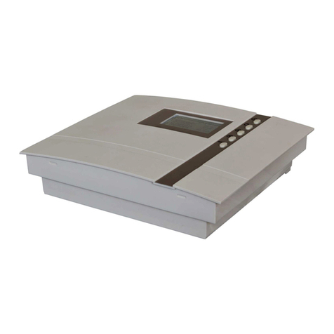
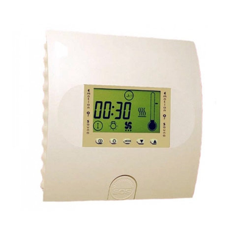
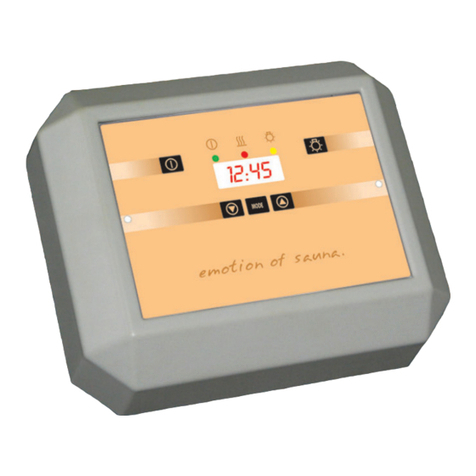
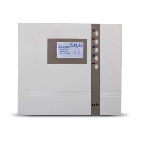
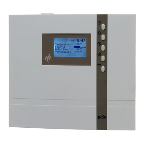
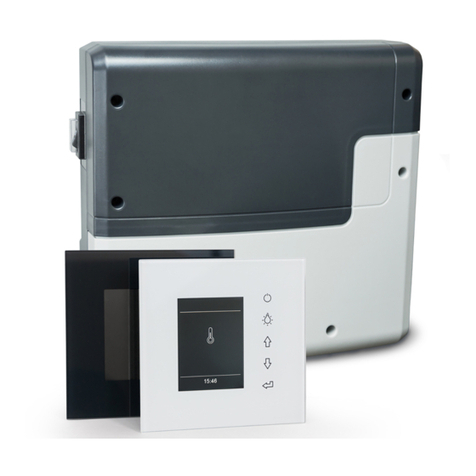
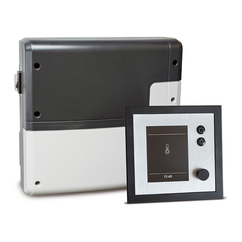
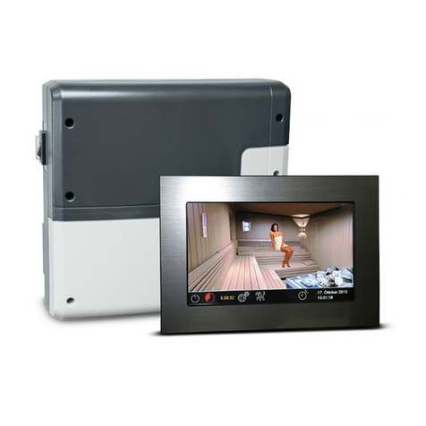
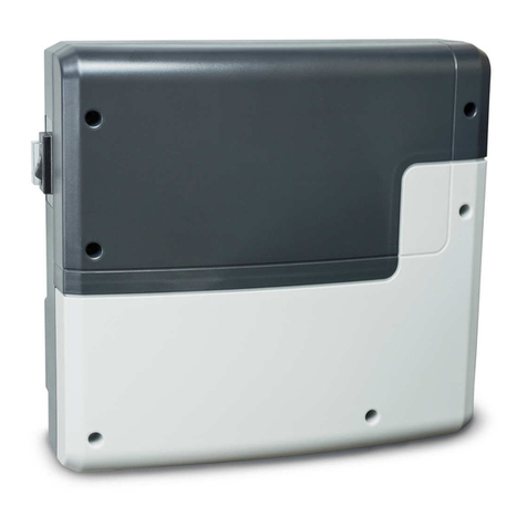
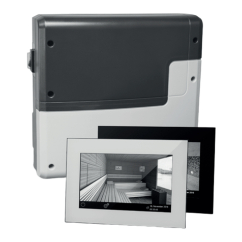
EOS ECON H4 User guide

1
D
IP x4
Made in Germany
Druck Nr. 29344631en / 49.15
ECON H4
GB Installation and operating instruction
sauna control unit

2GB
English
content
Scope of Delivery .........................................................................................................................................4
Technical data.................................................................................................................................................5
General information about using the sauna.......................................................................................6
General safety information........................................................................................................................7
Assembly of the control unit.....................................................................................................................9
Assembly on the wall.............................................................................................................................9
Assembly in the wall ........................................................................................................................... 10
Connection of the sensor lines.............................................................................................................. 11
Assembly of the stove sensor .......................................................................................................... 11
Installing the optional bench sensor ............................................................................................ 13
Electrical connection ................................................................................................................................ 14
Connecting the sauna heater .......................................................................................................... 14
Connection of a load switching unit (LSG) ................................................................................. 14
Connecting the vaporizer ................................................................................................................. 14
Connecting the sauna lamp............................................................................................................. 14
Connecting a fan.................................................................................................................................. 14
Installation diagram ............................................................................................................................ 15
Terminal arrangement on the circuit board. ............................................................................. 15
Wiring diagram sauna heater up to 9 kW.................................................................................... 16
Wiring diagram sauna heater > 9 kW............................................................................................ 16
Wiring diagram vaporizer.................................................................................................................. 17
Assembly and connection of the optional humidity sensor ................................................ 17
Operation...................................................................................................................................................... 18
General..................................................................................................................................................... 18
The user interface .......................................................................................................................... 18
Control buttons .............................................................................................................................. 18
Basic stand by screen.................................................................................................................... 19
Basic operating screen................................................................................................................. 19
Energy-saving screen.................................................................................................................... 19
Cabin lighting.................................................................................................................................. 20
Fans ..................................................................................................................................................... 21
Initial commissioning ................................................................................................................... 22
Changing the language............................................................................................................... 23
Changing the time......................................................................................................................... 23
Activating the Life-Guard............................................................................................................ 24
Activation/deactivation of the child lock.............................................................................. 24

3
GB
Activation of the sauna stove .................................................................................................... 25
Deactivation of the sauna stove in Finnish mode.............................................................. 25
Activation of the sauna stove with Life-Guard.................................................................... 25
Individual settings ............................................................................................................................... 26
Cabin temperature ........................................................................................................................ 26
Humidity mode for time steps .................................................................................................. 27
Humidity intensity......................................................................................................................... 27
Humidity mode for humidity sensor....................................................................................... 29
Humidity intensity ...................................................................................................................29-30
Deactivation of the sauna system in humidity mode....................................................... 30
Auto-stop.......................................................................................................................................... 31
Preselection time ........................................................................................................................... 33
Activation of the preselection time......................................................................................... 34
Deactivation of the preselection time................................................................................... 34
Life-Guard......................................................................................................................................... 35
Extend heat-up time restriction............................................................................................................ 36
Replace device fuse...................................................................................................................................36
Error messages ............................................................................................................................................ 37
The device switch (switch-off) .............................................................................................................. 38
Manual specification of the lighting ................................................................................................... 39
Holiday home mode ................................................................................................................................. 40
Recycling ....................................................................................................................................................... 41
Service address ........................................................................................................................................... 41
Guarantee ..................................................................................................................................................... 41
General Terms and Conditions of Service.......................................................................................... 42

4GB
Standard delivery
(Subject to change)
Included in control unit scope of delivery:
1. Stove sensor board with over-temperature fuse, PTC sensor with sensor housing, two attach-
ment screws 3 x 25 mm and sensor cable approx. 2.0 m long.
2. Plastic bag containing three mounting screws 4 x 20 mm.
3. Spare over-temperature protection

5
GB
Technical data
• Rated voltage: 400 V 3 N 50 Hz AC
• Switch output: max. 9 kW resistive load (AC1 mode) Humidity mode:
6 kW + 3 kW for vaporizer equipment. Can be expan-
ded to 36 kW via the connection of power switching
devices
• Heat-up time restriction: 6 h, 12 h / without heat-up time restriction
• Display: LCD display 65 x 37 mm, graphic
• Dimensions (HxWxD): 220 x 250 x 67 mm
• Protection class: IPx4 acc. to EN 60529 splashwater protection
• Control range in the sauna mode: 30 to 115°C
• Control range in the humidity mode: 30 to 70°C
• Humidity control (without humidity sensor): time-proportional (10 levels)
• Humidity control (with humidity sensor): Permanent control via the humidity sensor F2 (with
humidity sensor Art.-No. 909479 or 945027 according
to EN 60335-2-53). See information!
• Sensor system (temperature): PTC sensor with safety temperature limiter 142°C
• Water level monitoring: Lack of water in the vaporizer will cause the heating
system to shut down after 2 minutes.
• Control characteristic: Two-point control with xed hysteresis of 3K.
For control via the stove sensor oset of 7K to com-
pensate the higher temperatures directly below the
cabin ceiling
• Fan output: max. 100 W, no capacitor motors, controlled via phase
control
• Light: max. 100 W (automatic switching phase control / pha-
se cut-o)
• Re-heating: 30 min. at 90°C after the humidity program has been
stopped
• Ambient temperatures: -10°C to +40°C
• Storage temperature: -20°C to +70°C
• Temperature display stove sensor Current value on the stove sensor minus 7K to com-
pensate the higher temperatures directly below the
cabin ceiling
• Temperature display bench sensor: Current value on the bench sensor

Dear customer
You have purchased a high-quality technical
device with which you will have years of sauna
fun. This sauna control unit was designed and
inspected according to the current European
safety standards and manufactured at the facto-
ry in accordance with the quality management
standard DIN EN ISO 9001:2000.
This detailed installation and operation manual
has been prepared for your information. Please
observe in particular the important notes and
the information on electrical connection.
We wish you exhilarating recreational experience
and lots of fun with your sauna!
Intended use
This sauna control unit is exclusively intended
for the control of the sauna heater in a sauna
cabin.
Any other use over and above the intended
purpose is not considered as appropriate use!
Compliance of the standard operation, mainte-
nance and repair conditions is also an element
of appropriate use.
The manufacturer cannot be held liable for
deviating, unauthorized alterations and any re-
sulting damages: the initiator of these changes
bears the full risk.
General information
Please check whether the unit has arrived in per-
fect condition. Any transport damages should be
immediately reported to the freight forwarder
delivering the goods or you should contact the
company that shipped the goods.
Please note that you will only be able to achieve
an optimum sauna climate if the cabin with its air
intake and ventilation, the sauna heater and the
control unit are aligned to each other.
Please observe the information and stipulations
made by your sauna supplier.
Sauna heaters heat up your sauna cabin using
heated convective air. Here, fresh air is drawn
in from the air intake which, when heated, rises
upwards (convection) and is then circulated
within the cabin. Part of the used air is pushed
out through the vent in the cabin. This creates a
typical sauna climate which can achieve temper-
atures of approx. 110°C measured directly under
the ceiling of your sauna, dropping in temper-
ature to approx. 30-40°C towards the oor. It is
therefore not unusual to measure temperatures
of 110°C on the temperature sensor hanging
over the heater, whilst the thermometer hanging
on the sauna wall, approx. 20-25 cm under the
cabin ceiling, only indicates 85°C. The bathing
temperature generally lies between 80°C and
90°C in the area of the upper bench when the
temperature is set to maximum.
Please note that the highest temperatures are
always generated over the sauna heater and that
the temperature sensor and the safety limiter
must be mounted there in accordance with the
control unit installation instructions.
When heating up for the first time, you may
notice a slight smell caused by evaporating
lubricants used in production processes. Please
ventilate your cabin before beginning your
sauna bath.
6GB

General safety precautions
• This device can be used by children aged
8 upwards and by persons with physical,
sensory, or mental disabilities, or who
have inadequate experience and knowl-
edge if they are supervised or if they have
received adequate instruction in how to
use the device safely and understand the
associated risks. Children may not play
with this device. Children may not clean
or carry out any user maintenance if un-
supervised.
• Children are to be supervised in order to
make sure that they do not play with this
device.
•
!
!
!
!
!
!
!
!
!
!
!
!
!
!
!
!
!
!
!
!
Attention: It is forbidden to install
the control box in a closed switch cabinet
or behind a wooden panelling!
• The electrical installation may be done
only by a qualied electrical technician.
• You must comply with the regulations of
your power supply company and applica-
ble VDE regulations (DIN VDE 0100).
•
!
!
!
!
!
!
!
!
!
!
!
!
!
!
!
!
!
!
WARNING: Never attempt repairs or
installations yourself, as this could result
in serious injury or death. Only a qualied
technician may remove the housing cover.
• Please note the dimensions in the assem-
bly instructions, especially when installing
the temperature sensor. The temperature
above the oven is critical for the temper-
ature setting. The temperature can be
held within operating parameters and
a minimal temperature gradient inside
the bench area of the sauna cabin can be
achieved only if unit is assembled correct-
ly.
• The device may only be used as intended
as a control unit for sauna ovens up to 9
kW (up to 36 kW when combined with a
contactor box).
• Completely disconnect the control unit
from the electrical circuit, i.e. ip all circuit
breakers or the main circuit breaker during
each installation or repair.
• Please note the safety and installation
information from the sauna oven manu-
facturer.
• Always heed the specications and in-
structions of the cabin manufacturer, too.
• If control units with remote con-
trol options* are used, protection
against activation when the heater is
covered is required. (e.g. cover protec-
tion Type 1-5 or S-Guard).
*Telecontrol = setting up, controlling or adjusting a
unit by a command that can be given out of view
of the unit by means of transfer media such as tele-
communication, audio technology or bus systems.
(this also includes weekly timers)
7
GB

!
!
!
!!
!
!
!
!
!
!
!
!
!
!
!
!
!
Attention!
Dear customer,
according to the valid regulations, the
electrical connection of the sauna heater
and the control box has to be carried out
through the specialist of an authorized
electric shop
We would like to draw your attention that
in case of a warranty claim, you are kindly
requested to present a copy of the invoice
of the executive electric shop.
When designing the cabin ensure
that the external exposed glass surfaces
only reach a maximum temperature of
76°C. If necessary, protective features
need to be tted.
8GB

ca. 35 cm
Installation of the control unit
Wall installation
The control unit may only be mounted outside
the sauna cabin. It is advisable to select the out-
side wall of the cabin to which the sauna heater
is xed from the inside as mounting position. If
ductwork is already provided for electrical in-
stallations then the position of the control unit
is predetermined by that. Please follow the in-
structions for installation:
Fig. 1
1. The 3 mm diameter boreholes for the sup-
plied wood screws 4 x 20 mm are drilled
according to the dimensions shown in Fig. 3
+ 3.1.
2. Insert one of the wood screws into the top
center hole. The control unit is hooked onto
this screw. Therefore, leave the screw out by
approx. 3 mm (Fig. 3.2).
3. Hook the control unit onto the 3 mm protru-
ding screw in the upper mounting hole.
Insert the supplied rubber grommets into
the openings at the rear wall of the housing
and insert the connecting cable through the-
se openings.
Fasten the housing bottom at the two bot-
tom openings (Fig. 4) rmly to the cabin wall.
Fig. 3
Eye level
Fig. 3.2
3 mm
Upper mounting hole
Mounting holes
Fig. 3.1
approx. 35 cm
17 cm
17.7 cm
Eye level
Remove the control device cover. In order to do
this loosen the screw at the top of the housing
and pull the housing top upward while swivel-
ling (Fig. 1).
Surface-mounted installation
Fig. 4
Feed-through for:
Mains cable
Heater cable
Evaporator cable
Lamp
Fan
Feed-
through for
sensor lines
9
GB

Fig. 6
Feed-through for:
Mains cable
Heater cable
Evaporator cable
Lamp
Fan
Feed-
through for
sensor lines
Recessed installation
1. Cut out a wall section that is at least 3.5 cm
deep according to the dimension in Fig. 5.
Insert the supplied rubber grommets into the
openings at the rear wall of the housing and
insert the connecting cables through these
openings.
Place the control unit into the wall opening and
fasten it with 4 wood screws.
21 cm
20 cm
Eye level
Holes to fasten the con-
trol unit inside the wall
opening.
Fig. 5
10 GB

11
GB
Connecting the sensor cables
You should not install sensor and power supply
lines together, or lead them through the same
feedthrough. This can lead to interferences in
the electronics, such as "uttering" in the re-
lays. If it is necessary to lay the cables down
together, or if the line is longer than 3m, use a
shielded sensor cable (4 x 0.5 mm²).
Connect the shielding to ground in the control
unit.
Please note that the following dimensional
information refers to values dened by the de-
vice test in compliance with EN 60335-2-53. The
stove sensor always needs to be mounted at
the place where the highest temperatures are
expected. Fig. 7 - 9 provide an overview of the
sensor assembly position, unless the position is
dened in the user manual for the stove.
1. The stove sensor is mounted in cabins up to 2
x 2 m in size as shown in Fig. 7 and 9; in larger
cabins it is mounted as shown in Fig. 8 and 9.
20 cm
Figure 7
Housing
red
red
Sensor circuit board
Sensor
white (Limiter)
white (Limiter)
Figure 10
Figure 8
Figure 9
2. Drill a hole for the cable opening, preferably
in the middle of a proled plank.
3. Feed the sensor cable through the drilled
hole and then connect the sensor line as
shown in Fig. 10.
4. The lines for the limiter (white) and connect
the temperature sensor (red) according to
Fig. 10 to the sensor board: Then click the
sensor board into position in the housing.
5. Guide the sensor lines to the con-
trol unit and feed them into the device
through the right-hand cable opening.
Install the sensor lines within the
control unit as shown in Fig. 11.
Connect the sensor lines as shown in Fig. 12.
To this end, the plug X2 is disconnected from
the board and then reinserted after the con-
nection.
6. After mounting and the correct operati-
on of the control unit, the line to the over-
Installation of the heater
sensor
35 cm
> 2 x 2 m
Fühlerleitung
Fühlerleitung
19 cm
< 2 x 2 m

12 GB
X2
F1
F2
Borehole
Sauna ceiling
Centre sensor housing
on middle section
Sensor cables
Figure 11
142°C
KTY 10/5
Sensor
Limiter weiß / white
rot / red
Bankfühler
Auxiliary sensor
Temperaturfühler
Temperature sensor
Feuchtefühler (optional)
Humidity sensor (optional)
X2
Ub
G
E
Figure 12
temperature fuse must be checked for short
circuits. To do this, release one of the white
lines in the sensor housing. The respective
error message appears in the display.
12:00
Thermo -
sicherung
Jumper
Sauna heating time limit
6h, 12h, without restriction
optional bench sensor
optional humidity sen-
sor (only Econ H4)
Caution! If the lines on plug X2 are
confused, this can trigger F2 and da-
mage the unit (Replacement, see pa-
ragraph "Replace device fuse")

Installation of the optio-
nal second temperature
sensor (bench sensor)
Installation place: The bench sensor shall be
mounted to the ceiling over the rear wall bench
opposite to the heater as described in the in-
stallation of the bench sensor.
If the sensor is connected correctly, the control
unit shall automatically recognise it once the
mains voltage has been switched on again.
bench sensor
By faults of the second sensor the following er-
ror messages will be displayed:
„Sensor break“ - interruption of the sensor cir-
cuit (e.g. faulty contact).
or
„Sensor short“ - short circuit of the sensor
In this case, the sensor must be checked by a
specialist and replaced if necessary. At room
temperature 20 °C, the sensor has approx. 2 kΩ
resistance.
In order to keep on operating your sauna cabin
despite the second sensor fault switch the unit
from power supply, disconnect the cable con-
nection to the second sensor and restore the
power supply.
Once the problem has been solved, the control
unit shall recognise the sensor after it has been
re-connected and the mains voltage has been
switched on again
The bench sensor is connected with a 2-core
silicone cable from the sensor pcb to the termi-
nals on the right-hand side of the main board
of the sauna controller (X2), as shown below.
Bankfühler
Auxiliary sensor
Feuchtefühler (optional)
Humidity sensor (optional)
Temperaturfühler
Temperature sensor
142°C
KTY 11/5
X2
Ub
G
E
13
GB

14 GB
Electrical connection
The electrical connection may only be done
by a certied electrician in compliance with
the guidelines of the local utility company
and the VDE.
In general, there may be only one xed connec-
tion to the network; therefore equipment should
be provided that makes it possible to disconnect
the system with all poles from the network with
a contact opening width of minimum 3 mm.
All electrical installations and all connection lines
that are installed inside the cabin must be suita-
ble for an ambient temperature of at least 170 °C.
The power supply line is run to the control unit
and connected to the power input terminals.
Install the sauna heater and the vaporizer in front
of the air intake according to the manufacturer’s
installation instructions.
Run the silicone line through the ductwork to
the power unit and connect it to the appropriate
terminals as directed in the wiring diagram.
Note: If there are no empty tubes, drill a hole
next to the vent inlet opening and feed the stove
supply line(s) to the outside through this hole
to the respective terminals on the control unit.
The silicon line needs to be hidden to protect it
from external inuences.Therefore use a suitable
cable duct or a PVC tube to guide the line to the
load unit.
Connecting the sauna
heater
Connecting the sauna lamp
Also use a silicon connection cable 4
x 1.5 mm² to connect the vaporizer.
Warning:Whenconnectingthevapo-
rizermakesureitiscorrectlyattachedtothe
waterbath(WB) andthe waterlowshuto
(WM).If you switchtheseconnections, you
disable the water deciency function and
bypass the thermostat. As a result, the
vaporizer will overheat.
Risk of re!
Connecting the vaporizer
The control unit can detect water decit if there
is a zero-potential feed at the WM-input.
Connecting a fan
Only use fans whose speed can be
controlled via phase control. The fan
must have the splashwater protection
class (IPx4) and must be resistant to the ambient
temperature.The fan can be mounted anywhere,
however never close to the rising ow of hot air
from the stove and must be positioned as far
away as possible from the IR spot (it may not be
in the light path of the spot).
LSG
Connecting a load switch
(LSG)
For more details, please refer to the assembly
instructions of the power switching device (LSG).
Only use dimmable lighting and bal-
lasts, because otherwise the lights or
the control unit may become damage.
The type of light is recognised automatically, but
it can also be dened manually. (See paragraph
"Manual denition of the lighting") The sauna
light must correspond to the splashwater pro-
tection class (IPx4) and must be resistant to the
ambient temperature. The sauna light can be
mounted anywhere, however never close to the
rising ow of hot air from the stove.
For test purposes, the vaporizer is activated for
1 min when the system is switched on. It is only
activatedagainwhen the cabin reaches atempe-
rature that is 10K below the target temperature.

15
GB
Terminal arrangement on the circuit board
Installation diagram
433
5
4
5
5
oder
or
4
max. 3 kW
= optional
400 V 3 N AC 50 Hz
ECON
4
LSG
The control lamp for public systems without heat-up time restriction must be installed in the
supervisor's room.
optional
F1
X2
F2
Plug for sensor connection
Plug for humidity sensor (optional)
Plug for bench sensor (optional)
Sauna bus
Connection
Only use N-connections for fan and light

16 GB
400 V 3 N AC 50 Hz
max. 100 W max. 100 W
X1
120°
max. 3000W
ECON
P max. 9 kW
U
Lü
VWN WBL1 L2 L3
N
WM
Light
Fan
N N
Li
N
V1
N
S1
142°C
KTY 10/5
Sensor
Limiter weiß / white
rot / red
X2
Ub
G
E
Connecting the sauna heater (max. 9 kW)
Caution: Always connect the neutral conductor (N) of the sauna stove. In humidity
mode, one phase of the sauna stove is deactivated, i.e. the heating load is not symmetri-
cal.The result is that the neutral conductor is then no longer currentless.
Connecting the sauna heater > 9 kW
max. 100 W
max. 100 W max. 100 W
P max. 9 kW
400 V 3 N AC 50 Hz
LSG
400 V 3 N AC 50 Hz
max. 100 W max. 100 W
X1
ECON
U
Lü
VWN WBL1 L2 L3
N
WM
Light
Fan
N N
Li
N
V1
N
S1
142°C
KTY 10/5
Sensor
Limiter weiß / white
rot / red
X2
Ub
G
E

17
GB
sensor (bench sensor - optional)
Connection of vaporizer
CAUTION:
Whenthevaporizerisactivated,theoutput
"W" from the sauna heater is switched to
the terminal "Wb" to the vaporizer.
In this case, the sauna heater heats only
with two thirds of the power.
400 V 3 N AC 50 Hz
120°
X1
ECON
U
Lü
VWN WBL1 L2 L3
N
WM
Light
Fan
N N
Li
N
V1
N
S1
max. 3000 W
Installing the humidity sen-
sor (optional)
1. The humidity sensor is mounted in the cen-
tre of the cabin on the side wall opposite the
stove at a height of approx. 150 cm.
2. Please see Fig. 12 for the connection sequen-
ce of the wires.
3. Please ensure that the connection is made
precisely - incorrect connections can cause a
fault in the sensor.
The sensors are connected in the control unit to
the terminals as shown (Fig. 13).
Figure 12
Figure 13
Figure 14
1 2 3 4
Humidity sen-
sor
+UB
GND
E
brown
Blue
Violet
Programmed maximum values acc. to EN 60335-2-53:2012
During control via the humidity sensor, the sys-
tem is controlled via graphs; all values below or
on the characteristic curve can be set and used
(Fig. 14).
10 100
908070
60
5040
30
20
0
100
90
80
70
60
50
40
30
20
10
T[°C]
rH [%]
Allowed settings Non-allowed settings
Assembly of a remote start mo-
dule
Then insert the sauna bus cable enclosed with
the remote start module into the designated
sauna bus connection. The other end is inserted
into the respective socket in the remote start
module. Now mount the remote start module
as shown in the enclosed instructions.
142°C
KTY 10/5
Sensor
Limiter weiß / white
rot / red
X2
Ub
G
E
Auxiliary
temperature
Humidity sensor
(optional)

18 GB
Operation
Generalities
Once the system has been installed with all components and all covers have been xed, you can
put your sauna unit into operation.
Over the following pages we will show you the options provided to you with the control.
The user interface
Operating keys
= Cabin lighting
= Heating on / o (stand-by)
= Programming mode
= raise value / next function
= lower value / next function
MODE
MODE
The LCD display
Operating keys

19
GB
Default display Stand-by
Default display in operation
12:00
30°C
5 : 59
- - : - -
Temperatur
Feuchte
Auto-Stop
Vorwahlzeit
12:15
30°C
5 : 59
- - : - -
Temperatur
Feuchte
Auto-Stop
Vorwahlzeit
is shown if the system is in Stand-by mode.
The system also returns to this screen from
other menu items, if there is no activity for >15
seconds.
is displayed if the system is operational. The sys-
tem also returns to this screen from other menu
items, if there is no activity for >15 seconds.
Illustration of the heating performance:
During the heating phase the bars behind the
temperature display ll continuously.
Once the target temperature has been reached,
these bars are displayed as lled.
Energy-saving display
12:34
30°C
30°C
Current time
The clock symbol
The light symbol
(is the light is switched on)
12 : 00
Residual heat phase
(after damp operation)
Child lock active
Preselection time
If the unit is not used, it will switch into energy-
saving mode.
A moving time is shown after 5 minutes, simi-
lar to a PC screensaver. The back light for the
display is switched o after an additional 15
minutes.
You can return to the basic standby screen by
pressing any button.
The following applies for all settings:
The following is shown in the top area of the
display:
Remote start module recognised
(flashes if contact to the module has
been interrupted in the meantime)
Rolling
doors

20 GB
Modifiable value
To adapt the individual values to the respec-
tive requirements, the
MODE
button must be
pressed briey from the standby screen.
Those parameters that can be changed are
shown in black and the required parameters
can be selected with the or buttons.
12:15
30°C
5 : 59
- - : - -
Temperatur
Feuchte
Auto-Stop
Vorwahlzeit
You can reach the parameter level by pressing
the
MODE
button.
The name of the parameter is now blinking and
the modiable value is highlighted in black.
The value shown in black can be changed via
the or button.
All settings made from the standby mode are
conrmed by pressing
MODE
for >3 secs and
are saved in the device.
The parameter stops ashing and the new va-
lue is valid until it is changed again.
12:15
30°C
5 : 59
- - : - -
Temperatur
Feuchte
Auto-Stop
Vorwahlzeit
Modifiable parameter
12:15
30°C
5 : 59
- - : - -
Temperatur
Feuchte
Auto-Stop
Vorwahlzeit
If no button is pressed for >15 secs, the device
returns to the basic screen. Any changes made
will not be saved
Cabin lighting
Every time that the sauna system is activated,
the cabin lighting is automatically switched on.
The symbol is shown at the top left of the
display. If the sauna system is switched o, the
cabin lighting is also switched o after a delay
of 30 minutes.
Regardless of the operational state of the sauna
system, the cabin lighting can be switched on
or o at any time via the button.
12:15
30°C
5 : 59
- - : - -
Temperatur
Feuchte
Auto-Stop
Vorwahlzeit
Parameters that blink on the display can be
changed and are shown in these instructions
as displayed.
Temperatur
Table of contents
Other EOS Control Unit manuals
Popular Control Unit manuals by other brands

Xaoc Devices
Xaoc Devices Drezno II Operator's manual

Allen-Bradley
Allen-Bradley ArmorBlock Series Wiring diagrams

Water Specialist
Water Specialist WS2HF manual

Gotop
Gotop GT-1613-MTGN manual

Phidgets
Phidgets PhidgetTemperatureSensor 1-Input User's product manual

Vortice
Vortice NA Series Instruction booklet

Oase
Oase ProfiClear Premium operating instructions

Conel
Conel CLEAR FILL installation instructions

HumanTechnik
HumanTechnik Signolux MV-1 instruction manual

Weir
Weir SPM EXL Operation Instruction and Service Manual

Cisco
Cisco T1 Configuration guide

LOVATO ELECTRIC
LOVATO ELECTRIC RGK800SA instruction manual