3
GB
Dear Customer,
You have purchased a high quality technical
system which will provide you with many ye-
ars of enjoyable sauna bathing. This sauna
heating system was constructed in accor-
dance with state-of-the-art European safety
standards, inspected and manufactured in
accordance with the Quality Standard DIN
EN ISO 9001:2000.
This detailed installation and user‘s guide was
created for your information. Please note
especially the important information and the
data dealing with the electrical connection.
We wish you a richly invigorating and resto-
rative sauna bathing experience.
First of all, check whether the sauna system
has arrived at your site undamaged. Register
transport damage claims immediately with
the delivering transport company or please
consult the supplier who provided the equip-
ment to you.
General notes
Please note that an optimal sauna climate
can be reached only when the cabin, with
its air intake and exhaust, the sauna heating
unit and the control unit have been tuned for
compatibility with one another.
Please note all data and information provided
by your sauna supplier.
The sauna heating units warm your sauna
cabin through means of heated convection
currents. To this end, fresh air from the air
intake vent is drawn in, rises upon warming
(convection) and is then circulated through
the cabin. A part of the used air is pushed out
through the exhaust vent in the cabin. This is
the means by which the typical sauna climate
develops, reaching characteristic temperatu-
res of about 110° C directly under the ceiling
of your sauna, which fall off to about 30-40°C
in the floor area due to the temperature gra-
dient in the sauna cabin. Therefore, it is not
unusual when, for example, temperatures of
110°C prevail in the area of the temperature
sensor over the oven, while the thermometer,
which is installed 20-25 cm under the cabin
ceiling on the sauna wall, registers only 85°
C. With a temperature setting at maximum,
the mean bathing temperature lies between
80°C and 90°C in the area of the upper rec-
liner bench.
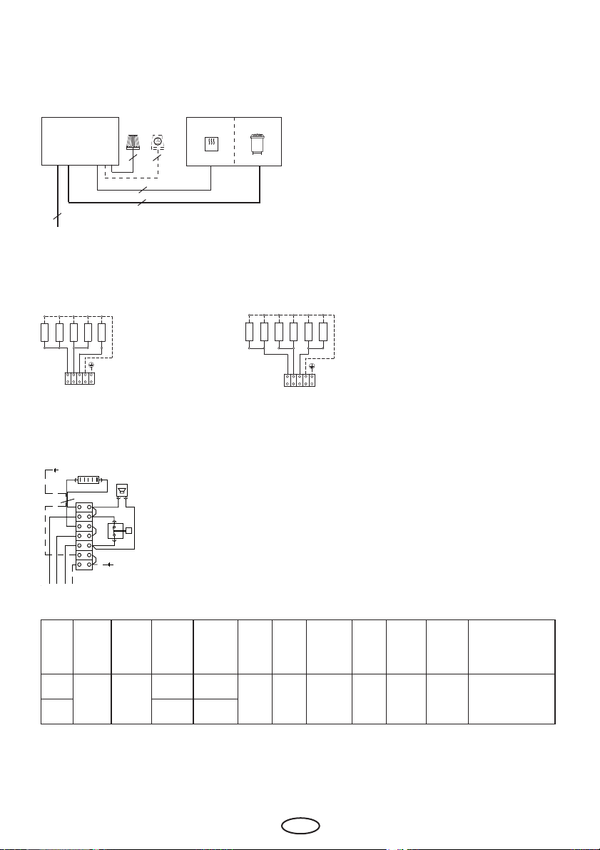
Please note that the highest temperature va-
lues in the cabin always develop in the area
above the sauna heating unit and that the
temperature sensor and safety limiter must
be installed in this area in accordance with
the control unit installation guide.
At the initial heating, you may notice a slight
odor arising from evaporation of substances
from the manufacturing process. Air out your
cabin after this cycle before you begin with
the sauna bath
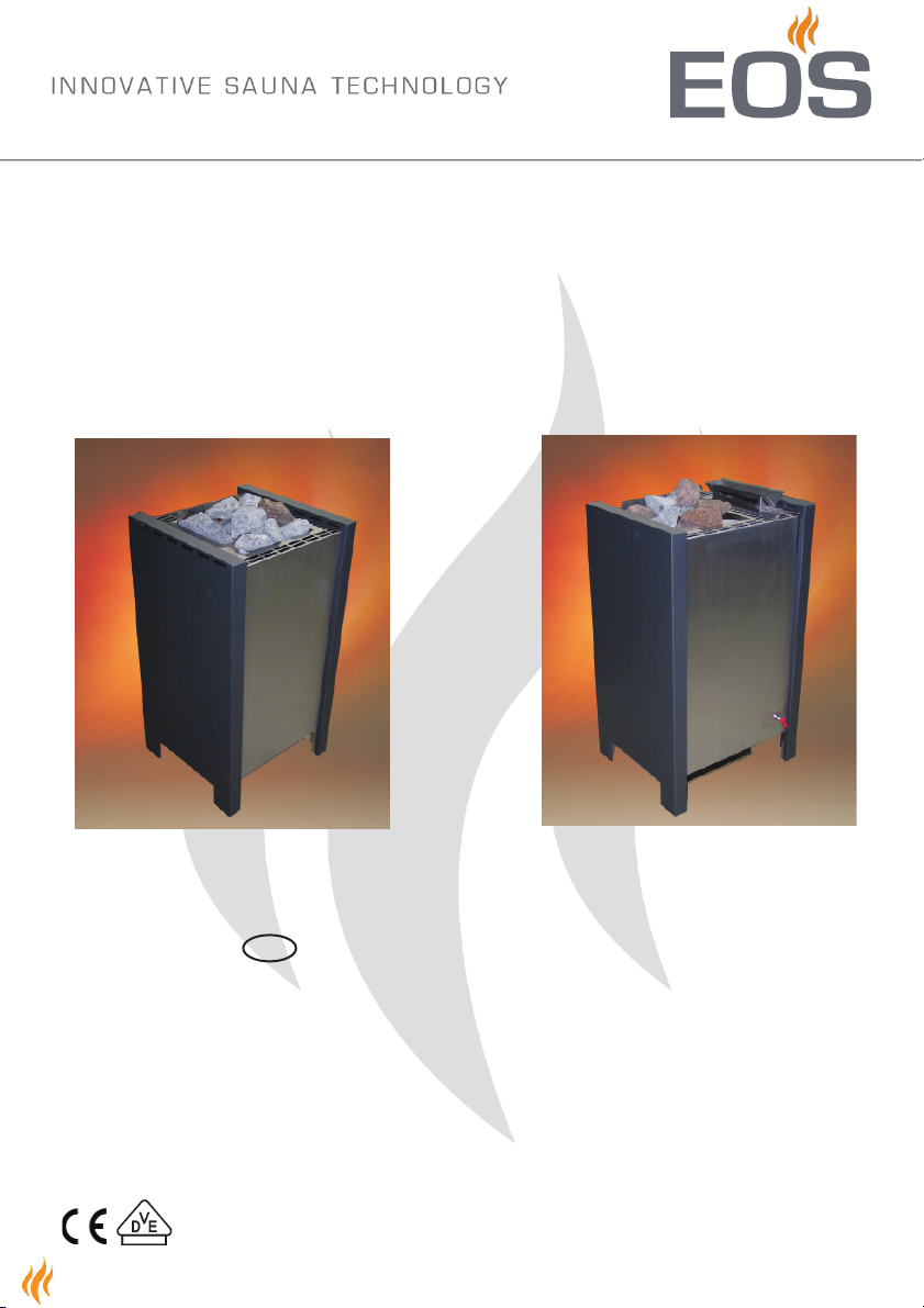
Intended use
This sauna heater is exclusively designed
for the heating of sauna cabins, in connec-
tion with an appropriate control unit.
Any use apart from the defined application
shall be regarded as non-intended use. Ad-
herence to the conventional operating, main-
tenance and servicing conditions is also part
of the intended use.
The manufacturer cannot be made respon-
sible for deviating alterations undertaken on
the authority of the user and any consequen-
tial damage. The risk for such measures
shall be borne solely by the person carrying
out the alterations and causing the damage.
Sauna heaters, with the exception of tho-
se used for household purposes, must be
equipped with a safety device vis-à-vis the
cover per DIN EN 60335-2-53.
As suitable measure, and depending on the
sauna heater, a rocker switch Type I or Type
II may be installed above the heater.
(The rocker switch is not included in the de-
livery scope of the sauna heater.)
For installation and electrical connection of
the rocker switch follow the installation in-
structions supplied with this part.