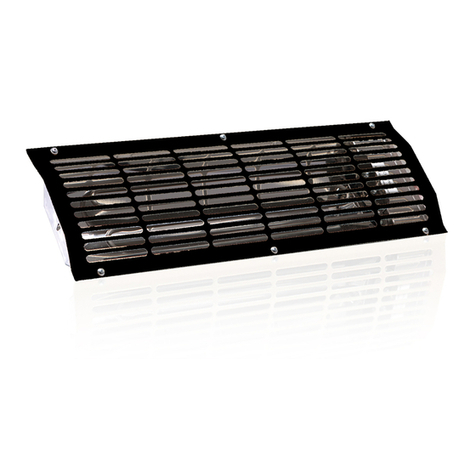
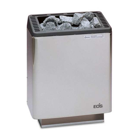
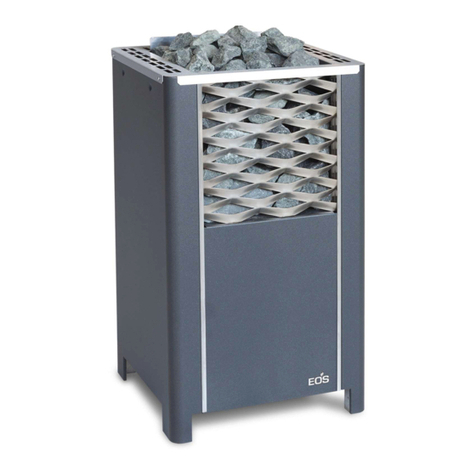
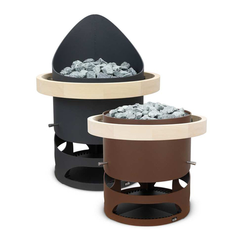
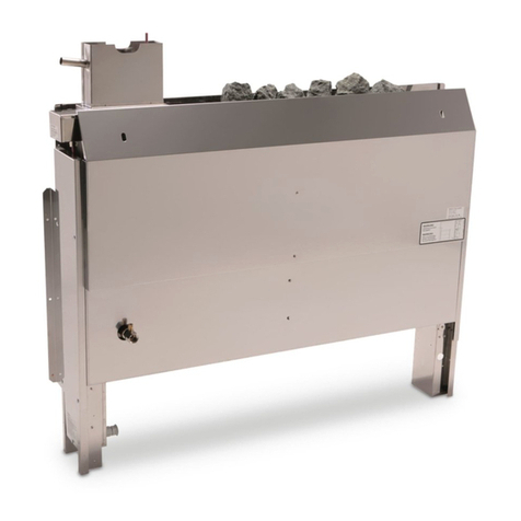
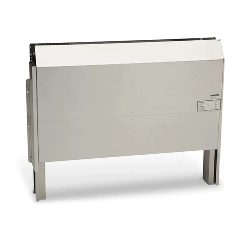
EOS 46.U Planning guide

1
D
MADE IN GERMANY
IP x4 Druck Nr. 29344130 / -15.14
46.U
DMontage- und Gebrauchsanweisung
Assembly and operating instruction
Руководство по монтажу и эксплуатации
GB
RU
Hinterwandofen
Behind-the-bench sauna heater
Печь для скрытого монтажа

15
GB
English
Table of Contents
Intended use .........................................................................................................15
General notes .......................................................................................................15
Important notes.....................................................................................................16
Electrical connection ............................................................................................17
Installation.............................................................................................................19
Technical Data.................................................................................................19
Minimum clearances .......................................................................................19
Mounting of the safety grate............................................................................20
Sauna stones........................................................................................................21
Maintenance and care ..........................................................................................21
Service Address:...................................................................................................23
Guarantee.............................................................................................................23
Handling procedures for return shipments (RMA) - Details for all returns ! ..........24

16 GB
Dear Customer,
You have purchased a high quality technical
appliance which will provide you with many
years of enjoyable sauna bathing. This sauna
heating system was constructed in accordance
with latest European safety standards, inspect-
ed and manufactured in accordance with the
Quality Standard DIN EN ISO 9001:2000.
This detailed installation and user‘s guide was
created for your information. Please note espe-
cially the important information and the detaila
dealing with the electrical connection.
We wish you a richly invigorating and restora-
tive sauna bathing experience.
Intended use
This sauna heater is exclusively designed for
the heating of sauna cabins, in connection with
an appropriate control unit.
Any use apart from the defined application
shall be regarded as non-intended use. Adher-
ence to the conventional operating, mainte-
nance and servicing conditions is also part of
the intended use.
The manufacturer cannot be made responsible
for deviating alterations undertaken on the au-
thority of the user and any consequential dam-
age. The risk for such measures shall be borne
solely by the person carrying out the altera-
tions and causing the damage.
General notes
Please note that an optimal sauna climate can
be reached only when the cabin, with its air in-
take and exhaust, the sauna heating unit and
the control unit have been tuned for compati-
bility with one another.
Please note all data and information provided
by your sauna supplier.
The sauna heating units warm your sauna cab-
in through means of heated air convection. To
this end, fresh air from the air intake vent is
drawn in, rises upon warming (convection) and
is then circulated through the cabin. A part of
the used air is pushed out through the exhaust
vent in the cabin. This is the means by which
the typical sauna climate develops, reaching
characteristic temperatures of about 110° C
directly under the ceiling of your sauna, which
fall off to about 30-40°C in the floor area due
to the temperature gradient in the sauna cabin.
Therefore, it is not unusual when, for example,
temperatures of 110°C prevail in the area of
the temperature sensor over the oven, while
the thermometer, which is installed 20-25 cm
under the cabin ceiling on the sauna wall, reg-
isters only 85° C. With a temperature setting at
maximum, the mean bathing temperature lies
between 80°C and 90°C in the area of the upper
recliner bench.
Please note that the highest temperature val-
ues in the cabin always develop in the area
above the sauna heating unit and that the tem-
perature sensor and safety limiter must be in-
stalled in this area in accordance with the con-
trol unit installation guide.
At the initial heating, you may notice a slight
odor arising from evaporation of substances
from the manufacturing process. Air out your
cabin after this cycle before you begin with the
sauna bath
First of all check whether the sauna heater
has arrived at your site undamaged. Regis-
ter transport damage claims immediately
with the delivering transport company or
please contact the supplier who provided
the equipment to you.
17
GB
Important notes
•
Unprofessional installation may cau-
se a fire hazard! Please read these instal-
lation instructions carefully. In particular,
please observe the dimensions stated and
the following notes.
• This device can be used by children aged
8 upwards and by persons with physical,
sensory, or mental disabilities, or who
have inadequate experience and know-
ledge if they are supervised or if they have
received adequate instruction in how to
use the device safely and understand the
associated risks. Children may not play
with this device. Children may not clean
or carry out any user maintenance if un-
supervised.
• Children should be supervised to make
sure that they will not play with the unit.
• Only specialists may install and con-
nect the sauna heater, control unit and
other electrical equipment with a fixed
mains connection. The necessary protec-
tive measures according to VDE 0100 of §
49 DA/6 and VDE 0100 part 703/2006-2
must be observed.
• Sauna heater and controller may only be
used in sauna cabins made of suitable, low-
resin, untreated materials (e.g. spruce).
• Only a sauna heater with the appropriate
power output may be installed in the sau-
na cabin.
• Please provide air intake and vent ope-
nings in each sauna cabin. The air intakes
must always be positioned behind the
sauna heater, approx. 5 to 10 cm above
the floor. The minimum dimensions of the
air intake and vent openings are stated in
the table.
• The duct vents are always to be positioned
offset diagonally to the sauna heater in
the lower area of the rear sauna wall. The
air intake and vents may not be covered.
Please observe the sauna cabin supplier's
instructions.
• Only the control units specified herein
must be used for the operation of the
sauna heater. This control unit must be
positioned at an appropriate point on the
cabin outer wall; the associated sensor
must be positioned inside the sauna cabin
according to the installation instructions
included with the control unit.
• Caution: Covering the heater or an
incorrectly filled stone container represent
a fire hazard.
• Every time before the sauna is used,
ensure that no objects have been left lying
on the sauna heater.
• Caution: The high sauna heater
temperatures generated during operation
can cause burns.

18 GB
• Do not put the sauna heater into operation
when the air intake is closed.
• The cabin lighting and the corresponding
installation must correspond with the
"splash protected" version in accordance
with DIN EN VDE 0100 T 703. Therefore,
only VDE-tested sauna light with max. 40
Watt may be installed in connection with
the sauna heater.
•
Only a locally certified electrician
may connect the sauna facility (sauna
heater, control unit, lighting etc.) to a fixed
mains connection.
• All electrical installations and all connec-
tion lines that are installed inside the cab-
in must be suitable for an ambient tem-
perature of at least 170 °C. If single-wire
cables are used as connection lines, they
must be protected using a flexible metal
tube connected to the equipment ground-
ing conductor. Please see the table for the
minimum cross-section of the connection
cable and the suitable cabin size in rela-
tion to the power input in kW.
• When installing the sauna heater, please
ensure that the vertical clearance be-
tween the sauna heater upper edge and
the sauna ceiling is maintained. Please
see also the dimensions diagram for the
clearance between the lower edge of the
sauna heater and the floor. On heaters
with bases, this clearance is maintained
via the base or legs of the device.
• Please always ensure that the sauna heat-
er is never placed on flooring made of
flammable material (wood, plastic floor-
ing etc). Ceramic tiles are recommended
as floor materials.
• Floor heating in the sauna cabin increases
the surface temperature of the flooring.
• Please see the dimensions information
for the respective sauna heater for the
clearance between the heater protective
grating or the bench and other flammable
materials. The heater protective grating
must roughly accord with the front height
of the sauna heater.
• Please also observe the information and
instructions provided by the cabin manu-
facturer.
• Please take precautions when
cleaning components with sharp edges.
• Upright heaters need to be fitted on site
with elements that prevent them from
overturning.
• Attention: Pour the infusion water
only on the sauna rocks and never any-
where else.
• When using your sauna in a dry
Finnish mode never add sauna essences or
place any herbs into the vaporizer holder
for essences/herbs. Fire hazard!
• Never add more essences or vol-

19
GB
Electrical connection
Your electrician will be able to accomplish this
work without further explanation in accord-
ance with the provided wiring diagram and
with the help of the circuit diagram mounted
inside the respective control unit.
Be sure to note, however, that live wires should
not be visibly laid onto the inner cabin walls
due to safety considerations. For this reason,
the wall element with the air intake vent is usu-
ally already equipped with cable conduits in
most sauna cabins
Should there be no cable conduits in your cab-
in, drill a hole in the cabin wall immediately
adjacent to the sauna heating unit where the
cable projects from the sauna heating unit and
pull the cable through this hole towards the ex-
terior and then to the control unit. The cable as
well as all other connecting lines (supply wire
to the power source and to the cabin lighting)
on the outside wall of the cabin should also be
protected from damage, for ex. by installation
in cable conduits or by covering with wooden
skirting strips.
Attention!
Dear customer,
according to the valid regulations, the
electrical connection of the sauna heater
and the control box has to be carried out
through the specialist of an authorized
electric shop.
Please be advised that in case of a war-
ranty claim, you are kindly requested to
present a copy of the invoice of the elec-
tric shop which carried out all works.
atile oils than advised on the packaging.
Never use alcohol or undiluted concen-
trates. Caution! Fire hazard!
When designing the cabin ensure that
the external exposed glass surfaces only re-
ach a maximum temperature of 76°C. If ne-
cessary, protective features need to be fit-
ted.

20 GB
CAUTION! Make sure the
neutral wire is connected.
Wiring diagrams
Power Electrical.
Connection
Fuse control
unit in A Fuse LSG in A
Connecting
cable main -
control unit in
mm²
Connecting
cable main -
LSG in mm²
Connecting
cable control
unit - heater in
mm²
Connecting
cable LSG -
heater in mm²
Connecting
cable control
unit - LSG in
mm²
6,0 kW
3N AC
50 Hz
400 V
3 x 16 5 x 2,5² 5 x 1,5²
7,5 kW
9,0 kW
12,0 kW 3 x 16 5 x 2,5² 5 x 1,5² 4 x 1,5²
All cross sections of a line are minimum diameters in mm² (Copper line)
Power Dimensions
H/W/D cm For cabin size
Minimum
dimensions of
air intake and
exhaust vents
Weight
without stones
without
package
Stone filling
Power switch
gear (LSG)
needed
For operation with control units
6,0 kW
87 / 112 / 20
6 - 8 m³ 35 x 4 cm 23,5 kg
15 kg
ECON D1, D2, D3
ECON H1, H2, H3
EMOTEC D
EMOTEC H
EmoTouch II +
7,5 kW 7 - 10 m³ 35 x 5 cm 25,0 kg
9,0 kW 9 - 14 m³ 35 x 6 cm
24,5 kg
12,0 kW 14 - 18 m³ 35 x 7 cm ECON L09
EMOTEC L09
6000 W
1500 W
1500 W
1500 W
1500 W
U V W N
7500 W
1500 W
1500 W
1500 W
1500 W
1500 W
U V W N
9000 W
1500 W
1500 W
U V W N
1500 W
1500 W
1500 W
1500 W
12000 W
1500 W
1500 W
U V W N
1500 W
1500 W
1500 W
1500 W
1500 W
1500 W
U V W N

21
GB
Installation
Technical Data
Voltage: 400 V AC 3N 50 Hz
Power rating: 6.0; 7,5;9,0;12,0 kW depen-
ding on the version
Height: 870
Width: 1120 mm
Depth: 200 mm
Rock store: 15 kg
Leakage current: max. 0.75 mA per kW
heating capacity
Sauna oven for use in domestic and com-
mercial sauna cabins
Standard delivery includes:
1 sauna oven
1 safety grill, wooden funnel and silicone
pipe
4 screws
1 box sauna rocks
The sauna oven is intended for a connec-
tion voltage of 400 V AC 3 N via a sauna
controller.
The minimum height of the sauna cabin must
be 1.90 m on the inside.
When assembling the sauna oven, attention
must be paid to the fact that the vertical di-
stance between the upper edge of the oven
and the sauna roof must be at least 90 cm,
and the horizontal (lateral) distance between
the oven and the booth wall at least 7cm
The distance between the oven protective gril-
le and the sauna bench or other combustible
materials must be at least 2 cm from the oven.
The provided safety grate has to be installed
above the oven at the upper edge of the
partition to the rear wall. Care should be
taken, that objects do not accidentally fall onto
the heater.
Minimum clearances
200
70
Fig. 1
safety grill
Fig. 2
* for cubicles up to 2 x 2 m
** for bigger cubicles
air
intak
Maße in mmAll
dimensions in mm
200
min. 300
1030
870
170
Heater safety
grate
Fig. 2a
air intak
220
min. 300
1030
870
170
200
70
Contradictory to the advice concerning the
mounting of the sensor of your sauna control
unit, the heater sensor shall not be mounted
centrically above the sauna heater but, as
shown in the diagram.
te mp er at ur e
sensor
heater sensor
190*
390** 190*
390**
730

22 GB
Attach a warning sign near the water
funnel
Fig. 3
1120
700170
200
Mounting of the safety grate
s t o n e
basket
water pan
water funnel
e l b o w
pipe
Fig. 4
silicontube
Attention!
The infusion effect occurs retar-
ded. Pour out the ladle into the funnel
tube in the cabin.
Then, the water is led across the sauna
rocks in the oven by the silicone connecting
hose and evenly distributed over the rocks
by the infusion bowl.
Now, with the hot ascending water, the
water steam is constantly spread out in the
cabin and, thus, leads to a pleasant infusion
feeling.
Remember that the sauna rocks must
heat up again after each infusion in order
to produce an intensive steam. Therefore,
wait approximately 8 to 10 minutes for the
next infusion.

23
GB
Please be sure to note!
Do not insert sauna rocks too tightly in
the rock store. Place them loose, leaving
as many spaces as possible to allow the
free flow of hot air for circulation purpo-
ses.
Remove stones from the sauna heater
only when they cooled down.
It cannot be excluded that hot rocks
or their parts fall out of the rock store.
Risk of fire!
Sauna stones are a natural product. Check the
sauna stones at regular intervals. Aggressive
sauna essensces can weaken the sauna stones
and cause them to break apart over time. Con-
sult your sauna supplier if necessary.
Rinse the sauna stones provided under running
water and then place them in the stone com-
partment so that the convection air flow can
circulate easily between the stones (Illust. 9 +
10).
The quantity of stones is sufficient to create a
steam shock, vaporizing about 10 cl of water
per m³ cabin volume. Always wait 10 minutes
after infusion before repeating the infusion.
Only then the sauna stones will re-heat suffici-
ently again.
!
!
!
!
!
!
!
!
!
!
!
!
!
!
!
!
!
!
!
Never add more essences or volatile
oils than advised on the packaging. Never
use alcohol or undiluted concentrates. Cau-
tion! Fire hazard!
All sauna heating units are made of low-corro-
sion material. To enjoy your sauna heating unit
for a long time you should ensure maintainance
and take due care about the heater. Always
make sure that the air supply vents and reflec-
tion surfaces in the area of air intake are free.
These can easily become clogged with fuzz and
dust when drawing in fresh air. This reduces the
air convection in the sauna heating unit and
can be a cause of too high temperatures.
Clean or de-scale the heater when needed.
Refer to your sauna supplier or directly to the
manufacturer in case of defects or signs of wear
and tear.
Only use original manufacturer‘s replacement
parts, which can be obtained from your sup-
plier or directly from the manufacturer.
If you did not use your sauna for a long period
of time, always check before next use that clo-
ths, cleansers or other objects have not been
left on the sauna heating unit or the vaporizer
before turning them on.
Sauna rocks Maintenance and care

24 GB
For the installation of sauna heaters, please
pay attention to the DIN VDE 0100 part 703 !
This standard makes the following statement
valid in your newest expenditure, since Februa-
ry 2006, paragraph 703.412.05; Quotation:
The additional must be planned for all electric
circuits of the Sauna by one or more fault current
protection device (RCDs) with a calculation diffe-
rence stream not more largely than 30 mA, exclu-
ded of it is Sauna heating.
The EN 60335-1 DIN VDE 0700 part 1 of Janu-
ary 2001 states the following in paragraph 13;
quote:
The leakage current may not exceed the following
values during operation:
- for stationary heaters of protection class I 0,75
mA; or 0,75 mA each kW input of the appliance,
depending on the higher value, at a maximum
value of 5 mA.
If the appliance is equipped with a protective
device for leakage current (ELCB), please pay at-
tention to the fact that no other electrical units
will be protected by this ELCB.
Under current manufacturing technology, it is
not reasonable to use heating elements for sau-
na heaters which do not collect moisture from
the surrounding air. It is therefore possible that
a little bit of moisture from the surrounding air
may reach the magnesium-oxide filling in the
heating elements during transport or storage
and may cause the ELCB to release.
In this case the oven must be heated up under
supervision of an expert, during which the PE
conductor is not connected. After about 10
minutes, when moisture has evaporated from
the heating elements, the oven must be recon-
nected to the PE conductor!
If the sauna heater is not in use for a significant
period of time, we recommend running it every
6 weeks, so as to avoid moisture concentrating
in the heating elements.
Therefore, should the ELCB be released during
start-up, the electrical installation must be che-
cked.
Installation of the sauna heater and control
unit must be undertaken only by an authorized
electrician. Without a documented proof of
such installation a warranty is generally void.

Service Address:
EOS Saunatechnik GmbH
Schneiderstriesch 1
35759 Driedorf, Germany
Tel: +49 (0)2775 82-514
Fax: +49 (0)2775 82-431
servicec[email protected]
www.eos-sauna.de
WARRANTY
The warranty is provided according to the legal
regulations at present.
Manufacturer’s guarantee:
- The period of guarantee starts from the date
of purchase and lasts up to 2 years by com-
mercial use and 3 years by private use.
- Always include the completed guarantee cer-
tificate when returning equipment.
- The guarantee is void for appliances which
have been modified without manufacturer’s
explicit agreement.
- Damages caused by incorrect operation or
handling through non-authorized persons
are not covered under the terms of guarantee.
- In the event of a claim please indicate the se-
rial number as well as the item number and
model name with detailed description of the
fault.
- This guarantee covers defective parts and la-
bour but not the defects caused by wear and
tear.
In case of complaint please return the equip-
ment in its original packaging or other suitable
packaging (caution: danger of transport dam-
age) to our service department.
Always include the completed warranty certifi-
cate when returning equipment.
Possible shipping costs arising from the trans-
port to and from point of repair cannot be over-
taken by us.
Outside of Germany please contact your spe-
cialist dealer in case of warranty claims. Direct
warranty processing with our service depart-
ment is in this case not possible.
Equipment commissioning date:
Stamp and signature of the authorized elec-
trician:
Please keep this address in a safe place togeth-
er with the installation guide.
To help us answer your questions quickly and
competently please provide the information
printed on the type shield including the model,
item no. and serial no., in all inquiries.
25
GB

Dear customer
we hope that you will be satisfied with the purchased EOS product. In the rear case if you
may have a claim and will need to return a product, please follow the procedures specified
below. This will enable to ensure a quick and effective handling of the return shipment.
Reason of complaint and proceedings:
Please observe for all returns!
• Please add the provided RMA-voucher completely filled out together with an invoice
copy to the return shipment! Do not stick it on the goods or on the packaging. We do not
accept return shipments without these papers.
• Not prepaid parcels will be refused and returned to Sender! Please always ask your dealer or
EOS service department about the most economical return shipment way.
• Please pay attention that the goods have to be sent back in the original scope of delivery
and in original packing.
• We recommend to use an additional solid and break-proof covering box which should be
padded out with styrofoam, paper or similar. Transport damages as a result of faulty packing
are for the sender‘s account.
2) Faulty goods
• The implied warrenty pe-
riod is 2 years.Please con-
tact your dealer in case of
faulty or wrong articles
or missing accessories.
He will discuss with you
the individual case and
try for immediate and
customer-friendly solu-
tion.
• For economic returns
within Germany you will
get an RMA-number
from the manufacturer.
• All returns have to be in
the original packing of
the goods with corre-
sponding accessories.
Please repack the goods
to avoid damages. In case
of wrong delivery, please
do not use this article .
3) Problems of installa-
tion and functioning
• Please read the manual
carefully first of all and
pay attention to the indi-
cated assembly or install-
ing instructions.
• Your dealer should be
the first contact person
because he knows his
products best and also
knows possible prob-
lems.
• In case of function
problems with an ar-
ticle, please check at
first whether there is an
obvious material defect.
The quality system in our
factory reduces malfunc-
tions of new appliances
to almost zero.
1) Transportation damage
• Please check the content
of your parcel imme-
diately and advise the
forwarding company of
a claim (parcel service/
freight forwarder)
• Do not use damaged
goods!
• Ask the forwarder for a
written acknowledge-
ment of the damages.
• Report the claim
promptly by phone to
your dealer. He will dis-
cuss with you how to act
in this case.
• If the transport box has
been damaged, please
use an additional cover-
ing box. Do not forget to
add the acknowledge-
ment of the damage of
the forwarding compa-
ny !
Handling procedures for return shipments (RMA) - Details for all returns !
26 GB
Other manuals for 46.U
3
Table of contents
Other EOS Heater manuals

EOS
EOS Zeus S User manual

EOS
EOS IRS 35 RHK Planning guide

EOS
EOS Bi-O Invisio Planning guide

EOS
EOS 38.AS Installation guide

EOS
EOS Cubo 2 User guide

EOS
EOS IRS 40 RHK Planning guide

EOS
EOS IRS 35 Planning guide

EOS
EOS Herkules XL S50 Planning guide

EOS
EOS Herkules XL S120 Planning guide

EOS
EOS Invisio Midi Planning guide