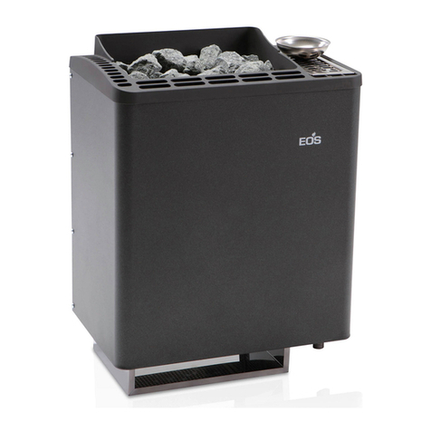
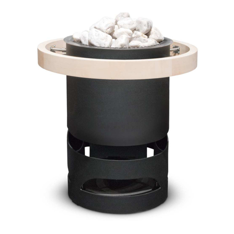
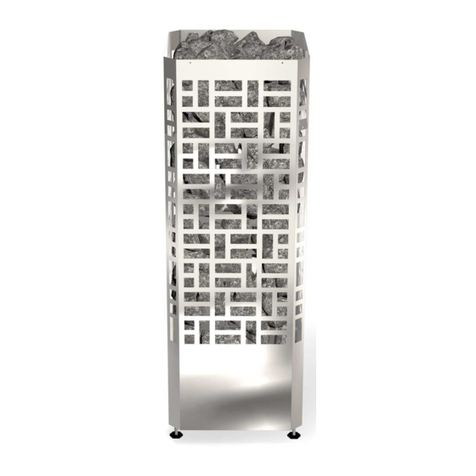
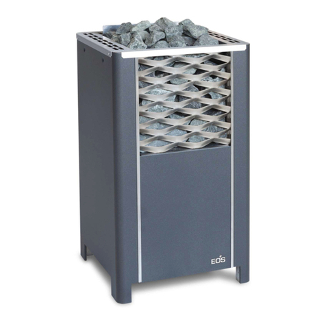
EOS Herkules XL S120 Planning guide

1
D
Herkules XL S120 vapor
IPx4
Made in Germany
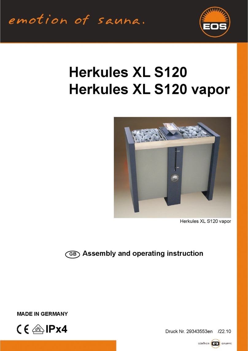
Herkules XL S120
Herkules XL S120 vapor
Druck Nr. 29343553en-ru / 27.17
EN Assembly and operating instruction
Руководство по монтажу и эксплуатации
RU

2
English.......................................................................................3
Русско .....................................................................................24

3
EN
English
Table of Contents
Intended use..................................................................................................................................................4
General notes................................................................................................................................................4
Important notes...........................................................................................................................................5
Electrical connection .................................................................................................................................6
Installation......................................................................................................................................................8
Minimum clearances...........................................................................................................................8
Positioning of sensor ..........................................................................................................................8
Installation......................................................................................................................................................9
Electrical connection............................................................................................................................... 11
Herkules XL S120 18 kW .................................................................................................................11
Herkules XL S120 vapor 18 kW.....................................................................................................12
Herkules XL S120 24 kW .................................................................................................................13
Herkules XL S120 vapor 24 kW.....................................................................................................14
Herkules XL S120 30 kW ................................................................................................................15
Herkules XL S120 vapor 30 kW.....................................................................................................16
The water connection............................................................................................................................. 17
De-scaling of the vaporizer...................................................................................................................17
Assembly of the protective cover on the sauna heater ......................................................18
Finnish sauna operation......................................................................................................................... 19
Operation with vaporizer....................................................................................................................... 19
Sauna stones .............................................................................................................................................. 20
Maintenance and care ............................................................................................................................ 20
Service Address: ........................................................................................................................................22
Guarantee.................................................................................................................................................... 22
General Terms and Conditions of Service..................................................................23

4EN
Dear customer
You have purchased a high-quality technical
device with which you will have years of sauna
fun.This sauna heater was designed and inspect-
ed according to the current European safety
standards and manufactured at the factory
in accordance with the quality management
standard DIN EN ISO 9001:2008.
This detailed installation and operation manual
has been prepared for your information. Please
observe in particular the important notes and
the information on electrical connection.
We wish you exhilarating recreational experience
and lots of fun with your sauna!
Intended use
This sauna heater is exclusively intended for the
heating of sauna cabins in combination with an
appropriate control unit.
Any other use over and above the intended
purpose is not considered as appropriate use!
Compliance of the standard operation, mainte-
nance and repair conditions is also an element
of appropriate use.
The manufacturer cannot be held liable for
deviating, unauthorized alterations and any re-
sulting damages: the initiator of these changes
bears the full risk.
General information
Please check whether the unit has arrived in per-
fect condition. Any transport damages should be
immediately reported to the freight forwarder
delivering the goods or you should contact the
company that shipped the goods.
Please note that you will only be able to achieve
an optimum sauna climate if the cabin with its air
intake and ventilation, the sauna heater and the
control unit are aligned to each other.
Please observe the information and stipulations
made by your sauna supplier.
Sauna heaters heat up your sauna cabin using
heated convective air. Here, fresh air is drawn
in from the air intake which, when heated, rises
upwards (convection) and is then circulated
within the cabin. Part of the used air is pushed
out through the vent in the cabin.This creates a
typical sauna climate which can achieve temper-
atures of approx. 110°C measured directly under
the ceiling of your sauna, dropping in temper-
ature to approx. 30-40°C towards the oor. It is
therefore not unusual to measure temperatures
of 110°C on the temperature sensor hanging
over the heater, whilst the thermometer hanging
on the sauna wall, approx. 20-25 cm under the
cabin ceiling, only indicates 85°C. The bathing
temperature generally lies between 80°C and
90°C in the area of the upper bench when the
temperature is set to maximum.
Please note that the highest temperatures are
always generated over the sauna heater and that
the temperature sensor and the safety limiter
must be mounted there in accordance with the
control unit installation instructions.
When heating up for the first time, you may
notice a slight smell caused by evaporating
lubricants used in production processes. Please
ventilate your cabin before beginning your
sauna bath.

5
EN
Important notes
• Unprofessional installation may
cause a re hazard! Please read these in-
stallation instructions carefully. In particu-
lar, please observe the dimensions stated
and the following notes.
• This device can be used by children aged
8 upwards and by persons with physical,
sensory, or mental disabilities, or who
have inadequate experience and knowl-
edge if they are supervised or if they have
received adequate instruction in how to
use the device safely and understand the
associated risks. Children may not play
with this device. Children may not clean
or carry out any user maintenance if un-
supervised.
• Children should be supervised to make
sure that they will not play with the unit.
• Only specialists may install and con-
nect the sauna heater, control unit and
other electrical equipment with a xed
mains connection. The necessary protec-
tive measures according to VDE 0100 of §
49 DA/6 and VDE 0100 part 703/2006-2
must be observed.
• Sauna heater and controller may only be
used in sauna cabins made of suitable,
low-resin, untreatedmaterials(e.g. spruce).
• Only a sauna heater with the appropriate
power output may be installed in the sau-
na cabin.
• Please provide air intake and vent open-
ings in each sauna cabin. The air intakes
must always be positioned behind the
sauna heater, approx. 5 to 10 cm above
the oor. The minimum dimensions of the
air intake and vent openings are stated in
the table.
• The duct vents are always to be positioned
oset diagonally to the sauna heater in
the lower area of the rear sauna wall. The
air intake and vents may not be covered.
Please observe the sauna cabin supplier's
instructions.
• Only the control units specied here-
in must be used for the operation of the
sauna heater. This control unit must be
positioned at an appropriate point on the
cabin outer wall; the associated sensor
must be positioned inside the sauna cabin
according to the installation instructions
included with the control unit.
• Caution: Covering the heater or an
incorrectly lled stone container represent
a re hazard.
• Every time before the sauna is used,
ensure that no objects have been left lying
on the sauna heater.
• Caution: The high sauna heater
temperatures generated during operation
can cause burns.
• The sauna heater is not intended for in-

6EN
stallation or set-up in a niche, under a
bench or under a sloping roof.
• Do not put the sauna heater into operation
when the air intake is closed.
• The cabin lighting and the corresponding
installation must correspond with the
"splash protected" version in accordance
with DIN EN VDE 0100 T 703. Therefore,
only VDE-tested sauna light with max. 40
Watt may be installed in connection with
the sauna heater.
• Only a locally certied electrician
may connect the sauna facility (sauna
heater,controlunit,lighting etc.)to axed
mains connection.
• All electrical installations and all connec-
tion lines that are installed inside the cab-
in must be suitable for an ambient tem-
perature of at least 170 °C. If single-wire
cables are used as connection lines, they
must be protected using a exible metal
tube connected to the equipment ground-
ing conductor. Please see the table for the
minimum cross-section of the connection
cable and the suitable cabin size in rela-
tion to the power input in kW.
• When installing the sauna heater, please
ensure that the vertical clearance be-
tween the sauna heater upper edge and
the sauna ceiling is maintained. Please
see also the dimensions diagram for the
clearance between the lower edge of the
sauna heater and the oor. On heaters
with bases, this clearance is maintained
via the base or legs of the device.
• Please always ensure that the sauna heat-
er is never placed on ooring made of
ammable material (wood, plastic oor-
ing etc). Ceramic tiles are recommended
as oor materials.
• Floor heating in the sauna cabin increases
the surface temperature of the ooring.
• Please see the dimensions information
for the respective sauna heater for the
clearance between the heater protective
grating or the bench and other ammable
materials. The heater protective grating
must roughly accord with the front height
of the sauna heater.
• Please also observe the information and
instructions provided by the cabin manu-
facturer.
• Please take precautions when
cleaning components with sharp edges.
• Upright heaters need to be tted on site
with elements that prevent them from
overturning.
• Attention: Pour the infusion water
only on the sauna rocks and never any-
where else.
• When using your sauna in a dry
Finnish mode never add sauna essences or

7
EN
place any herbs into the vaporizer holder
for essences/herbs. Fire hazard!
• Never add more essences or vol-
atile oils than advised on the packaging.
Never use alcohol or undiluted concen-
trates.Caution! Fire hazard!
• When designing the cabin ensure
that the external exposed glass surfaces
only reach a maximum temperature of
76°C. If necessary, protective features
need to be tted.
Caution!
Dear Customer,
In compliance with the valid regulations,
only certied electricians may connect the
sauna heater and the sauna control system
to the mains power supply. Please note
that you must provide a copy of the invoice
from the electrical company who installed
the sauna in case of a warranty claim.
Electrical connection
Using the above-mentioned wiring diagram
and the information on the wiring circuit ad-
hered to the respective control system, your
electrician will be able to connect the system
without further instructions.
Please note that, for safety reasons, power ca-
bles may not be laid visibly on the interior walls
of the cabin. Most sauna cabins have empty
ducts tted into the wall element with the air
intake.
If no empty ducts are available in your cabin,
drill a suciently sized hole in the cabin wall
directly next to the place where the cable exits
the sauna heater and guide this cable outside
through the hole to the control unit. The cable,
and all other connecting cables (mains power
cables and cabin lighting), should be installed
in installation ducts or also be protected against
damage on the outside of the cabin e.g. by lay-
ing them in installation pipes or attaching wood
cover strips.
The sauna heater, if used in commercial/public
facilities and equipped with remote control*,
may be used only in combination with the ap-
propriate cover protection system or S-Guard
system.
*Remote control – means settings, switching, control
and adjustment of the sauna control unit by means of
commands transmitted from a remote location beyond
sight distance using telecommunication, wire- or wire-
less signal transmission systems, network and similar
systems.

8EN
The scope of delivery should include:
1 sauna heater
8 sets of sauna rocks supplied in fabric bags
1 aroma bowl, 1 stand for the aroma bowl
1 accessory bag containing the warning plate
and 2 bolts (4.2 x 9.5)
Technical data
Voltage: 400 V AC 3N 50 Hz
Power consumption: 18,0 24,0 or 30,0 kW
according to model
Vaporizer: only Herkules vapor XL
3 /4 kW
Height: 850 mm
Width:960 mm
Depth: 530 mm
Filling capacity for stones: 120 kg
Weight: 85 kg (without packaging)
Stray current: max. 0,75 mA per kW heating
capacity
Sauna oven for use in commercial saunas
The warning sticker is to be x viewable in
the near of the sauna heater.
Capacity
acc. DIN
Electrical.
Connection
Fuse control
unit in A Fuse LSG in A
Connecting cable
main - control
unit in mm²
Connecting
cable main -
LSG in mm²
Connecting cable
control unit -
heater in mm²
Connecting cable
LSG - heater
in mm²
Connecting cable
control unit - LSG
in mm²
18 kW
3N AC
50 Hz
400V
3 x 16 3 x 16 5 x 2,5 5 x 2,5 5 x 1,5
4 x 1,5 5 x 1,5 4 x 1,5
24 kW 3 x 16 3 x 35 5 x 2,5 5 x 6 5 x1,5
3 x 1,5
5 x 4
4 x 2,5 5 x 1,5
30 kW 1 x 16 3 x 63 3 x 1,5 5 x 16 3 x 1,5 2 St. 5 x 4
1 St. 4 x 2,5 6 x 1,5
All cross sections of a line are minimum diameters in mm² (Copper line)
Herkules XL S120 vapor
Capacity
acc. DIN
Electrical.
Connection
Fuse control
unit in A Fuse LSG in A
Connecting cable
main - control
unit in mm²
Connecting cable
main - LSG in mm²
Connecting cable
control unit -
heater in mm²
Connecting cable
LSG - heater in mm²
Connecting cable
control unit - LSG
in mm²
18 kW 3N AC
50 Hz
400V
3 x 16 3 x 16 5 x 2,5 5 x 2,5 5 x 1,5 5 x 1,5
4 x 1,524 kW 3 x 35 5 x 6 5 x 4
30 kW 1 x 16 3 x 63 3 x 1,5 5 x 16 2 St. 5 x 4
All cross sections of a line are minimum diameters in mm² (Copper line)
Herkules XL S120
Capacity
acc. DIN
Installation
dimensions
H/W/D cm
For cabin size
Minimum dimensions
of air intake and
exhaust vents
Weight without stones
without package Stone lling Power switch
gear needed
For operation with
control units
18 kW
85 x 96 x 53
24 - 35 m³ 50 x 6 cm
ca. 85 kg 2 x 60 kg
EMOTEC L09R EMOTEC-series
EmoStyle-series
EmoTouch-series
24 kW 35 - 45 m³ 50 x 8 cm LSG 18
30 kW 45 - 65 m³ 50 x 10 cm LSG 36
Capacity
acc. DIN Vaporicer
Installation
dimensions
H/W/D cm
For cabin size
Minimum
dimensions of
air intake and
exhaust vents
Weight without
stones without
package
Stone lling Power switch
gear needed For operation with control units
18 kW 3 kW
85 x 96 x 53
24 - 35 m³ 50 x 6 cm
ca. 85 kg 2 x 60 kg
EMOTEC L09R EMOTEC H
EmoStyle H/Hi
EmoTouch-series
24 kW 4 kW 35 - 45 m³ 50 x 8 cm LSG 18H
30 kW 45 - 65 m³ 50 x 10 cm LSG 36H

9
EN
Installation
Caution: remove the side panes
for transporting without a euro pal-
let!!!
(It is not possible to carry the sauna heater by
lifting and holding the side panes.)
Loosen the 4 visible screws on each side panel.
Following the alignment of the sauna heater,
remove any remaining protective lm and re-
mount the side panes.
Adjustment and displacement of the sauna he-
ater when it is lled with rocks is not possible.
Minimum clearances
96 cm
8 cm 8 cm
8 cm 8 cm
53 cm
Fig. 1
• The minimum height of the sauna cabin must
be 2.10 m on the inside.
• During the installation of the sauna heater en-
sure that the vertical clearance between the
top edge of the sauna heater and the roof of
the sauna cabin is at least 125 cm and that
the horizontal (lateral) clearance between
the heater and the cabin wall is at least 8 cm.
Positioning of sensor
8 cm
8 cm
min. 125 cm
ca.51 cm
ca. 85 cm
Cabin wall
Cabin roof
Rock
basket
inclined
to the
wall
Contradictory to the specications concerning
the mounting of the sensor of your sauna con-
trol unit, the heater sensor is not mounted cen-
trically above the sauna heater but, as shown
in the diagram, above the rock basket inclined
towards the side wall of the cabin.
• The clearance between inammable materials
and the sauna heater must be at least 8 cm.
• The wooden rail is no substitute for a safety
barrier for protection against accidental
contact. A suitable safety barrier should be
provided by the manufacturer of the cabin
according to the individual situation of in-
stallation
The sauna heater, if used in commercial/public
facilities and equipped with remote control*,
may be used only in combination with the ap-
propriate cover protection system or S-Guard
system.
*Remote control – means settings, switching,
control and adjustment of the sauna control
unit by means of commands transmitted from a
remote location beyond sight distance using tel-
ecommunication, wire- or wireless signal trans-
mission systems, network and similar systems.

10 EN
Water level con-
trol for vaporizer
Terminal box for
vaporizer
Terminal box for
heating coils
Screw the connection hose of the
vaporizing bowl to the bottom t-
ting of the water level control
A plunger (1) opens or closes the volve (2), so
that you can be sure your container is always
full.
(only Herkules XL S120 vapor)
(only Herkules XL
S120 vapor)
(only Herkules
XL S120 vapor)
Installation
(1)
(2)
water level
~720 mm
rear side Herkules XL S120 Vapor

11
EN
1,0 kW
1,0 kW
1,0 kW
1,0 kW
1,0 kW
1,0 kW
1,0 kW
1,0 kW
1,0 kW
1,0 kW
1,0 kW
3
1,0 kW
1,0 kW
1,0 kW
1,0 kW
1,0 kW
1,0 kW
2 1
1,0 kW
5 4 3 2 1
N V
W
U
zum Steuergerät 9 kW
to control unit
zum Leistungsschaltgerät 9 kW
to power control unit
5 466
2 2 2
N
W
1 1
V
1
U
18 kW
1,33 kW
1,33 kW
1,33 kW
3 2 1
1,33 kW
1,33 kW
1,33 kW
1,33 kW
1,33 kW
1,33 kW
1,33 kW
1,33 kW
1,33 kW
1,33 kW
1,33 kW
1,33 kW
1,33 kW
1,33 kW
1,33 kW
5 4 3 2 1
N V
W
U
5 466
2 2 2
N
W
1 1
V
1
U
24 kW
zum Steuergerät 8 kW
to control unit
zum Leistungsschaltgerät 16 kW
to power control unit
zum Leistungs-
schaltgerät 36 kW
to power control unit
1,66 kW
1,66 kW
1,66 kW
1,66 kW
1,66 kW
1,66 kW
1,66 kW
1,66 kW
1,66 kW
1,66 kW
1,66 kW
3
1,66 kW
1,66 kW
1,66 kW
1,66 kW
1,66 kW
1,66 kW
2 1
1,66 kW
30 kW
5 4 3 2 1
N V
W
U
5 466
2 2 2
N
W
1 1
V
1
U
15 kW
15 kW
5 x 4 2
5 x 4 2
Heizstab-Verdampfer
heating element water
bl
max. 1,5 kW
max. 1,5 kW
buzzer
Summer
Thermal
cut-out
Thermostat-
Verdampfer
bl
Anschluß Steuerung
to control unit
Wm
N
PE
Wb
N
L
DruckNr.: 29343597-2 38.11
3 kW
Heizstab-Verdampfer
heating element water
bl
max. 2 kW
max. 2 kW
buzzer
Summer
Thermal
cut-out
Thermostat-
Verdampfer
bl
Anschluß
Leistungsschaltgerät
Anschluß
Steuerung
to power control unitto control unit
Wm
N
PE
Wb
N
LV2
LV1
only
Herkules XL
S120 vapor

12 EN
Electrical connection
Herkules XL S120 18 kW Caution! Always include the
neutral line N in the connec-
tion
400 V AC 3N
N U V W
U V W N L1 L2 L3 N
S1 V N
400 V AC 3N
fan light
L N L N
L1 L2 L3 N W V U N N
WB
WM
3 4
S1
S1 N
STB
Saunasteuergerät / Control unit /
Boîtier de commande / Пульт управления
LSG
Contactor box
Saunaofen
Sauna heater
Sensorbus
Saunabus
reserviert
N U V W
1 1 1 1
Sensor
Limiter
LSG
5 5
5
4
5
4
Saunasteuergerät
Control unit
Boîtier de commande
Пульт управления
Saunaheizgerät
Sauna heater
Poêle de sauna
Печь для сауны
Leistungsschaltgerät
Power extension unit
Extension de puissance
Блок расширения мощности
Netz / Mains / Réseau / Сеть

13
EN
Herkules XL S120 vapor 18 kW Caution! Always include the
neutral line N in the connec-
tion
400 V AC 3N
WB WM N
max. 3 kW
U V W N L1 L2 L3 N
S1 V N
400 V AC 3N
fan light
L N L N
L1 L2 L3 N W V U N N
WB
WM
3 4
S1
S1 N
STB
Saunasteuergerät / Control unit /
Boîtier de commande / Пульт управления
LSG
Contactor box
Saunaofen
Sauna heater
Verdampfer
Vaporizer
Sensorbus
Saunabus
reserviert
N U V W N U V W
1 1 1 1
Sensor
Limiter
4
Saunasteuergerät
Control unit
Boîtier de commande
Пульт управления
Saunaheizgerät
Sauna heater
Poêle de sauna
Печь для сауны
5
5
Netz / Mains / Réseau / Сеть
3
4
optional
5
5
4
LSG
Leistungsschaltgerät
Power extension unit
Extension de puissance
Блок расширения мощности

14 EN
Herkules XL S120 24 kW Caution! Always include the
neutral line N in the connec-
tion
LSG
5 5
5
4
5
4
Saunasteuergerät
Control unit
Boîtier de commande
Пульт управления
Saunaheizgerät
Sauna heater
Poêle de sauna
Печь для сауны
Leistungsschaltgerät
Power extension unit
Extension de puissance
Блок расширения мощности
Netz / Mains / Réseau / Сеть
400 V AC 3N
N U V W
U V W N L1 L2 L3 N
S1 V N
400 V AC 3N
fan light
L N L N
L1 L2 L3 N W V U N N
WB
WM
3 4
S1
S1 N
STB
Saunasteuergerät / Control unit /
Boîtier de commande / Пульт управления
LSG
Contactor box
Saunaofen
Sauna heater
Sensorbus
Saunabus
reserviert
N U V W
1 1 1 1
Sensor
Limiter

15
EN
Herkules XL S120 vapor 24 kW Caution! Always include the
neutral line N in the connec-
tion
LSG 18 H
34
5 5
5
5
5
43
optional
Netz / Mains / Réseau / Сеть
Saunasteuergerät
Control unit
Boîtier de commande
Пульт управления
L1 L2 L3 N
Sensor
Limiter
S1 U V W Wb Wm N
400 V AC 3N
4 3 2 1
Sensor
LV2Wb N Wm LV1 4 3 2 1 U V W N L1 L2 L3 N
S1 V N
400 V AC 3N
Wm N LV1LV2N
LSG 18 H
Saunasteuergerät / Control unit /
Boîtier de commande / Пульт управления

16 EN
Herkules XL S120 30 kW Caution! Always include the
neutral line N in the connec-
tion
3 5
5
4
5
4
Saunasteuergerät
Control unit
Boîtier de commande
Пульт управления
Netz / Mains / Réseau / Сеть
LSG
Leistungsschaltgerät
Power extension unit
Extension de puissance
Блок расширения мощности
Saunaheizgerät
Sauna heater
Poêle de sauna
Печь для сауны
400 V AC 3N
N U V W
U V W N L1 L2 L3 N
S1 V N
U V W N
400 V AC 3N
fan light
L N L N
L1 L2 L3 N W V U N N
WB
WM
3 4
S1
S1 N
STB
Saunasteuergerät / Control unit /
Boîtier de commande / Пульт управления
LSG 36
Contactor box
Saunaofen
Sauna heater
Sensorbus
Saunabus
reserviert
N U V W
1 1 1 1
Sensor
Limiter
1 1 1 1

17
EN
Herkules XL S120 vapor 30 kW Caution! Always include the
neutral line N in the connec-
tion
L1 L2 L3 N
Sensor
Limiter
S1 U V W Wb Wm N
230 V AC N
4 3 2 1
Sensor
WbWm LV1LV2 N 4 3 2 1 U V W N L1 L2 L3 N
S1 U V N
400 V AC 3N
Wm N LV1LV2N
U1 V1 W1 N
LSG 36 HSaunasteuergerät / Control unit /
Boîtier de commande / Пульт управления
34
3 5
5
6
5
Saunasteuergerät
Control unit
Boîtier de commande
Пульт управления
LSG 36 H
optional
Netz / Mains / Réseau / Сеть
34

18 EN
Attention!
At all cleaning- and maintenance
jobs, by changing of parties or accessories
and by cancelling troubles, the unit has to
be disconnected from the mesh.
Please note: Between xed water
system and xed water connection
a shut-o cock must be installed. In
case the xed water connection will not be
used for any length of time, the shut-o cock
is to be closed.
The water regulation is on the back site of the
heating unit.
On the right site of the bottle is a 3/4“ nipple.
On this nipple you could add your feed line
individual on the attach water mesh.
If you water hard grade is II - IV we recommend
to install a descale system.
Consult your water utility company to determine
the hardness level of your water. In areas with hard-
nesslevel 1 (1-7German hardness levels), thesystem
generally works without problems and must be de-
scaled only when necessary.
De-scaling of the vaporizer
Should your water lie within the hardness le-
vels 2-3, the vaporizer must be de-scaled from
time to time (in accordance with the hardness
level).
To this end, add the de-scaling product for
household appliances to the water in the va-
porizer in accordance with manufacturer´s
instructions. Bring the water-and-de-scaling
product mixture to a boil for about 10 minutes
and allow to cool. After cooling, drain the mix-
ture from the vaporizer and rinse at least twice
with clear water. Note also the instructions gi-
ven by the de-scaling product manufacturer.
The water drain is positioned behind the front
panel. To reach the drain, rst remove the va-
porizer bowl together with the stand.
Unscrew the bolts on the rear side of the cen-
tral panel and slide the panel upwards
The water connection
(only Herkules XL S120 vapor)
The sauna heater must be connected with the
water main supply at the installation site
Important Notes:The regulations of
EN 1717 and/or DIN 1988 Part 4
must be attended. Appropriate
measures must be taken that prevent the wa-
ter from running back into the drinking water
pipeline. For this, especially pipe isolators or
system isolators are appropriate. If necessary,
ask your drinking water supply company or
your local sanitary expert.
Attention: Maximum operating
pressure 6 bar
1
2
3/4“ connection
nipple for fixed
connection on
site.

19
EN
55 12
je 4x Ø 3,5
12
55
601
150
Z
45,5
Z
45,5
601
1.
2.
94 4711
A
Ansicht A
Assembly of the protective cover on the sauna heater
4 plate screws for each
Control cable for ro-
cker switch
Lay the control cable for the rocker switch and heater
supply with a minimum clearance of 30 mm.
All plate screws for suspension of the heater protector.
All metric screws: for mounting the rocker switch
All dimensions provided in mm.

20 EN
Cautionconcerningcontrol units
with post-heating phase. Never lea-
ve the herbal bag in the herbal bowl during
the post-heating phase after a moist steam
session. These dry out rapidly in this case
and a present a re hazard!
Attention: Risk of scalding at the
steam outlet. Essences and herbs are
to be placed in the herb dish only.
Attention: Infuse the infuse water-
only in the area of the stones and not
in the area of the screen.
At this kind of sauna bath never
place herbs or similar in the herb bowl.
Fire risk!
Abb. 10
Finnish sauna operation
For this type of operation, the vaporizer is not used.
Itisveryimportanttomakesurethatno herbs or
essencesare presentinthe herbalbowl,because
these could ignite due to overheating. Add es-
sences or infusion agents to the infusion water only
according to manufacturer‘s instructions.
At the end of the sauna session when you are ready
fortheinfusion,donotpourthewateroverthestones
withtheladletooquickly. Thisallowsfullevaporation
ofthewaterand therebythefulleectoftheinfusion
to be reached.
Herb dish
Never put more infuse mediums or essen-
tial oils into the infuse water than denoted.
Never apply alcohol or neat concentrates.
Attention! Fire risk!
Operation with vaporizer
(only Herkules XL S120 vapor)
The control of the vaporizer is managed by
the control unit. Either you receive a humidity
value which is regulated by a variance com-
parison at the sensor or which is determined
through a timing cycle.
Please note that the relative humidity varies greatly
due to the varying temperature distribution in the
cabin. The readings of the hygrometer and the
readings at the control unit can for that reason be
very dierent.
Before the sauna bath, please control, if the
stop valve of the attach water mesh is opened.
Never add essences, volatile oils or herbs to
the water; instead add these to the herbal
bowl on the lid of the vaporizer.
By adding essences or any other additives
for air humidity, a health hazard cannot be
removed. It is advised not to use those ad-
ditives apart from the recommended ones
by the manufacturer of the oven.
If additives are put in the water, this generally
leads to a foamy boiling over of the water. In
this case the water must be drained and the
interior of the cold reservoir washed out with a
cloth soaked in alcohol or mineral spirits. Even
small remainders of essences on the vaporizer
wall will change the natural molecular structure
of the water.
Other manuals for Herkules XL S120
3
This manual suits for next models
1
Table of contents
Languages:
Other EOS Heater manuals
Popular Heater manuals by other brands

Uberhaus
Uberhaus 10625001 Operator's manual

Silvercrest
Silvercrest SOR 2600 A1 operating instructions

Saey
Saey Hannover I Installation and operating manual

Yoer
Yoer CH02 GLOSSO manual

Linea 2000
Linea 2000 DOMO DO7327R Instruction booklet

Fastrax
Fastrax Hellfire 900 Installation, operation & maintenance instructions