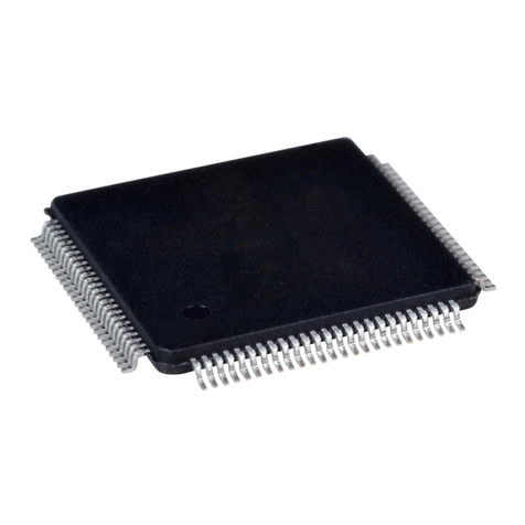
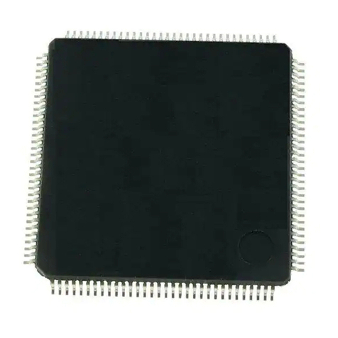
Epson S1R72104 User manual

Technical Manual
SCSI Interface Controller
S1R72104
MF1529-01

NOTICE
No part of this material may be reproduced or duplicated in any form or by any means without the written
permission of Seiko Epson. Seiko Epson reserves the right to make changes to this material without notice.
Seiko Epson does not assume any liability of any kind arising out of any inaccuracies contained in this material
or due to its application or use in any product or circuit and, further, there is no representation that this material
is applicable to products requiring high level reliability, such as, medical products. Moreover, no license to
any intellectual property rights is granted by implication or otherwise, and there is no representation or warranty
that anything made in accordance with this material will be free from any patent or copyright infringement of a
third party. This material or portions thereof may contain technology or the subject relating to strategic
products under the control of the Foreign Exchange and Foreign Trade Law of Japan and may require an export
license from the Ministry of International Trade and Industry or other approval from anther government agency.
©SEIKO EPSON CORPORATION 2002, All rights reserved.
All other product names mentioned herein are trademarks and/or registered trademarks of their respective
companies.

Configuration of product number
DEVICES
S1 R 72104 F 00B0 00
Packing specifications
00: Besides tape & reel
0A: TCP BL 2 directions
0B: Tape & reel Back
0C: TCP BR 2 directions
0D: TCP BT 2 directions
0E: TCP BD 2 directions
0F: Tape & reel FRONT
0G:TCP BT 4 directions
0H: TCP BD 4 directions
0J: TCP SL 2 directions
0K: TCP SR 2 directions
0L: Tape & reel LEFT
0M:TCP ST 2 directions
0N: TCP SD 2 directions
0P: TCP ST 4 directions
0Q:TCP SD 4 directions
0R: Tape & reel RIGHT
99: Specs not fixed
Specifications
Shape
(F : QFP)
Model number
Model name
(R : Exclusive use controller, Peripheral)
Product classification
(S1:Semiconductors)

Rev.1.1 EPSON i
CONTENTS
1. DESCRIPTION....................................................................................................................................1
2. FEATURES.........................................................................................................................................1
3. BLOCK DIAGRAM.............................................................................................................................2
4. PIN ASSIGNMENT.............................................................................................................................3
5. PIN DESCRIPTION.............................................................................................................................4
6. FUNCTIONAL DESCRIPTION...........................................................................................................6
6.1 CPU Interface Circuit..................................................................................................................6
6.2 Internal Registers........................................................................................................................6
6.3 Port Interface Circuit...................................................................................................................6
6.4 DMA Control Circuit....................................................................................................................6
6.5 SCSI-2 Interface Circuit..............................................................................................................6
6.6 PLL Circuit (Internal System Clock Generating Section)...........................................................7
7. FUNCTION OF REGISTERS..............................................................................................................8
7.1 List of Registers..........................................................................................................................8
7.2 List of Registers/Bits...................................................................................................................9
7.3 Detailed Description of Each Register......................................................................................10
7.3.1 Main Interrupt Status (MAININT) R/W.......................................................................10
7.3.2 SCSI Interrupt Status 1 (SCSIINT1) R/W..................................................................11
7.3.3 SCSI Interrupt Status 2 (SCSIINT2) R/W..................................................................12
7.3.4 Reset (RESET) W......................................................................................................12
7.3.5 SCSI Mode Select0 (SCSIMODE0) R/W ..................................................................13
7.3.6 SCSI Mode Select1 (SCSIMODE1) R/W ..................................................................14
7.3.7 SCSI Control (SCSICTL) R/W...................................................................................14
7.3.8 SCSI Data (SCSIDATA) R/W.....................................................................................15
7.3.9 Synchronize Transfer Mode (SYNCMODE) R/W......................................................15
7.3.10 SCSI Own ID (OWNID) R/W ...................................................................................16
7.3.11 Source/Destination ID (SDID) R/W..........................................................................16
7.3.12 Selection Timeout Counter (SLTIME) R/W..............................................................16
7.3.13 FIFO Control (FIFOCTL) R/W .................................................................................16
7.3.14 FIFO Data (FIFODATA) R/W...................................................................................17
7.3.15 Non DMA Transfer Size (NDMASIZ) R/W...............................................................17
7.3.16 SCSI Command (COMMAND) R/W........................................................................17
7.3.17 DMA Control (DMACTL) R/W..................................................................................17
7.3.18 DMA Transfer Byte Count 2 (DTBC2) R/W.............................................................17
7.3.19 DMA Transfer Byte Count 1 (DTBC1) R/W.............................................................17
7.3.20 DMA Transfer Byte Count 0 (DTBC0) R/W.............................................................18
7.3.21 CONFIG0 (CONFIG0) R/W.....................................................................................18
7.3.22 CONFIG1 (CONFIG1) R/W.....................................................................................19
7.3.23 Test (TEST) R(/W)...................................................................................................20
7.3.24 Revision Reg. (REVISION) R..................................................................................20
7.4 SCSI Control Commands.........................................................................................................20
7.4.1 Control Commands and Command Codes..................................................................20
7.4.2 Description of Each Control Command........................................................................21
7.4.3 Command Execution and State Transition ..................................................................28
ii EPSON Rev.1.1
7.5 Others and Cautions about Operation .....................................................................................29
8. ELECTRICAL CHARACTERISTICS................................................................................................30
8.1 Absolute Maximum Ratings......................................................................................................30
8.2 Recommended operational conditions.....................................................................................30
8.3 DC Characteristics....................................................................................................................30
8.4 AC Characteristics....................................................................................................................33
8.4.1 CPU Interface...............................................................................................................34
8.4.2 SCSI Interface..............................................................................................................36
8.4.3 Port Interface................................................................................................................49
8.4.4 Others...........................................................................................................................53
9. EXAMPLES OF CONNECTION.......................................................................................................56
10. EXTERNAL DIMENSIONS DRAWING..........................................................................................57

S1R72104 Technical Manual
Rev.1.1 EPSON 1
1. DESCRIPTION
S1R72104 is a SCSI interface control IC compatible with SCAM and FAST20 transfer.
2. FEATURES
«CPU Interface»
Connectable to a general-purpose CPU
«SCSI Interface»
Compatible with SCSI-2 (10Mbps (synchronous), 5Mbps (asynchronous))
Compatible with SCSI-3 FAST20 (20Mbps (synchronous))
Compatible with SCAM Lv.1 (compatible with Lv.2 with firmware)
Automatic processing of phase control
Built-in single end driver
Active negation I/O mounted
«PORT Interface»
Connectable directly to an IDE (ATA) DMA port.
Operational also as a general-purpose port.
«Others»
Built-in oscillation circuit: 20MHz/22.5MHz/40MHz
Built-in PLL circuit
100 pin QFP (0.5 mm pitch)
Supply voltage: 5.0V±10% and 3.3V±0.3V
No anti-radiation design

S1R72104 Technical Manual
2 EPSON Rev.1.1
3. BLOCK DIAGRAM
Port interface section
Master mode control
Slave mode control
Bus control
Clock control
section
SCSI-2(3) interface section
XPDREQ
XPDACK
CLKO
2 Multiplying PLL
PD15-0
XPRD
XPWR
Sequence
control
Command
analysis and
execution
Phase
control
Parity
GEN/CHK
FIFO
(16Byte)
DMA control
FIFO control
Asynchro-
nous transfer
control
Synchronous
transfer
SCAM
control
XSRST
XSATN
XSDP
XSBSY
XSIO
XSCD
XSMSG
XSSEL
XSDB7-0
XSREQ
XSACK
Clock distribution
CPU interface
section
Timing control
Interrupt control
Data MPX
DMA control
section
Start-up/stop control
Internal
register
CLKI
XPLLPW
VC
AD4-0
DB7-0
XCS
XRD
XWR
XINT
XRESET
TEST

S1R72104 Technical Manual
Rev.1.1 EPSON 3
4. PIN ASSIGNMENT
S1R72104F00B (QFP15-100pin)
VSS
NC
XSBSY
HVDD
XSACK
VSS
XSRST
XSMSG
VSS
XSSEL
XSCD
VSS
XSREQ
HVDD
XSIO
VSS
PD7
PD8
PD6
PD9
PD5
PD10
PD4
PD11
LVDD
75
74
73
72
71
70
69
68
67
66
65
64
63
62
61
60
59
58
57
56
55
54
53
52
51
HVDD 76 50 VSS
XSATN 77 49 PD3
VSS 78 48 PD12
XSDBP 79 47 PD2
HVDD 80 46 PD13
XSDB7 81 45 HVDD
VSS 82 44 PD1
NC 83 43 PD14
XSDB6 84 42 PD0
HVDD 85 41 PD15
XSDB5 86 40 PDREQ
VSS 87 39 XPWR
XSDB4 88 38 XPRD
HVDD 89 37 XPDACK
XSDB3 90 36 VSS
VSS 91 35 XCS
XSDB2 92 34 XINT
NC 93 33 XRESET
HVDD 94 32 XRD
XSDB1 95 31 XWR
VSS 96 30 AD4
XSDB0 97 29 AD3
HVDD 98 28 AD2
NC 99 27 AD1
VSS 100 26 LVDD
1
2
3
4
5
6
7
8
9
10
11
12
13
14
15
16
17
18
19
20
21
22
23
24
25
LVDD
EXCLK
VSS
OSCIN
OSCOUT
LVDD
CLKSEL0
CLKSEL1
VC
XPLLPD
PLLCT0
PLLCT1
TESTMON
TESTEN
DB0
DB1
DB2
DB3
HVDD
DB4
DB5
DB6
DB7
AD0
VSS
INDEX
EPSO
TOP View
INDEX
S1R72104
EPSO
TOP View
INDEX
EPSO
TOP View
INDEX
EPSON

S1R72104 Technical Manual
4 EPSON Rev.1.1
5. PIN DESCRIPTION
The control signal with “X” at the head of a pin name is LOW-active.
Pin No. Symbol I/O Functional description Remarks
SCSI interface-related matters (18)
97 XSDB0 Is/Otr SCSI data signal (SD0 to SD7) Drive capability 48mA
95 XSDB1
92 XSDB2
90 XSDB3
88 XSDB4
86 XSDB5
84 XSDB6
81 XSDB7
79 XSDBP SCSI data parity signal Drive capability 48mA
77 XSATN I/Ood SCSI ATN signal Drive capability 48mA
73 XSBSY I/Ood SCSI BSY signal Drive capability 48mA
71 XSACK Is/Otr SCSI ACK signal Drive capability 48mA
69 XSRST I/Ood SCSI RST signal Drive capability 48mA
68 XSMSG I/Ood SCSI MSG signal Drive capability 48mA
66 XSSEL I/Ood SCSI SEL signal Drive capability 48mA
65 XSCD I/Ood SCSI C/D signal Drive capability 48mA
63 XSREQ Is/Otr SCSI REQ signal Drive capability 48mA
61 XSIO I/Ood SCSI I/O signal Drive capability 48mA
Port interface-related matters (20)
38 XPRD Is/O Port lead signal Drive capability 3mA
39 XPWR Is/O Port right signal Drive capability 3mA
40 PDREQ Is/O Port DMA request signal (also operable in negative logic) Drive capability 6mA
37 XPDACK Is/O Port DMA ACK signal Drive capability 3mA
42 PD0 I/O Port DMA data bus signal (PD0 to 15) Drive capability 3mA
44 PD1
47 PD2
49 PD3
53 PD4
55 PD5
57 PD6
59 PD7
58 PD8
56 PD9
54 PD10
52 PD11
48 PD12
46 PD13
43 PD14
41 PD15

S1R72104 Technical Manual
Rev.1.1 EPSON 5
Pin No. Symbol I/O Functional description Remarks
CPU interface-related matters (17)
24 AD0 Ipu Address input pin (AD0 to AD4)
27 AD1
28 AD2
29 AD3
30 AD4
15 DB0 Ipu/O Data pin (DB0 to DB7) Drive capability 3mA
16 DB1
17 DB2
18 DB3
20 DB4
21 DB5
22 DB6
23 DB7
35 XCS Ispu Chip select signal for accessing internal register
34 XINT Otr Interrupt request output signal Drive capability 6mA
32 XRD Ispu Data lead signal
31 XWR Ispu Data write signal
Others (17)
4 OSCIN I Input to built-in oscillation circuit (40MHz, 20MHz or
22.5MHz)
5 OSCOUT O Output from built-in oscillation circuit
13 TESTMON O Monitor output for testing (open “LOW” output usually) Drive capability 2mA
33 XRESET Ipu System reset input signal
14 TESTEN Ipd Pin for testing (connected to LOW (GND) usually)
7 CLKSEL0 I Input clock selection: LOW(GND): OSCIN / HIGH(LVDD):
EXCLK input
8 CLKSEL1 I System clock selection: LOW(GND): PLL output /
HIGH(LVDD): Selecting signal of CLKSEL0
11 PLLCT0 I Dependent on PLL operation control pin input clock; input
on 3.3V level
12 PLLCT1 I Dependent on PLL operation control pin input clock; input
on 3.3V level
2 EXCLK I 5V level external clock input pin (connected to LOW (GND)
when not used)
10 XPLLPD I PLL power-down pin
LOW (GND): PLL Power-down mode / HIGH (LVDD): PLL
operation
9 VCO Internal VCO control pin
74,83,
93,99 NC
-
Not connected to IC chips (open usually)
HVDD:5V (5)
19,45,62,
72,76,80,
85,89,94,
98
HVDD P Power supply for 5V interface
LVDD:3.3V (6)
1,6,26,51
LVDD P Power supply for internal operation
VSS:0V (17)
3,25,36,
50,60,64,
67,70,75,
78,82,87,
91,96,100
VSS P GND
Note : I : Input O : Output
Is : Schmitt input Ood : Open drain output
Ipu : Pull-up input Otr : Tristate output
Ispu : Pull-up Schmitt input Ipd : Pull-down input

S1R72104 Technical Manual
6 EPSON Rev.1.1
6. FUNCTIONAL DESCRIPTION
6.1 CPU Interface Circuit
This block can be interfaced to a general-purpose CPU. It controls the interface with the CPU generally.
If XCS signal from CPU is LOW, the block can access the internal register. It decodes the address bus AD4 to
AD0 to generate the address of the internal register. At this time, it generates the read/write strobe signal from
XRD/XWR signal, transferring data between the internal register. A wait signal to CPU is not generated
because of no-wait operation.
6.2 Internal Registers
Refer to the section of Register Functions as for the addresses of the internal registers and description of each
bit. The main functions of this block are as follows:
(1) It generates control signals to each block according to the address, write-data and write-strobe signals
generated by the CPU interface circuit.
(2) It stores the status signals from each block, and outputs data according to the address and read-strobe
signals sent from the CPU interface circuit.
6.3 Port Interface Circuit
This is a block controlling the transfer to and from the external DMA port. It has the following functions:
(1) It controls the linkage operation of each functional block according to the control signal and the
stop-operation signal sent from the DMA control circuit.
(2) It control the transfer status of the external port according to PDREQ/XPDACK signals.
(3) It reads/writes the data of the data bus PD15-0 of the port from/to FIFO in SCSI-2 block. If the transfer
becomes impossible because of FIFO’s full/empty state, the block suspends transfer to and from the port
according to the timing specified by the PDREQ/XPDACK signals.
(4) The port allows selection of bit width 8 or 16.
(5) The port interface allows selection of the master or slave function (toward PDREQ/XPDACK/XPRD/XPWR
direction).
6.4 DMA Control Circuit
This is a block which controls the transfer between DMA port and FIFO in SCSI-2 block. It has the following
functions:
(1) It controls the linkage operation of each functional block according to the control signal from the internal
register and the information and stop-operation signals from each block.
(2) It stores the status of each of functional blocks when their linkage operation ends, reporting it to the
internal register at the specified timing.
6.5 SCSI-2 Interface Circuit
This is a block which controls the interfaces conforming to the SCSI-2 standard in general. It has the
following functions:
(1) It performs the SCSI protocol control automatically with hardware.
(2) It has 16-staged off-set counter to control the off-set and transfer rate during synchronous transfer.
(3) In the command phase, it distinguishes automatically the groups of commands received (in Target mode).
(4) It controls the automatic status/message transfer function. It supports the messages 00h/0Ah/0Bh (in
Target mode).
SCAM compatibility
Besides the traditional SCSI, this LSI has some additional functions compatible to SCAM (SCSI Configured
Auto Magnify) as listed below. .
These functions allow a device to operate as a SCAM Lv.1 drive.
(1) It monitors and recognizes SCAM selection and generates interruption.
(2) It responds to the selection response delay of 4ms or more, so it can distinguish SCAM selection from
ordinary selection.
(3) It can operate SCSI bus’s signal line directly because of its actual operation responding to SCAM selection
and sending/receiving data.

S1R72104 Technical Manual
Rev.1.1 EPSON 7
6.6 PLL Circuit (Internal System Clock Generating Section)
This IC has the function to generate 40MHz required for the internal circuit from the clock generated by the
oscillation circuit or inputted from EXCK pin by using PLL circuit.
The block diagram around the oscillation section is shown below: Internal clock
• The IC allows to structure a oscillation circuit easily by connecting crystal vibrator, ceramic vibrator and
feedback resistance.
(As for the characteristics of the ceramic vibrator, please consult with us separately.)
• It allows oscillation of 20MHz/22.5MHz/40MHz by means of the oscillation circuit mentioned above.
• It allows inputting external clock of 5V level and 2.5MHz/20MHz/22.5MHz/40MHz from the EXCLK pin.
• It allows inputting external clock of 3.3V level and 2.5MHz/20MHz/22.5MHz/40MHz from the OSCIN
pin.
• No PLL circuit is used because the internal clock can get necessary clock if the oscillator section is
oscillated at 40MHz, or if 40MHz clock is input from EXCLK pin.
• If EXCLK pin is used, set OSCIN pin to “LOW”; if OSCIN pin is used, set EXCLK pin to “LOW”.
Make settings as shown below depending on the ways of use (1:LVDD , 0:VSS):
If oscillator circuit is used If external clock of 3.3V level is
input from OSCIN pin If external clock of 5V level is
input from EXCLK pin
Oscillation/
input clock 20MHz 22.5MHz 40MHz 2.5MHz 20MHz 22.5MHz 40MHz 2.5MHz 20MHz 22.5MHz 40MHz
CLKSEL0 0 0 0 0 0 0 0 1 1 1 1
XPLLPD 1 1 0 1 1 1 0 1 1 1 0
PLLCNT0 0 1 0 0 0 1 0 0 0 1 0
PLLCNT1 0 1 0 1 0 1 0 1 0 1 0
CLKSEL1 0 0 1 0 0 0 1 0 0 0 1
• PLLcircuitspecifications Ta=0to70°C LVDD=3.3V±0.3V
Item Specifications
Lock-up time Within 1ms after oscillation was stabilized
Jitter Within ±2ns
A
B Y
S
PLL
Internal clock
CLKSEL1
XPLLPD
PLLCNT0
PLLCNT1
V
C
6.8k
Ω
100pF
GND
CLKSEL0
OSCOUT
5pF
GND
A
B Y
S
5pF
GND
OSCIN
1M
Ω
EXCLK

S1R72104 Technical Manual
8 EPSON Rev.1.1
7. FUNCTION OF REGISTERS
7.1 List of Registers
Address Register name Abridged name
00h Main Interrupt Status MAININT
01h SCSI Interrupt Status 1 SCSIINT1
02h SCSI Interrupt Status 2 SCSIINT2
03h - Reserved -
-
04h - Reserved -
-
05h - Reserved -
-
06h - Reserved -
-
07h RESET RESET
08h - Reserved -
-
09h SCSI Mode0 SCSIMODE0
0Ah SCSI Mode1 SCSIMODE1
0Bh SCSI Control SCSICTL
0Ch SCSI DATA SCSIDATA
0Dh SCSI Synchronous data transfer Mode SYNCMODE
0Eh SCSI Own ID OWNID
0Fh SCSI Source/Destination ID SDID
10h SCSI Selection Timeout Counter SELTIME
11h SCSI FIFO Control FIFOCTL
12h SCSI FIFO Data FIFODATA
13h SCSI Non-DMA Transfer Size NDMASIZE
14h SCSI Command COMMAND
15h - Reserved -
-
16h - Reserved -
-
17h DMA Control DMACTL
18h - Reserved -
-
19h Host Transfer Byte Count2 HTBC2
1Ah Host Transfer Byte Count1 HTBC1
1Bh Host Transfer Byte Count0 HTBC0
1Ch Config0 CONFIG0
1Dh Config1 CONFIG1
1Eh Test TEST
1Fh Revision REVISION

S1R72104 Technical Manual
Rev.1.1 EPSON 9
7.2 List of Registers/Bits
Address Type Register Name Default value Bit7 Bit6 Bit5 Bit4 Bit3 Bit2 Bit1 Bit0
00h R/W MAININT 00h GOOD SABT EXEC SCSI1 SCSI2
-
DTCMP ASCMP
01h R/W SCSIINT1 00h SPERR IDERR SELTO SATN BFREE ILPHS SCSEL WOATN
02h R/W SCSIINT2 00h
-
SRST OFERR UNDEF CMDER RESEL SEL LARBT
03h
- -
-
-
-
-
-
-
-
-
-
04h
-
-
-
-
-
-
-
-
-
-
-
05h
-
-
-
-
-
-
-
-
-
-
-
06h
-
-
-
-
-
-
-
-
-
-
-
07h W RESET
-
-
-
-
-
-
-
-
-
08h
-
-
-
-
-
-
-
-
-
-
-
09h R/W SCSIMODE0 80h SINTEN DTCD
-
ULTRAS AUTO1 AUTO2 AN_C AN_D
0Ah R/W SCSIMODE1 00h STPPE ATNPE STATN AUTO RINH SINH DACS SPCEN
0Bh R/W SCSICTL 00h ACK ATN SEL BSY REQ MSG I/O C/D
0Ch R/W SCSIDATA 00h DB7 DB6 DB5 DB4 DB3 DB2 DB1 DB0
0Dh R/W SYNCMODE 00h RATE3 RATE2 RATE1 RATE0 OFF3 OFF2 OFF1 OFF0
0Eh R/W OWNID 00h
-
-
-
-
-
OID2 OID1 OID0
0Fh R/W SDID xxh
-
SID2 SID1 SID0
-
DID2 DID1 DID0
10h R/W SELTIME 00h ST7 ST6 ST5 ST4 ST3 ST2 ST1 ST0
11h R/W FIFOCTL 01h
-
-
-
-
-
FCLR FULL EMPTY
12h R/W FIFODATA xxh FD7 FD6 FD5 FD4 FD3 FD2 FD1 FD0
13h R/W NDMASIZE FFh NSZ7 NSZ6 NSZ5 NSZ4 NSZ3 NSZ2 NSZ1 NSZ0
14h R/W COMMAND 00h CMD7 CMD6 CMD5 CMD4 CMD3 CMD2 CMD1 CMD0
15h
-
-
-
-
-
-
-
-
-
-
-
16h
-
-
-
-
-
-
-
-
-
-
-
17h R/W DMACTL 00h
-
-
-
-
-
-
FIFO DTGO
18h
-
-
-
-
-
-
-
-
-
-
-
19h R/W DTBC2 00h DBC23 DBC22 DBC21 DBC20 DBC19 DBC18 DBC17 DBC16
1Ah R/W DTBC1 00h DBC15 DBC14 DBC13 DBC12 DBC11 DBC10 DBC9 DBC8
1Bh R/W DTBC0 00h DBC7 DBC6 DBC5 DBC4 DBC3 DBC2 DBC1 DBC0
1Ch R/W CONFIG0 00h ACP INTLV PSLV
-
PRQLV SWAP ODS BUS8
1Dh R/W CONFIG1 00h NP3 NP2 NP1 NP0 AP3 AP2 AP1 AP0
1Eh R TEST 00h TM2 TM1 TM0 CKOUT
-
OFST SCBC DMBC
1Fh R REVISION 00h REV7 REV6 REV5 REV4 REV3 REV2 REV1 REV0

S1R72104 Technical Manual
10 EPSON Rev.1.1
7.3 Detailed Description of Each Register
7.3.1 Main Interrupt Status (MAININT) R/W
When the IC interrupted CPU, the CPU first reads this register for processing the interruption to get to know
which interrupt status register is the factor.
After reading this register, the CPU reads the interrupt status register corresponding to each bit to find out the
bit that is the source of interrupt, and processes the interruption appropriately. Then it writes the values read to
the interrupt status registers corresponding to each bit, then clearing the bits.
If GOOD, SABT, or DTCMP bit is the interrupt source, the CPU writes the value read to clear the bits. The
register has no need to clear directly any other bits.
7 6 5 4 3 2 1 0
GOOD SABT EXEC SCSI1 SCSI2
-
DTCMP ASCMP 00h
AUTO SEQUENCE COMPLETE
DMA TRANSFER COMPLETE
SCSI INTERRUPT STATUS 2
SCSI INTERRUPT STATUS 1
EXECUTING SCSI COMMAND
ABORTED SCSI COMMAND
SCSI COMMAND NORMAL COMPLETE
BIT7 SCSI COMMAND NORMAL COMPLETE
This bit becomes HIGH if a SCSI control command closed normally.
BIT6 ABORTED SCSI COMMAND
This bit becomes HIGH if a control command was forced to terminate by Abort command issued.
BIT5 EXECUTING SCSI COMMAND
This bit is HIGH while a SCSI control command is under execution. This bit is not a factor causing interrupt to the
CPU, so HIGH of this bit causes no interruption. It is used to monitor the execution of SCSI control command.
BIT4 SCSI INTERRUPT STATUS 1
This bit becomes HIGH if any interrupt factor about the SCSI interface is shown on SCSIINT1 register.
BIT3 SCSI INTERRUPT STATUS 2
This bit becomes HIGH if any interrupt factor about the SCSI interface is shown on SCSIINT2 register.
BIT1 DMA TRANSFER COMPLETE
This bit becomes HIGH when DMA data transfer activated by DMACTL register ends.
It becomes HIGH also when the transfer is forced to terminate by “0” written in DTGO bit of DMACTL register.
It becomes HIGH also if a command is aborted by Abort_SCSI command or if a command under execution is aborted
by ATN assertion after DTGO bit of DMACTL register was set because DMA terminates.
BIT0 AUTO SEQUENCE COMPLETE
This bit becomes HIGH when AUTO1 or AUTO2 bit of SCSIMODE0(09h) is set and the command processing
specified is over.

S1R72104 Technical Manual
Rev.1.1 EPSON 11
7.3.2 SCSI Interrupt Status 1 (SCSIINT1) R/W
Shows the result of a SCSI control command executed.
The CPU can recognize the interrupt source by reading this register after receiving the interrupt signal. It
clears the bit by writing again the value read.
7 6 5 4 3 2 1 0
SPERR IDERR SELTO SATN BFREE ILPHS
SCSEL WOATN 01h
SELECTED WITHOUT ATTENTION
SCAMSELECTED
ILLEGAL PHASE CHANGE DETECTED
BUS FREE DETECTED
SCSI ATN ASSERTION DETECTED
SELECTIONTIMEOUT
ID ERROR DETECTED
SCSI DATA PARITY ERROR DETECTED
BIT7 SCSI DATA PARITY ERROR DETECTED
This bit becomes HIGH if a parity error was detected on SCSI data bus.
BIT6 ID ERROR DETECTED
This bit becomes HIGH if an error was detected about ID bit during the selection or reselection phase. The error
about ID bit shows that:
Only one ID bit is asserted. or,
Three or more ID bits are asserted.
BIT5 SELECTION TIME OUT
This bit becomes HIGH if time-out was detected during the selection or reselection phase.
BIT4 SCSI ATN ASSERTION DETECTED
This bit becomes HIGH if SCSI ATN was asserted. It is not set, though, in the sequence where SCSI ATN is asserted
usually, such as the message-out phase subsequent to selection.
BIT3 BUS FREE DETECTED
This bit becomes HIGH if SCSI control command detected the busfree phase during its execution.
BIT2 ILLEGAL PHASE CHANGE DETECTED
This bit becomes HIGH if a SCSI control command detected unexpected phase transition during its execution.
It is valid only in Initiator mode.
BIT1 SCAM SELECTED
This bit becomes HIGH if SCAM selection was responded to.
BIT0 SELECTED WITHOUT ATTENTION
This bit becomes HIGH if the selection which does not assert ATTENTION was responded to.
Even if this bit is set, a SCSI control command continues execution. If a command block remains received, though,
the first byte of SCSI-FIFO has the command code.

S1R72104 Technical Manual
12 EPSON Rev.1.1
7.3.3 SCSI Interrupt Status 2 (SCSIINT2) R/W
Shows the result of a SCSI control command executed.
The CPU can recognize the interrupt source by reading this register after receiving the interrupt signal. It
clears the bit by writing again the value read.
7 6 5 4 3 2 1 0
-
SRST OFERR UNDEF CMDER RESEL SEL LARBT 02h
LOST ARBITRATION
SELECTED
RESELECTED
COMMAND ERROR
UNDEFIND GROUP COMMAND
OFFSET ERRORINSYNCHRONOUS TRANSFER
SCSI RST ASSERTION DETECTED
BIT7 RESERVED
BIT6 SCSI RST ASSERTION DETECTED
This bit becomes HIGH if SCSI RST was asserted.
BIT5 OFFSET ERROR IN SYNCHRONOUS TRANSFER
This bit becomes HIGH if an off-set error occurred during synchronous transfer. The off-set error means that the
off-set counter is not reset to “0” when transfer ends, or that the counter overflows/underflows.
BIT4 UNDEFIND GROUP COMMAND
This bit becomes HIGH if SCSI command other than group 0, 1, 2, or 5 was received.
BIT3 COMMAND ERROR
This bit becomes HIGH if an undefined SCSI control command was issued or a control command was issued during
execution of another command.
BIT2 RESELECTED
This bit becomes HIGH if any other device made re-selection during execution of a command other than the SCSI
control command which makes re-selection.
BIT1 SELECTED
This bit becomes HIGH if any other device made selection during execution of a command other than SCSI control
command which makes selection.
BIT0 LOST ARBITRATION
This bit becomes HIGH in the case of defeat in the arbitration phase. If this bit is HIGH and no other device made
selection or re-selection , the IC suspends the operation of the control commands.
7.3.4 Reset (RESET) W
Writing in this register initializes the inside of the circuit. Any value may be entered.
7 6 5 4 3 2 1 0
07h
MSB LSB

S1R72104 Technical Manual
Rev.1.1 EPSON 13
7.3.5 SCSI Mode Select0 (SCSIMODE0) R/W
Makes the operational settings related to SCSI interface.
7 6 5 4 3 2 1 0
SINTEN DTCD
-
ULTRAS AUTO1 AUTO2
AN_C AN_D 09h
ACTIVE NEGATION DATA
ACTIVE NEGATION CONTROL
AUTO2 (status message stop)
AUTO1 (auto status)
ULTRA SCSI
DTCMP DISABLE
SCSI INTERRUPT ENABLE
BIT7 SCSI INTERRUPT ENABLE
If this bit is HIGH, any SCSI interruption but DTCMP is enabled.
[ASCMP may occur if this bit is HIGH. If the IC is used in polling processing, make firmware ignore the ASCMP
interruption.]
BIT6 DTCMP DISABLE
If this bit is HIGH, DTCMP interrupt is disabled.
BIT5 RESERVED
BIT4 ULTRA SCSI
If this bit is HIGH, ULTRA-SCSI transfer is enabled. It is valid only when RATE bit of SYNCMODE register is set
to “0” or “1”.
BIT3 AUTO1 (auto status)
Executes automatically STS_MSG, Busfree, and Wait_SEL_CMD after DMA_DATA_IN/OUT command was
executed.
At the end of execution, ASCMP interrupt occurs. The bit is valid also in FIFO-DMA mode.*AUTO
BIT2 AUTO2 (status message stop)
Executes automatically STS_MSG after DMA_DATA_IN/OUT command was executed.
At the end of execution, ASCMP interrupt occurs. The bit setting is valid also in FIFO-DMA mode.
[When this bit is used, EXECbit is not turned OFF even if ASCMP occurs. Configure the firmware so that it ignores
the status of EXECbit.] *AUTO
*AUTO :
During the execution of AUTO1 or 2, AUTO bit of SCSIMODE1 register is deemed as “1”.
Also, EXEC bit is “1” during the execution of AUTO1 or 2. Because internal sequencer writes the command in
SCSI block for CPU, COMMAND register can read the command value then under execution.
DTCMP interrupt occurs irrespective of the settings of AUTO1or 2. Set DTCD (bit6) of this register to “Hi” to
disable such interruption.
BIT1 ACTIVE NEGATION CONTROL
HIGH of this bit enables the function of active negation of SCSI REQ/ACK signals.
BIT0 ACTIVE NEGATION DATA
HIGH of this bit enables the function of active negation of the SCSI data and parity signals.

S1R72104 Technical Manual
14 EPSON Rev.1.1
7.3.6 SCSI Mode Select1 (SCSIMODE1) R/W
Makes the operational settings related to SCSI interface.
7 6 5 4 3 2 1 0
STPPE ATNPE STATN AUTO RINH SINH
DIRECT SPCEN 0Ah
SCSI PARITY CHECK ENABLE
SCSI DIRECT ACCESS ENABLE
SELECTION INHIBIT
RESELECTION INHIBIT
AUTO SEND STATUS/MESSAGE
STOP BY ATN ASSERT
ATN ASSERT BY PARITY ERROR
STOP BY PARITY ERROR
BIT7 STOP BY PARITY ERROR
HIGH of this bit suspends a SCSI control command under execution if a parity error was detected on SCSI interface.
BIT6 ATN ASSERT BY PARITY ERROR
HIGH of this bit makes ATN asserted against a target device if a parity error was detected on SCSI interface. Any
setting of this bit is invalid if SCSI parity check is disabled.
This bit is valid only in Initiator mode.
BIT5 STOP BY ATN ASSERT
HIGH of this bit suspends a SCSI control command under execution if ATN asserted was detected.
This bit is valid only in Target mode.
BIT4 AUTO SEND STATUS/MESSAGE
HIGH of this bit puts SCSI control command “Status_Message” into Automatic Transmission mode. In this mode,
FLAG and LINK bits of SCSI command block which have been received are checked; Status 00h(GOOD) and
message 00h(COMMAND COMPLETE), status 10h(INTERMEDIATE GOOD) and message 0Ah(LINKED
COMMAND COMPLETE), and status 10h(INTERMEDIATE GOOD) and message 0Bh(LINKED COMMAND
COMPLETE WITH FLAG) are sent automatically if LINK bit is LOW, LINK bit is HIGH and FLAG bit is LOW, and
LINK and FLAG bits are both HIGH, respectively.
BIT3 RESELECTION INHIBIT
HIGH of this bit disables response to re-selection.
BIT2 SELECTION INHIBIT
HIGH of this bit disables response to selection.
BIT1 SCSI DIRECT ACCESS ENABLE
HIGH of this bit allows direct control of SCSI signal lines from CPU by using SCSI data register and SCSI control
register. Also, it is possible always to monitor the status of the signal lines irrespective of the status of this bit.
BIT0 SCSI PARITY CHECK ENABLE
HIGH of this bit causes parity check of SCSI data bus during the selection phase (when itself is selected) and when
data is input through SCSI.
7.3.7 SCSI Control (SCSICTL) R/W
This register is accessed when CPU controls SCSI signal lines directly.
For such direct control, DIRECT (bit 1) must be set in the mode setting register (0Ah).
The status of each signal is stored as “active HIGH”.
7 6 5 4 3 2 1 0
ACK ATN SEL BSY REQ MSG
I/O C/D 0Bh
SCSIC/D
SCSII/O
SCSIMSG
SCSIREQ
SCSI BSY
SCSI SEL
SCSIATN
SCSI ACK

S1R72104 Technical Manual
Rev.1.1 EPSON 15
7.3.8 SCSI Data (SCSIDATA) R/W
The CPU accesses this register when it controls SCSI data bus directly. For such direct control, DIRECT (bit
1) must be set in the mode setting register (0Ah).
The status of each signal is stored as “active HIGH”. DIRECT setting does not decide whether parity bit is
output or not; it is output if it has been output before setting DIRECT, or it is not otherwise.
7 6 5 4 3 2 1 0
DB7
DB6 DB5 DB4 DB3 DB2 DB1 DB0 0Ch
MSB LSB
7.3.9 Synchronize Transfer Mode (SYNCMODE) R/W
Sets transfer rate and off-set for SCSI synchronous transfer.
7 6 5 4 3 2 1 0
RATE3 RATE2 RATE1 RATE0 OFF3 OFF2
OFF1 OFF0 0Dh
SYNCHRONOUS OFFSET
SYNCHRONOUS TRANSFER RATE
RATE3-0 ASSERT NEGATE PERIOD OFF3-0 OFFSET
0000 1T 1T 2T 0000 Asynchronous
0001 2T 1T 3T
Note 1 0001 1
0010 2T 2T 4T 0010 2
0011 3T 2T 5T 0011 3
0100 3T 3T 6T 0100 4
0101 4T 3T 7T 0101 5
0110 4T 4T 8T 0110 6
0111 5T 4T 9T 0111 7
1000 5T 5T 10T 1000 8
1001 6T 5T 11T 1001 9
1010 6T 6T 12T 1010 10
1011 7T 6T 13T 1011 11
1100 7T 7T 14T 1100 12
1101 8T 7T 15T 1101 13
1110 8T 8T 16T 1110 14
1111 9T 8T 17T 1111 15
Note) T has double the cycle of internal clock (40MHz).
Note 1) If ULTRA bit of SCSIMODE0 register is set, T has the same cycle as internal clock (40MHz) only if the value set for
RATE3 to 0 bit is 1 or less.
Table of contents
Other Epson Controllers manuals

Epson
Epson TP3 User manual

Epson
Epson S1R72105 User manual

Epson
Epson RC180 User manual

Epson
Epson SRC520 User manual

Epson
Epson S1R72U16 Installation instructions

Epson
Epson RC90 User manual

Epson
Epson S1D13506 User manual

Epson
Epson S1D13504 User manual

Epson
Epson S1D13503 Series User manual

Epson
Epson RC700 User manual
Popular Controllers manuals by other brands

NXP Semiconductors
NXP Semiconductors 56800E Reference manual

Lumel
Lumel re72 series User Manual & Quick Start

Cisco
Cisco Catalyst 9800-L Installing Instruction

Leviton
Leviton DRKDN-U Series installation instructions

Cardax
Cardax FT Controller 3000 Installation note

Siemens
Siemens SIMOTION operating instructions