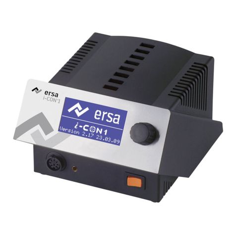
ersa i-CON 1V User manual

Ersa GmbH
Leonhard-Karl-Str. 24 Phone: +49 9342/800-0
97877 Wertheim/Germany Fax +49 9342/800-127
www.ersa.com [email protected]
Ersa i-CON 1V & i-CON 2V
Soldering station
Operating Instructions

60 3BA00231 · 2019-03-12 · Rev. 4 Ersa i-CON 1V & i-CON 2V
Table of Contents
Table of Contents
1. Introduction .......................................................................................................... 63
1.1 Supply unit............................................................................................................................ 63
2. Technical data ....................................................................................................... 64
3. Concerning your safety.......................................................................................... 67
3.1 Explanations on pictograms and symbols ........................................................................... 67
3.2 Safety instructions ............................................................................................................... 68
3.3 Intended use......................................................................................................................... 71
3.4 National and international regulations ............................................................................... 71
4. Transport, storage, waste disposal........................................................................ 72
5. Commissioning...................................................................................................... 73
5.1 Before start-up..................................................................................................................... 73
5.2 Switching on the first time....................................................................................................74
5.2.1 microSD card............................................................................................................. 75
5.2.1.1 Inserting a microSD card ...........................................................................76
6. Functional description........................................................................................... 77
6.1 Operation ............................................................................................................................. 77
6.2 The working mode ............................................................................................................... 77
6.2.1 Software version....................................................................................................... 78
6.2.2 Activating tools......................................................................................................... 78
6.2.3 Setting the heating level of the heating plate.......................................................... 78
6.2.4 Working with the heating plate................................................................................ 79
6.2.4.1 Heating plate power values........................................................................79
6.2.5 Working with three fixed temperatures (target temperatures).............................. 80
6.3 Parameter mode .................................................................................................................. 81
6.3.1 i-SET TOOL................................................................................................................. 81
6.3.2 Target temperature .................................................................................................. 82
6.3.2.1 Setting three target temperatures (fixed temperatures)..........................83
6.3.3 Calibration temperature........................................................................................... 83
6.3.4 Tip offset................................................................................................................... 84
6.3.5 Calibration ................................................................................................................ 85
6.3.6 Determining the calibration temperature ............................................................... 85

61
3BA00231 · 2019-03-12 · Rev. 4
Ersa i-CON 1V & i-CON 2V
Table of Contents
6.3.7 Energy ....................................................................................................................... 85
6.3.8 Standby period.......................................................................................................... 86
6.3.9 Standby temperature ............................................................................................... 87
6.3.10 Configuration mode.................................................................................................. 87
6.3.11 Temperature window ............................................................................................... 88
6.3.12 Process alarm............................................................................................................ 88
6.3.13 Password protection................................................................................................. 88
6.3.13.1 Setting the password..................................................................................89
6.3.13.2 Changing the password ..............................................................................90
6.3.13.3 Input without disabling the password .......................................................90
6.3.13.4 Forgotten password ...................................................................................91
6.3.14 Temperature unit...................................................................................................... 91
6.3.15 Language selection................................................................................................... 91
6.3.16 Adjustable shutdown function (idle state)............................................................... 91
6.3.17 Heating plate............................................................................................................. 92
6.3.17.1 Connecting heating plate to soldering station ..........................................92
6.3.17.2 Activating the heating plate.......................................................................92
6.3.18 Activating the soldering fume extraction ................................................................ 93
6.3.19 Fixed temperature.................................................................................................... 93
6.3.19.1 Enabling the fixed temperature function ..................................................93
6.4 Factory settings (“Default”)................................................................................................. 94
6.5 Contrast................................................................................................................................ 95
6.6 Changing soldering tips........................................................................................................ 96
6.6.1 Changing the i-TOOL soldering tip............................................................................ 96
6.6.1.1 Replacing the soldering tip in the soldering tip fastening.........................97
6.6.2 Changing the X-TOOL desoldering tip ...................................................................... 98
6.6.3 Changing the X-TOOL VARIO desoldering tip ........................................................... 98
6.6.4 Changing the CHIP TOOL VARIO soldering tip.......................................................... 99
6.7 Changing a heating element .............................................................................................. 100
6.7.1 Changing the i-TOOL heating element ................................................................... 100
6.7.2 Changing the CHIP TOOL heating element............................................................. 101
6.7.3 Changing the X-TOOL heating element .................................................................. 101
6.7.4 Changing the CHIP TOOL VARIO heating element ................................................. 101
6.7.5 Changing the X-TOOL VARIO heating head ............................................................ 102
6.8 Sensitive components........................................................................................................ 103
7. Error diagnosis and remedy................................................................................. 104
7.1 General errors .................................................................................................................... 104
7.2 Other faults ........................................................................................................................ 104

62 3BA00231 · 2019-03-12 · Rev. 4 Ersa i-CON 1V & i-CON 2V
7.3 Continuity test for i-Tool .................................................................................................... 105
7.3.1 Continuity test for i-TOOL heating element........................................................... 105
7.3.2 Continuity test for i-TOOL thermocouple .............................................................. 105
7.4 Continuity test for CHIP TOOL VARIO ................................................................................ 105
7.5 Continuity test for X-TOOL ................................................................................................. 106
7.5.1 Continuity test for X-TOOL heating element.......................................................... 106
7.5.2 Continuity test for X-TOOL thermocouple ............................................................. 107
7.6 Continuity test for X-TOOL VARIO heating element.......................................................... 107
7.7 Parameter changes not possible........................................................................................ 108
7.8 Error messages................................................................................................................... 109
8. Maintenance and cleaning .................................................................................. 110
8.1 Important care work .......................................................................................................... 110
8.2 Cleaning.............................................................................................................................. 110
9. Spare parts, accessories ...................................................................................... 111
9.1 QR code links and web addresses for tool tips in ERSA web shop.................................... 113
10. Warranty ............................................................................................................. 115
Table of Contents

63
3BA00231 · 2019-03-12 · Rev. 4
Ersa i-CON 1V & i-CON 2V
Introduction
1. Introducon
-
tory environments.
1.1 Supply unit
. This way you can
-
ments.

64 3BA00231 · 2019-03-12 · Rev. 4 Ersa i-CON 1V & i-CON 2V
Technical data
2. Technical data
Soldering staon i-CON 1V i-CON 2V
Designaon Value Value
Dimensions, mm 150 x 175 x 105
Weight, kg 3.0 3.7
Mains voltage, VAC 220-240
Mains frequency 50-60
Fuse (slow blowing), A 0.8
110-120
Mains frequency, Hz 50-60
Fuse (slow blowing), A 1,6
Secondary voltage, VAC 24
150
80 120
I
Permissible ambient temperature, °C 0-40
Temperature range (stepless), °C, °F 50-450, 122-842
< ± 2
< 2
< 2
4
Rear side interface
standby signal
-
Miscellaneous
Control technology -
TRONIC
LC-Display, blue
Conformity
Supply cable 2 m, PVC, with appliance socket
Acc. to MIL-SPEC/ESA-standard
VDE, EMC-tested
Connectable soldering and desoldering devices (depending on model): i-TOOL, CHIP TOOL, CHIP TOOL VARIO,
X-TOOL, X-TOOL VARIO, TECH TOOL, MICRO TOOL, POWER TOOL, i-SET TOOL

65
3BA00231 · 2019-03-12 · Rev. 4
Ersa i-CON 1V & i-CON 2V
Technical data
i-Tool soldering iron
Designaon Value
24
150
80
Approx. 10 s
Temperature range, °C 150 – 450 °C
Less than ± 2
Weight (without supply cable), Approx. 30 g
Miscellaneous
Desoldering iron CHIP TOOL
Designaon Value
24
Maximum heat output PTC 2 x 30 W/280 °C, 2 x 20 W/350 °C
Depending on desoldering
Temperature range, °C 150 – 450
Temperature sensor PTC
Weight (without supply cable), Approx. 75 g
Supply cable
Design
Desoldering CHIP TOOL VARIO
Designaon Value
24
80
Temperature range, °C 150 – 450
Temperature sensor
Weight (without supply cable), Approx. 30
Dimensions (without supply cable), mm Approx. 145 x 45 x 25
Supply cable, m Approx. 1,2
Design

66 3BA00231 · 2019-03-12 · Rev. 4 Ersa i-CON 1V & i-CON 2V
Technical data
Desoldering iron X-TOOL
Designaon Value
24
Heat-up power, 260 W
Temperature measurement K-type thermocouple
2, each 60 W (at 360 °C)
up to 800 mbar
Weight,
approx. 70 mm
Design
Desoldering iron X-TOOL VARIO
Designaon Value
24
Heat-up power, 150 W
approx. 35 s to 350 °C
Temperature range, °C 150 – 450
Temperature measurement Ni-CrNi thermocouple
Start vacuum, Up to 800 mbar
Weight,
Design

67
3BA00231 · 2019-03-12 · Rev. 4
Ersa i-CON 1V & i-CON 2V
Concerning your safety
3. Concerning your safety
Ersa products are developed, manufactured and tested in compliance with general
requirements concerning health and safety.
However, residual risk does remain!
3.1 Explanaons on pictograms and symbols
WARNING! Is used for warnings of immediate danger.
Not avoiding this danger may result in death, extremely serious injury or
property damage.
ATTENTION! Is used for warnings of possibly dangerous situaons.
Not avoiding this danger may result in death, extremely serious injury or
property damage.
ATTENTION Is used for warnings of possibly dangerous situaons.
Not avoiding this danger may result in minor injuries, light injuries or
property damage.
and hints.
■This symbol refers to

68 3BA00231 · 2019-03-12 · Rev. 4 Ersa i-CON 1V & i-CON 2V
Concerning your safety
3.2 Safety instrucons
WARNING! Malfuncons of the device possible!
Check all components before each use. Have damaged parts only
repaired by a specialist or the manufacturer. If repairs are carried out
use original Ersa spare parts for possible repairs.
ATTENTION Risk of burning!
-
connected with the thermal tool. The hot tool insert should never come
ATTENTION Risk of injury!
Keep unauthorized persons at a safe distance. Make sure that unautho-
rized persons, especially children, have no access to the thermal tools.
ATTENTION! Fire hazard!
-
ids and gases from the working range of the thermal tool. If work is inter-
rupted, always store the thermal tool in the workstand provided for this
ATTENTION! Fire hazard!
-
ATTENTION Risk of injury!
the risk of accidents.

69
3BA00231 · 2019-03-12 · Rev. 4
Ersa i-CON 1V & i-CON 2V
Concerning your safety
ATTENTION Eang and drinking prohibited!
Solders and solder auxiliaries are toxic. If they enter into the organism it
strictly prohibited.
solder auxiliaries.
CAUTION! Danger of poisoning by inhalaon!
-
CAUTION!Dangerous electrical voltage!
circuits or electric shocks and must therefore be immediately replaced.
ATTENTION! Fire hazard and dangerous electrical voltage!
CAUTION! Risk of injury!
Take care of your thermal tool. Always keep your Ersa product in a safe
and dry place, out of the reach of children. Follow the maintenance
accessories and spare parts from Ersa.
ATTENTION Risk of injury!
Physically and/or mentally disabled persons must only use the soldering
allowed to play with the soldering devices.

70 3BA00231 · 2019-03-12 · Rev. 4 Ersa i-CON 1V & i-CON 2V
Concerning your safety
This device can be used by children aged 8 and above as well as people
-
ence and knowledge provided they are supervised, have been instructed
Children are not allowed to play with the device. Cleaning and mainte-
nance must not be performed by children without supervision.
CAUTION! Wear protecve clothing!
CAUTION! Safe disposal of solder waste!
Solder waste is hazardous waste and must not be disposed with the nor-
mal household waste. Provide safe and environmentally friendly disposal
Note ESD sensive components!
the warnings on the packing or ask the manufacturer or supplier. To pro-
discharge).

71
3BA00231 · 2019-03-12 · Rev. 4
Ersa i-CON 1V & i-CON 2V
Concerning your safety
3.3 Intended use
case of unintended use and tampering with the device, any warranty and liability claims
of the buyer against the manufacturer will become null and void. Intended use also
3.4 Naonal and internaonal regulaons

72 3BA00231 · 2019-03-12 · Rev. 4 Ersa i-CON 1V & i-CON 2V
Transport, storage, waste disposal
4. Transport, storage, waste disposal
a dehumidifying agent. Damage caused by unprofessional transport or storage are not
covered under warranty.
Parliament and of the Council of 27 January 2003 on waste electrical and
electronic equipment:
Products marked with a crossed out waste bin must not be disposed of
-
-

73
3BA00231 · 2019-03-12 · Rev. 4
Ersa i-CON 1V & i-CON 2V
5. Commissioning
5.1 Before start-up
Please check the contents in the package for completeness. With regard to this, please
read the [Spare parts, accessories] chapter! Should any of the listed components be dam-
aged or incomplete, you should immediately consult your supplier.
i-CON 1V
Table of Contents
Order no.
0IC1100V 0IC1100V0C 0IC1100VCV 0IC1100VXV 0IC103A0C
i-CON 1V 0IC113V 1 x 1 x 1 x 1 x 1 x
i-TOOL 0100CDJ 1 x 1 x
CHIP TOOL VARIO 0460MDJ 1 x
X-TOOL VARIO 0740EDJ 1 x
Interface 1 x 1 x
All soldering irons come with a matching workstand.
i-CON 2V
Table of Contents
Order no.
0IC2200V 0IC2200VC 0IC2200VIT 0IC2200VXT 0IC2200V0C 0IC22300C
i-CON 2V 0IC223 1 x 1 x 1 x 1 x 1 x 1x
i-TOOL 0100CDJ 1 x 1 x 2 x 1 x 1 x
CHIP TOOL VARIO 0460MDJ 1 x
X-TOOL VARIO 0740EDJ 1 x
Vacuum station 0CU103A 1 x
Interface 1 x 1x
All soldering irons come with a matching workstand.
Commissioning

74 3BA00231 · 2019-03-12 · Rev. 4 Ersa i-CON 1V & i-CON 2V
5.2 Switching on the rst me
■
■Before switching on, make sure that the mains voltage complies with
■a.
i-CON 1V:
i-CON 2V:
The following combinaons are not possible:
le CHIP TOOL VARIO and right POWER TOOL as well as le CHIP TOOL VARIO and right CHIP TOOL VARIO.
OFF
_
i-TOOL, POWER TOOL, TECH-TOOL,
MICRO TOOL, X-TOOL, X-TOOL VARIO,
i-SET TOOL, CHIP TOOL, CHIP TOOL VARIO
Potentialausgleichsbuchse
i-TOOL, POWER TOOL, TECH-TOOL,
MICRO TOOL, X-TOOL, X-TOOL VARIO,
i-SET TOOL, CHIP TOOL, CHIP TOOL VARIO
Potenalausgleichsbuchse
i-TOOL, X-TOOL VARIO,
CHIP TOOL VARIO
Commissioning
Equipotential bonding socket

75
3BA00231 · 2019-03-12 · Rev. 4
Ersa i-CON 1V & i-CON 2V
■
■
socket. The pin in the plug must match the groove in
■
insert the plug into the socket and lock it. Store the
soldering tool in the workstand.
■Connect the mains supply cable with the soldering
➊ Interface (C models)
■
CAUTION! Risk of burning!
switched on!
5.2.1 microSD card
be found on the web pages of "www.kurtzersa.com". Log in to the free Members Area
0_
ON
Commissioning

76 3BA00231 · 2019-03-12 · Rev. 4 Ersa i-CON 1V & i-CON 2V
5.2.1.1 Inserng a microSD card
■Insert the microSD card into the port as
shown.
■
card is inserted correctly.
■If there is no tangible resistance take the card
out completely and try again.
■
as soon as the card is inserted correctly. For
■
i-CON 1V oder i-CON 2V under “Downloads”.
Commissioning

77
3BA00231 · 2019-03-12 · Rev. 4
Ersa i-CON 1V & i-CON 2V
6. Funconal descripon
6.1 Operaon
a at
switch will light up red.
The soldering station is controlled via a rotary encoder
to be pressed as a push-button. It is called i-OP. The i-OP
allows selecting desired functions or changing values.
A clockwise rotation will result in higher values and a
result in increments of one. Quick turning will change the selected values in increments
of 10/50/100 (depending on the corresponding parameter).
-
in plain text in a clearly structured display window.
6.2 The working mode
abof the solder-
■Actual value c.
■Target value and, where appropriate, standby status
④.
■Connected soldering tool (in our example i-Tool) e.
■f.
[Fixed temperature].
via the parameter mode. A password is needed to do so.
Functional description

78 3BA00231 · 2019-03-12 · Rev. 4 Ersa i-CON 1V & i-CON 2V
6.2.1 Soware version
keep it ready as our Service Department may ask you for it. -
queried in the [Contrast] menu. With regard to this, please read chapter 6.5 [Contrast].
6.2.2 Acvang tools
alternately by pressing the i-OP. A connected i-Tool, CHIP TOOL VARIO or X-TOOL VARIO is
via the parameter mode. A password is needed to do so.
6.2.3 Seng the heang level of the heang plate
-
■
row. The opposite display appears.
■
turning the i-OP.
■
Functional description
Other manuals for i-CON 1V
1
This manual suits for next models
1
Table of contents
Other ersa Soldering Gun manuals

ersa
ersa i-CON NANO MK2 User manual

ersa
ersa i-CON Nano User manual

ersa
ersa i-CON PICO User manual

ersa
ersa Solder Smart User manual

ersa
ersa i-CON NANO MK2 User manual

ersa
ersa RA 4500 D User manual

ersa
ersa i-CON 1V User manual

ersa
ersa DIGITAL 2000 A User manual

ersa
ersa ANALOG 60 User manual

ersa
ersa RDS 80 User manual
Popular Soldering Gun manuals by other brands

Surtek
Surtek 112554 User manual and warranty

Parkside
Parkside PLS 48 B1 Operation and safety notes

Hakko Electronics
Hakko Electronics FX-100-05 instruction manual

Fahrenheit
Fahrenheit 28523 user manual

Soldron
Soldron MSVW instruction manual

Weller
Weller WX Smart WXMPS MS Translation of the original instructions