ersa i-CON 1 User manual

Operatinginstructions
ERSA soldering station

i-CON 1 / 2
3BA00180 • 28.04.2008 • Rev. 1
Contents
1. Introduction .................................................................................................................... 4
1.1 Supply unit ............................................................................................................. 4
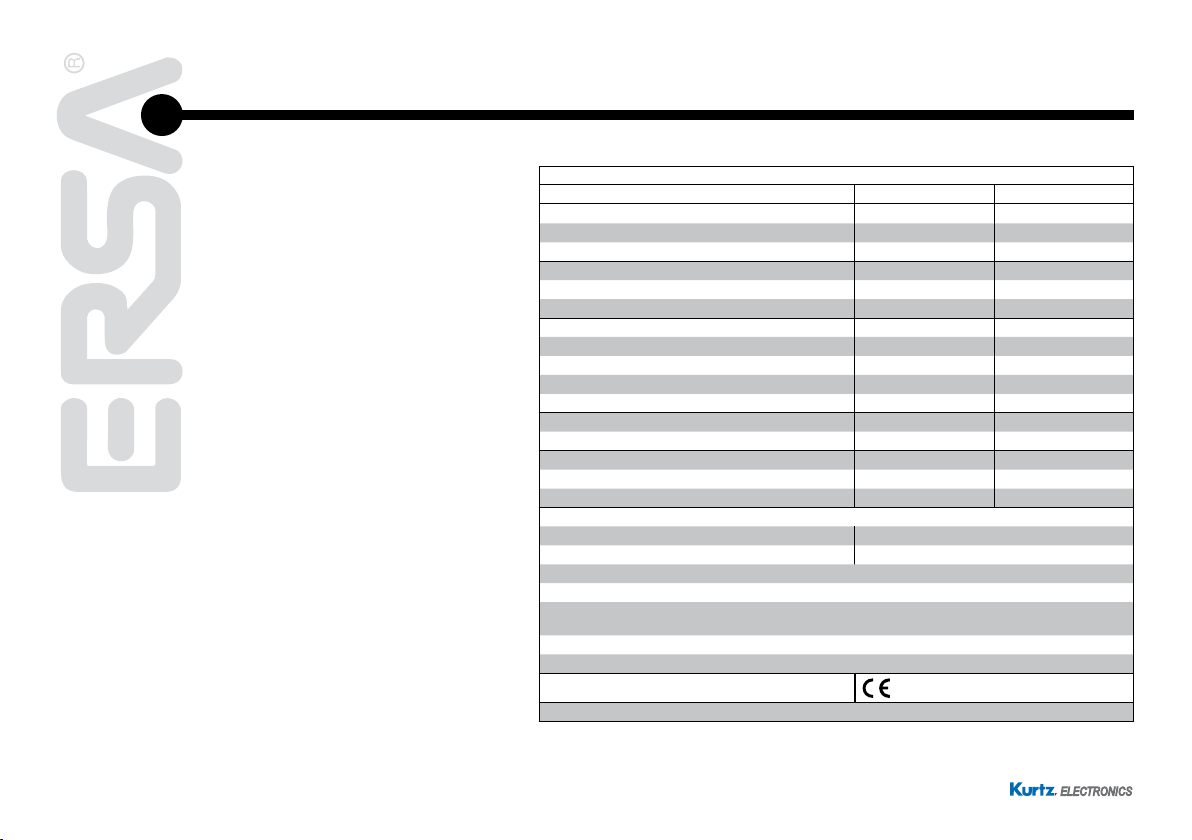
2. Technical data ................................................................................................................ 5
3. For your safety ............................................................................................................... 6
3.1 Pictograph and symbol explanations ..................................................................... 7
3.2 Intended use .......................................................................................................... 8
4. Transport, storage and disposal................................................................................. 11
5. Commissioning ............................................................................................................ 12
5.1 Before starting operation...................................................................................... 12
5.2 Switchingonforthersttime............................................................................... 13
6. Functional description................................................................................................. 14
6.1 Operation ............................................................................................................. 14
6.2 The Work mode ................................................................................................... 15
6.2.1 Software version ..................................................................................... 15
6.3 Parameter mode .................................................................................................. 16
6.3.1 i-Set-Tool................................................................................................. 18
6.3.2 Set temperature ...................................................................................... 19
6.3.3 Calibration temperature .......................................................................... 19
6.3.4 Tip offset ................................................................................................. 20
6.3.5 Calibrating the i-CON 1........................................................................... 20
6.3.6 Calibration temperature .......................................................................... 21
6.3.7 Power Level ............................................................................................ 21
6.3.8 Standby-Time.......................................................................................... 22
6.3.9 Standby-Temperature ............................................................................. 22
6.4 Congurationmode.............................................................................................. 23
6.4.1 Temperature window............................................................................... 24
6.4.2 Process alarm......................................................................................... 24
6.4.3 Password lock......................................................................................... 25
6.4.3.1 Setting the password............................................................. 25
6.4.3.2 Changing the password ........................................................ 27
6.4.3.3 Input of values without deactivating the password................ 27
6.4.3.4 Forgotten password .............................................................. 28

i-CON 1 / 3
3BA00180 • 28.04.2008 • Rev. 1
Contents
6.4.4 Temperature unit..................................................................................... 28
6.4.5 Language selection................................................................................. 28
6.4.6 Adjustable shut-down function (idle state).............................................. 29
6.4.7 Device number........................................................................................ 30
6.5 Factory settings (“default”)................................................................................... 31
6.6 Contrast ............................................................................................................... 32
6.7 Replacing the soldering tip................................................................................... 33
6.7.1 i-Tool ....................................................................................................... 33
6.8 Changing the Heating Element............................................................................ 35
6.8.1 i-Tool ....................................................................................................... 35
6.9 Sensitive components.......................................................................................... 37
7. Error diagnosis and remedy ....................................................................................... 38
7.1 General Errors ..................................................................................................... 38
7.2 Other Errors ......................................................................................................... 39
7.3 Continuity check for i-Tool.................................................................................... 40
7.3.1 Heating element...................................................................................... 40
7.3.2 Thermocouple......................................................................................... 40
7.4 Parameter changes not possible ......................................................................... 40
7.5 Error Messages.................................................................................................... 41
8. Maintenance ................................................................................................................. 43
8.1 Important care jobs .............................................................................................. 43
8.2 Cleaning............................................................................................................... 43
9. Replacement parts....................................................................................................... 44
9.1 ERSADUR Long-Life Soldering tips (i-Tips) ........................................................ 46
10. Warranty........................................................................................................................ 51

i-CON 1 / 4
3BA00180 • 28.04.2008 • Rev. 1
Operatinginstructions
1. Introduction
We appreciate your decision to purchase this high-quality soldering station. The i-
CON 1 from ERSA is a top-of-the-line micro- processor-controlled soldering station.
It is designed for use in industrial production, repairs and in laboratories.
1.1 Supply unit
The use of a microprocessor facilitates operation and sets new standards for the
functions available at the soldering station. Five independent tool settings can be
made and saved for the connected tool by means of a simple menu guide. With the
i-Set Tool (option) it is possible to save these settings. Also you can write back the
saved settings into the soldering station. This way, the basic settings can be trans-
ferred quickly to several soldering stations.
The i-CON 1 was developed for operation of the i-Tool soldering tool. With its vast
variety of functions, the high speed and regulating accuracy this soldering station is
most suitable for use in manufacturing processed with high quality requirements.
The soldering station can optionally be delivered with a serial PC-interface. Control
signals for the soldering smoke extraction EA110 are also available on this interface.

i-CON 1 / 5
3BA00180 • 28.04.2008 • Rev. 1
Operatinginstructions
2. Technical data
Soldering station i-CON 1
Description Value Unit
Mains voltage 220-240 VAC
Mains frequency 50-60 Hz
Fuse (slow-blow) 0,8 A
Mains voltage 110-120 VAC
Mains frequency 50-60 Hz
Fuse (slow-blow) 1,6 A
Secondary voltage 24 VAC
Maximum short-term heating power 150 W
Mean heating power 80 W
Safety class I -
Permissable ambient temperature 0-40 °C
Temperature range (stepless) 150-450 °C
300-842 °F
Temperature regulation (at idle) < ± 2 °C
Ohmic resistance between soldering tip and ground < 2 Ohm
Soldering tip to ground leakage voltage < 2 mV eff
Other
Control technology SENSOTRONIC (PID-behaviour)
Function display LC-Display, blue
Supply line 2m, PVC, with connector
Single-knob control via incremental encoder (i-OP)
Antistatic surface, especially suited for the application in ESD areas. Option: Serial interface to control the
soldering smoke extractor EA110.
In accordance with MIL-SPEC/ESA-standard
VDE*, EMV-tested
Conformity
Connectable soldering tool: i-Tool
*A public safety testing company located in Germany.
Similar in operation to its United States counterpart, UL.

i-CON 1 / 6
3BA00180 • 28.04.2008 • Rev. 1
Operatinginstructions
Soldering iron i-Tool
Description Value Unit
Operating Voltage 24 VAC
Maximum heating power 150 W
Mean heating power 80 W
Heating-up time to 350°C / 662°F approx. 10 sec
Weight (without supply line) approx. 30 g
Other
Supplyline1,2m,highlyexible,heatresistant,antistatic
Type: Antistatic in accordance to MIL-SPEC/ESA-Standard
Thehandlefeaturesanintegratedidenticationandstandbyfunction.
3. For your safety
ERSA products are developed, produced and tested in compliance with the basic
safety requirements.
Nevertheless, residual risks still exist!
For this reason, please read these operating instructions before you operate your
deviceforthersttime.Ithelpsyoutobecomefamiliarwiththedevice‘sfunctions
and to use them optimally. Please store these operating instructions at a place
which is always accessible to all users!

i-CON 1 / 7
3BA00180 • 28.04.2008 • Rev. 1
Operatinginstructions
3.1 Pictograph and symbol explanations
In this instruction manual, pictographs are used as hazard notes.
Special information or orders and prohibitions to prevent personal in-
jury or extensive material damage are supplemented by a pictograph
and in the text with hierarchically structured bold words:
Warning! Is used to warn of an imminent danger. Possible conse-
quences can be death or personal injury.
Attention! Is used to warn of a possible dangerous situation. The
consequences can be personal injury, material or environmental dam-
age.
Caution! Is used for an application recommendation. The conse-
quences of non-observance can be material damage.
In addition to the hierarchic warning notices described above, we use
the following symbols:
This is used to mark text passages which contain explanations, infor-
mation or tips.
■ This sign is used to mark
- activities which you must carry out, or
- instructions which must be followed by all means

i-CON 1 / 8
3BA00180 • 28.04.2008 • Rev. 1
Operatinginstructions
3.2 Intended use
ERSA heating tools may only be used for the processing of soft solder. In special
cases, however, if stated explicitly in the operating manual of the respective tool,
some tools can also be used to work plastics. If the tool is not used as intended or
tampered with, the manufacturer cannot be held liable for any warranty and liability
claims on part of the purchaser.
Attention! Check all components before use. Have any damaged
parts repaired by a specialist or the manufacturer. Incorrectly per-
formed repairs represent a risk of accidents for the user. Always use
genuine ERSA spare parts for any repairs.
Attention! Heating tools get hot. Before heating up the device, check
that the tool insert (e.g. soldering tip, modelling insert, etc.) is cor-
rectly connected to the heating tool. Do not allow the hot tool insert to
touch your skin, your hair or any materials which are heat-sensitive
andammable.Alwaysworkonabasewithadequateheat-resistant
properties.
Attention! Restrict unauthorised access. Make sure that no unauthor-
ized person, in particular children, can get near heating tool without
your permission.
Attention!Dangerofre.Beforeheatinguptheheatingtool,remove
ammableobjects,liquidsandgasesfromtheareawhereyouwillbe
working with your heating tool. Whenever you take a break from your
work, place the heating tool in the holder provided for that purpose.
Disconnect your heating tools from the mains after use.

i-CON 1 / 9
3BA00180 • 28.04.2008 • Rev. 1
Operatinginstructions
Attention! Never leave your hot heating tool unattended. Remember
that the tool insert needs a certain amount of time to cool down to a
safe temperature even after you have switched the device off.
Caution! Keep your workplace tidy. An untidy workplace increases
the risk of accidents.
Attention! Lead alloyed solders are toxic. Solders containing lead are
toxic if they enter human body. For this reason, it is strictly forbidden
to eat, drink or smoke. By equal measure, you should thoroughly wash
your hands after working with lead alloyed solder.
Attention! Dispose of waste solder in a responsible fashion. Comply
with your local authority’s waste disposal regulations when disposing
of the by-products of your soldering work.
Attention! Ventilation and extraction. The materials and ancillary sub-
stances you use whilst soldering can have a detrimental effect on your
health. Make sure there is adequate ventilation or extraction. Comply
with the relevant safety data sheets.

i-CON 1 / 10
3BA00180 • 28.04.2008 • Rev. 1
Operatinginstructions
Warning! Protect connection cables. Do not use the connection cable
to pull out the plug or as a means of carrying the device. Make sure
that connection cables are not exposed to heat and do not come into
contact with oil or sharp edges. Damaged connection cables represent
apotentialcauseofre,short-circuitsandelectricshocks.Damaged
connectingcablescancausere,shortcircuits,andelectricshock,
consequently they must be replaced immediately.
Attention! Take account of ambient conditions. Protect your device
against all liquids and moisture. Failure to do this represents a risk of
reorelectricshocks.
Caution! Look after your heating tool. Always keep your ERSA prod-
uct in a safe, dry place out of the reach of children. Pay attention to
any maintenance requirements. Check your device at regular inter-
vals. Always use genuine ERSA accessories and spare parts.
Attention! Physically and/or mentally disabled people may only use
the soldering station when supervised by trained expert personnel!
Children are not allowed to play with the soldering station!
National and international regulations
Comply with national and international regulations governing health
and safety at work.

i-CON 1 / 11
3BA00180 • 28.04.2008 • Rev. 1
Operatinginstructions
4. Transport, storage and disposal
The i-CON 1 are each delivered in a stable box enclosure. Only use the original
packaging for transport and interim storage of the systems. Do not move jerky or
dropthei-CON1.Thei-CON1mustbeprotectedfromweatherinuencessuch
as rain, fog, sea air, etc. If the units will be stored for a longer period of time under
humid conditions, then the i-CON 1 must be packed air-tight with desiccating agents
in the enclosure. Damages due to improper transport and storage are not covered
by the guarantee.
Disposal Notice in accordance with directive 2002/96/EC of the Euro-
pean Parliament and the council of January 27, 2003 on Waste Elec-
trical and Electronic Equipment (WEEE).
Products labelled with the symbol of the crossed out wheeled bin must
not be disposed of with unsorted municipal waste. For this purpose,
the local authorities have set up collecting points. Please ask your
municipality which possibilities are offered for the separate collection
of WEEE. This way, you make your contribution to the reuse or other
forms of use of WEEE to protect our environment and health.

i-CON 1 / 12
3BA00180 • 28.04.2008 • Rev. 1
Operatinginstructions
5. Commissioning
5.1 Before starting operation
Please check the contents of the packaging for completeness. For more information
read the chapter on [Spare Parts]! Should the listed components be damaged or
incomplete, then please contact your supplier.
The package consists of:
• Electronic station i-CON 1 a
• Soldering iron i-Tool with soldering tip b
• Storage stand with drying sponge c
• Power supply cord
• Operating Instructions
Should the listed components be damaged, then please contact your supplier.

i-CON 1 / 13
3BA00180 • 28.04.2008 • Rev. 1
Operatinginstructions
5.2 Switching on for the first time
Be sure to do the following to ensure the safe and long-lasting operation of the sol-
dering tool:
■ Check whether the supply voltage matches the value stated on the
rating plate.
■ Switch off the soldering station with the power switch a.
■ Checktherighttofthesolderingtip.
■ Connect the soldering tool with the control station band put the sol-
dering iron in the holder.
■ Connect the power cable to the network supply socket c.
■ Switch on the soldering station d.
OFF
_
OFF
_
0_
ON
0_
ON

i-CON 1 / 14
3BA00180 • 28.04.2008 • Rev. 1
Operatinginstructions
6. Functional description
6.1 Operation
The soldering station is switched on and off by the mains switch on the front side a.
The soldering station is controlled via a rotary encoder bwith pushbutton function.
It is called i-OP. The i-OP makes it possible to select desired functions or to change
values. Clockwise turning results in higher values and counter-clockwise turning
in lower values. Slow turning effects change in increments of one. Quick turning
changes the selected values in increments of 10/50/100 (depending on the corre-
sponding parameter).
The i-OP has an additional pushbutton function. Via this pushbutton function (push-
ing),theselectedparametersandvaluesareconrmedandbecomeeffectivefor
the station. All setting steps and measured values are displayed in plain text in a
clearly structured display window, which is simply referred to as “Display”.
0_
ON
0_
ON

i-CON 1 / 15
3BA00180 • 28.04.2008 • Rev. 1
Operatinginstructions
6.2 The Work mode
After the station has been switched on, the switch-on dialog is displayed for approx.
2 seconds. This dialog shows the station name aand the software version bof
the i-CON 1. The station will then automatically change to work mode with the pa-
rameters:
• actual value c
• set value and possibly standby status d
• connected soldering tool (i-Tool in our example) e
• password lock active (KEY-symbol) f
In the work mode, the soldering tip temperature can be directly changed by turning
thei-OP.Conrmthisbypushingthei-OP.
If the password lock is activated, the set value can only be changed
via the parameter mode. The password is needed.
6.2.1 Software version
Theseoperatinginstructionsrefertormware2.16.Forservicepurposesthe
number of the software may be of help, you should therefore make a note of it and
keep it ready, as you may need it when asked by our Service Department.

i-CON 1 / 16
3BA00180 • 28.04.2008 • Rev. 1
Operatinginstructions
6.3 Parameter mode
The following settings can be made in parameter mode:
• Nominal temperature (150-450°C/302-842°F)
• Calibration temperature (-70…+50°C/-126…+90°F)
• Tip offset (Function reserved)
• Energy function (3 stages)
• Standby-Time (0-60min)
• Standby-Temperature (150-300°C).
Please proceed as follows to activate the parameter mode:
■ Hold the i-OP depressed for about 2 seconds, or press the i-OP two
times quickly in succession.
The parameter mode is now activated. The desired parameter is selected by turning
on the i-OP.
For the selected parameter a, a help text bis displayed in the last line which gives
additional explanations or numerical ranges.

i-CON 1 / 17
3BA00180 • 28.04.2008 • Rev. 1
Operatinginstructions
Proceed as follows in order to change a parameter value:
■ Push the i-OP for approx. 2 sec. or two times quickly in succession to
open the parameter mode.
■ Select the desired parameter by turning the i-OP.
■ Press the i-OP to activate the cursor, pressing the i-OP subsequently
de-activates the cursor.
If the cursor is activated, the value of the parameter is changed accordingly when
the i-OP is turned. If the i-OP is pushed twice, the parameter mode can be called up
or left directly.

i-CON 1 / 18
3BA00180 • 28.04.2008 • Rev. 1
Operatinginstructions
6.3.1 i-Set-Tool
With the i-Set Tool (option) it is possible to save the settings (including password)
of the station. Also you can write back the saved settings into the station. This way,
the basic settings can be transferred quickly to several soldering stations. Please
observe the i-Set Tool´s manual for this purpose. How to use the i-Set Tool:
■ Disconnect the soldering tool from the soldering station and connect
the i-Set Tool.
■ Turn the i-OP and select the following: Upload: The data of the station
is written into the i-Set Tool. Download: The data of the i-Set Tool is
written into the station. Then, push the i-OP.
Aconrmationpromptisdisplayed:
■ Select [Abort] to end the process or [>>>] to continue.
■ Push the i-OP; the settings will be saved. Wait until the text [Param-
eter saved] is displayed. Then, remove the i-Set Tool.
Display contrast, calibration and offset are not transferred. When
transferring data to the soldering station, the parameters for all solder-
ing tools will be overwritten. Take note of this when you operate differ-
ent soldering tools at your soldering stations.
Even though the soldering station is equipped with a serial PC-inter-
face (option), the device number of the station is not transmitted.

i-CON 1 / 19
3BA00180 • 28.04.2008 • Rev. 1
Operatinginstructions
6.3.2 Set temperature
The set temperature is the desired soldering tip temperature.
In the work mode, the soldering tip temperature can be directly
changedbyturningthei-OP.Conrmthisbypushingthei-OP.
6.3.3 Calibration temperature
Use this function to calibrate the soldering tip temperature. It makes it possible to
adjust the display value and actual tip temperature. The adjustable calibration range
is -70...+50°C/-126...+90°F.
The exact calibration procedure is described in chapter 6.3.5. “i-CON 1 Calibration”.
If you do not have a corresponding measuring unit for this measure-
ment,pleaseenter“0”intothisparametereld.

i-CON 1 / 20
3BA00180 • 28.04.2008 • Rev. 1
Operatinginstructions
6.3.4 Tip offset
(Function reserved)
6.3.5 Calibrating the i-CON 1
Use the calibration temperature (see 6.3.6 “Calibration” temperature) to exactly syn-
chronize the actual tip temperature with the displayed temperature. The following
procedure must be observed for the calibration:
■ Input of desired set temperature (Chapter 6.3.2 “Set temperature”).
■ Set the calibration temperature (Chapter 6.3.6 “Determination of cali-
bration temperature”).
This manual suits for next models
1
Table of contents
Other ersa Soldering Gun manuals

ersa
ersa ANALOG 60 User manual

ersa
ersa DIGITAL 2000 A User manual

ersa
ersa RA 4500 D User manual

ersa
ersa Solder Smart User manual

ersa
ersa i-CON NANO MK2 User manual

ersa
ersa DIGITAL 2000 A User manual

ersa
ersa i-CON 1V User manual

ersa
ersa i-CON NANO MK2 User manual

ersa
ersa i-CON 1V User manual

ersa
ersa RDS 80 User manual