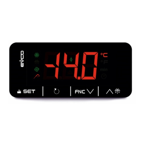
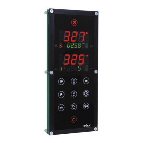
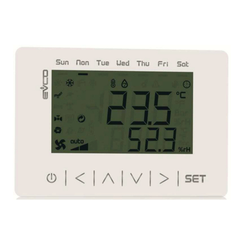
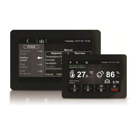
Evco c-pro 3 micro AHU User manual

EVCO S.p.A. c-pro 3 micro and c-pro 3 kilo | Hardware manual ver. 1.1 | Code 114CP3UKE114
page 1 of 62
c-pro 3 micro and c-pro 3 kilo
PROGRAMMABLE CONTROLLERS
ENGLISH
HARDWARE MANUAL ver. 1.1
CODE 114CP3UKE114

EVCO S.p.A. | Via Feltre 81, 32036 Sedico (BL) ITALY | phone +39 0 37 8 22 | fax +39 0 37 836 8 | email inf[email protected] | web www.evco.it
VAT number IT00769310251 page 1 of 1
Date: 22
nd
February 2022
Pages: 1 of 1
From: EVCO S.p.A.
To: - Internal sales force
- Branches
- Customers
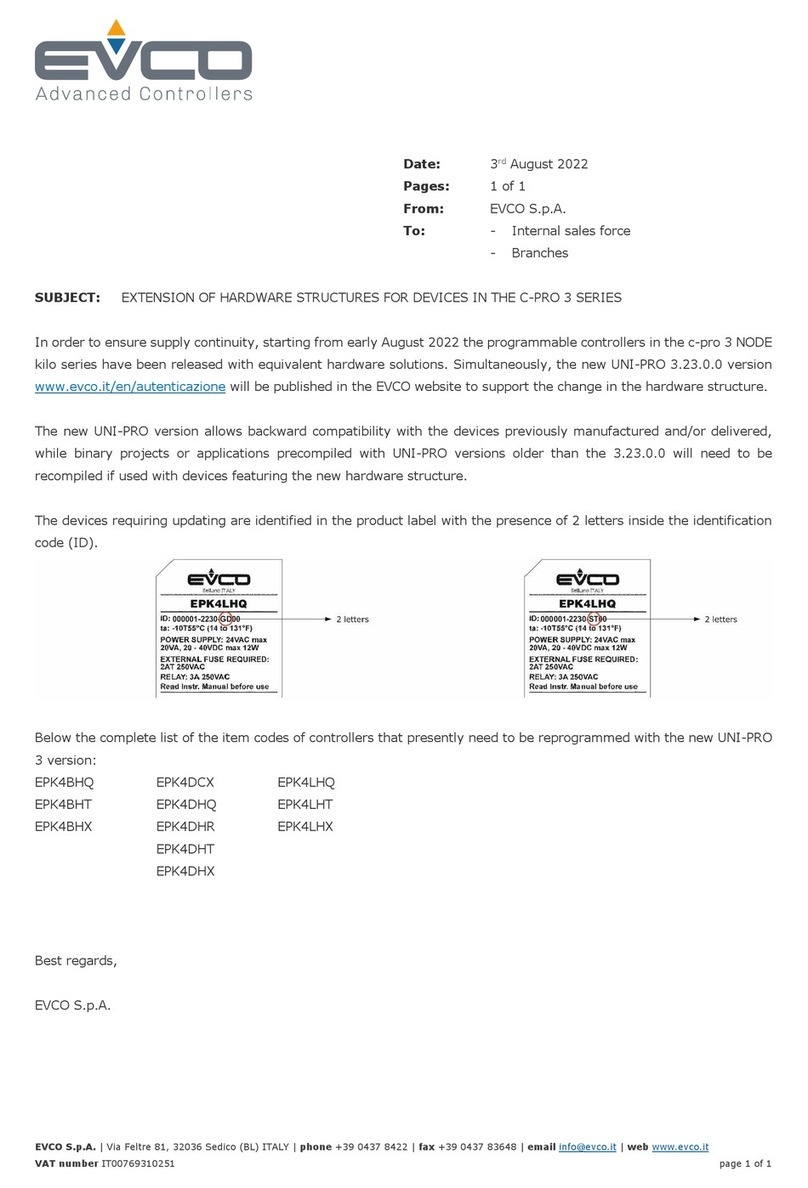
S BJECT: EXTENSION OF HARDWARE STRUCTURES FOR PROGRAMMABLE CONTROLLERS AND USER INTERFACES
IN THE C-PRO 3 SERIES
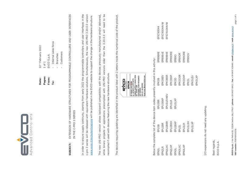
In order to ensure supply continuity, starting from early 2022 the programmable controllers and user interfaces in the
c-pro 3 series will be released with equivalent hardware solutions. Simultaneously, the new UNI-PRO 3.20.0.0 version
www.evco.it/en/autenticazione will be published in the EVCO website to support the change in the hardware structure.
The new UNI-PRO version allows backward compatibility with the devices previously manufactured and/or delivered,
while binary projects or applications precompiled with UNI-PRO versions older than the 3.20.0.0 will need to be
recompiled if used with devices featuring the new hardware structure.
The devices requiring updating are identified in the product label with 2 letters inside the numerical code of the product.
Below the complete list of the device item codes presently involved in this activity:
EPN2L EPU2B EPU3BR EPK3B EPB9BRE EPJC900X
EPN2LR EPU2BR EPU3BXP EPK3BEV EPB9BVE EPJC900X VW
EPN2LXC EPU2BSR EPU3LEV EV EPK3BSR EPB9BXE EPJC910X VW
EPN2LXP EPU2BXH EPU3LR EPK3BXP EPB9DRE
EPN3L EPU2BXP EPU3LXP EPK3D EPB9O
EPN3LXC EPU2L EPK3DSR EPB9OR
EPN3LXP EPU2LR EPK3DXP EPB9ORE
EPU2LXH EPK3L EPB9OV
EPU2LXP EPK3LEV
EPK3LXP
I/O expansions do not need any updating.
Best regards,
EVCO S.p.A.

EVCO S.p.A. c-pro 3 micro and c-pro 3 kilo | Hardware manual ver. 1.0 | Code 114CP3UKE104
page 2 of 62
Important
Important
Read this document carefully before the installation and before the use and follow all the additional information for the installation and
for the electrical connection; keep this document close to the devices for future consultations.
The following symbols support the reading of the document:
it indicates a suggestion
it indicates an additional information to be followed.
The devices must be disposed according to the local legislation about the collection for electrical and electronic equipment.

EVCO S.p.A. c-pro 3 micro and c-pro 3 kilo | Hardware manual ver. 1.0 | Code 114CP3UKE104
page 3 of 62
Index
1.
INTRODUCTION.......................................................................................................................................................................5
1.1.
Introduction................................................................................................................................................................................5
2.
DESCRIPTION..........................................................................................................................................................................6
2.1.
Description programmable controllers........................................................................................................................................6
2.2.
Description I/O expansions........................................................................................................................................................8
3.
SIZE AND INSTALLATION........................................................................................................................................................9
3.1.
Size programmable controllers...................................................................................................................................................9
3.2.
Size I/O expansions...................................................................................................................................................................9
3.3.
Installation ...............................................................................................................................................................................10
3.4.
Additional information for installation........................................................................................................................................10
4.
ELECTRICAL CONNECTION..................................................................................................................................................11
4.1.
Connectors programmable controllers .....................................................................................................................................11
4.2.
Connectors I/O expansions......................................................................................................................................................13
4.3.
Meaning of connectors.............................................................................................................................................................15
4.3.1.
Example of electrical connection....................................................................................................................................23
4.4.
Additional information for electrical connection.........................................................................................................................24
5.
USER INTERFACE..................................................................................................................................................................25
5.1.
Keyboard.................................................................................................................................................................................25
5.2.
Signalling LEDs .......................................................................................................................................................................25
5.2.1.
LEDs at the front of the device.......................................................................................................................................25
6.
CONFIGURATION...................................................................................................................................................................27
6.1.
Configuring a programmable controller ....................................................................................................................................27
6.1.1.
Configuring a built-in programmable controller...............................................................................................................27
6.1.2.
Configuring a blind programmable controller ..................................................................................................................29
6.2.
Configuring an I / O expansion.................................................................................................................................................30
6.3.
Configuring a device through an user interface (Vgraph, Vtouch, Vroom or Vcolor) ................................................................31
6.4.
List of configuration parameters...............................................................................................................................................32
7.
USER INTERFACES...............................................................................................................................................................46
7.1.
Preliminary information............................................................................................................................................................46
7.2.
Vgraph.....................................................................................................................................................................................46
7.2.1.
Introduction....................................................................................................................................................................46
7.2.2.
Summarizing table of the main features and available models........................................................................................46
7.2.3.
Size................................................................................................................................................................................47
7.3.
Vtouch.....................................................................................................................................................................................48
7.3.1.
Introduction....................................................................................................................................................................48
7.3.2.
Summarizing table of the main features and available models........................................................................................48
7.3.3.
Size................................................................................................................................................................................49
7.4.
Vroom......................................................................................................................................................................................50
7.4.1.
Introduction....................................................................................................................................................................50
7.4.2.
Summarizing table of the main features and available models........................................................................................50
7.4.3.
Size................................................................................................................................................................................51
7.5.
Vcolor......................................................................................................................................................................................52
7.5.1.
Introduction....................................................................................................................................................................52
7.5.2.
Summarizing table of the main features and available models........................................................................................52
7.5.3.
Size................................................................................................................................................................................53
8.
TECHNICAL DATA..................................................................................................................................................................54
8.1.
Technical data .........................................................................................................................................................................54

EVCO S.p.A. c-pro 3 micro and c-pro 3 kilo | Hardware manual ver. 1.0 | Code 114CP3UKE104
page 5 of 62
1. INTRODUCTION
1.1. Introduction
c-pro 3 micro and c-pro 3 kilo are two families of programmable controllers.
The family consists of:
- programmable controllers (c-pro 3 micro, c-pro 3 micro+, c-pro 3 kilo and c-pro 3 kilo+)
- I / O expansions (c-pro 3 EXP micro, c-pro 3 EXP micro+, c-pro 3 EXP kilo and c-pro 3 EXP kilo+).
c-pro 3 micro and c-pro 3 micro+ are available in the following versions:
- with 4 + 4 digits custom LED display (with function icons) and with a 6 buttons (with preset functions) keyboard made of
silicone rubber integrated in the controller, hereinafter also called “built-in LED versions”
- blind (they can be used for example with an user interface such as Vgraph, Vtouch, Vroom or Vcolor), hereinafter also
called “blind versions”.
c-pro 3 kilo and c-pro 3 kilo+ are available in the following versions:
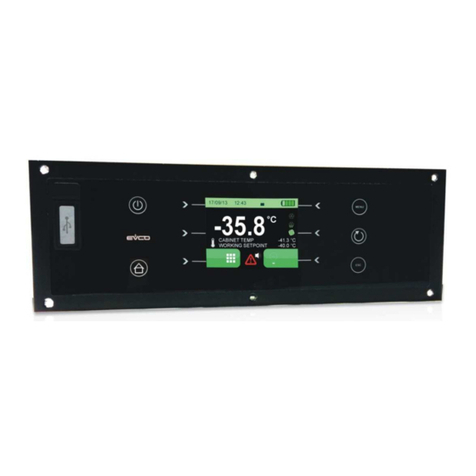
- with 128 x 64 pixel single colour LCD graphic display (black with rearlighting through white LEDs) and with a 6 buttons (with
preset functions) keyboard made of silicone rubber integrated in the controller, hereinafter also called “built-in LCD versions”
- with 4 + 4 digits custom LED display (with function icons) and with a 6 buttons (with preset functions) keyboard made of
silicone rubber integrated in the controller, hereinafter also called “built-in LED versions”
- blind (they can be used for example with an user interface such as Vgraph, Vtouch, Vroom or Vcolor), hereinafter also
called “blind versions”.
Some integrate an unipolar stepper electronic expansion valves driver.
The I/O expansions are available in blind version.
Through the development environment UNI-PRO 3 (to order separately) it is possible to realize the application software and through a
commun USB cable it is possible to program the controllers.
The devices look in case 4 DIN modules; installation is in electrical panel, on DIN rail.
Through a common USB peripheral it is possible to make the upload and the download of the configuration parameters.

EVCO S.p.A. c-pro 3 micro and c-pro 3 kilo | Hardware manual ver. 1.0 | Code 114CP3UKE104
page 6 of 62
2. DESCRIPTION
2.1. Description programmable controllers
The following drawing shows the aspect of the programmable controllers.
The following table shows the meaning of the parts of the controller.
Part Meaning
1 digital outputs 6 and 7
2 digital outputs 1 and 5
3
according to the model:
- digital outputs 9 (available in models c-pro 3 micro+ and c-pro 3 kilo+ only)
- unipolar stepper electronic expansion valves driver (available in models c-pro 3 micro+ and c-pro 3 kilo+
only)
4 display and keyboard (not available in the blind versions)
5 analog inputs 7... 9, digital inputs 6... 9 and analog outputs 4... 6 (available in models c-pro 3 micro+ and c-pro 3
kilo+ only)
6 analog inputs 1... 6, digital inputs 1... 5 and analog outputs 1... 3
7 OTG USB port
8
micro-switch to:
- plug in the termination of the RS-485 port with Modbus slave communication protocol
- plug in the termination of the CAN port
9 power supply, RS-485 port with Modbus master communication protocol and CAN port

EVCO S.p.A. c-pro 3 micro and c-pro 3 kilo | Hardware manual ver. 1.0 | Code 114CP3UKE104
page 7 of 62
10 RS-485 port with Modbus master communication protocol (available in models c-pro 3 micro+ and c-pro 3 kilo+
only)
11 micro-switch to plug in the termination of the RS-485 port with Modbus master communication protocol (available in
models c-pro 3 micro+ and c-pro 3 kilo+ only)
12 signalling LEDs
13
according to the model:
- digital outputs 8 (available in models c-pro 3 micro+ and c-pro 3 kilo+ only)
- unipolar stepper electronic expansion valves driver (available in models c-pro 3 micro+ and c-pro 3 kilo+
only)

EVCO S.p.A. c-pro 3 micro and c-pro 3 kilo | Hardware manual ver. 1.0 | Code 114CP3UKE104
page 8 of 62
2.2. Description I/O expansions
The following drawing shows the aspect of the I/O expansions.
The following table shows the meaning of the parts of the expansion.
Part Meaning
1 digital outputs 6 and 7
2 digital outputs 1 and 5
3 digital outputs 9 (available in models c-pro 3 EXP micro+ and c-pro 3 EXP kilo+ only)
4 analog inputs 7... 9, digital inputs 6... 9 and analog outputs 4... 6 (available in models c-pro 3 EXP micro+ and
c-pro 3 EXP kilo+ only)
5 analog inputs 1... 6, digital inputs 1... 5 and analog outputs 1... 3
6 OTG USB port
7 micro-switch to plug in the termination of the CAN port
8 power supply and CAN port
9 signalling LEDs
10 digital outputs 8 (available in models c-pro 3 EXP micro+ and c-pro 3 EXP kilo+ only)

EVCO S.p.A. c-pro 3 micro and c-pro 3 kilo | Hardware manual ver. 1.0 | Code 114CP3UKE104
page 9 of 62
3. SIZE AND INSTALLATION
3.1. Size programmable controllers
4 DIN modules; size in mm (in).
3.2. Size I/O expansions
4 DIN modules; size in mm (in).

EVCO S.p.A. c-pro 3 micro and c-pro 3 kilo | Hardware manual ver. 1.0 | Code 114CP3UKE104
page 10 of 62
3.3. Installation
On DIN rail 35.0 x 7.5 mm (1.377 x 0.295 in) or 35.0 x 15.0 mm (1.377 x 0.590 in).
To install the devices operate as shown in the following drawing.
12
To remove the devices remove possible extractable screw terminal blocks plugged at the bottom first, then operate on the DIN rail clips
with a screwdriver as shown in the following drawing.
34
To install the devices again press the DIN rail clips to the end first.
3.4. Additional information for installation
- working conditions (working temperature, humidity, etc.) must be between the limits indicated in the technical data
- do not install the devices close to heating sources (heaters, hot air ducts, etc.), equipments provided with big magnetos (big
speakers, etc.), locations subject to direct sunlight, rain, humidity, dust, mechanical vibrations or bumps
- according to the safety legislation, the protection against electrical parts must be ensured by a correct installation of the
devices; the parts that ensure the protection must be installed so that you can not remove them if not by using a tool.

EVCO S.p.A. c-pro 3 micro and c-pro 3 kilo | Hardware manual ver. 1.0 | Code 114CP3UKE104
page 11 of 62
4. ELECTRICAL CONNECTION
4.1. Connectors programmable controllers
The following drawing shows the connectors of c-pro 3 micro and of c-pro 3 kilo.
The following drawing shows the connectors of c-pro 3 micro+ and of c-pro 3 kilo+.
Models with 9 electromechanical relays

EVCO S.p.A. c-pro 3 micro and c-pro 3 kilo | Hardware manual ver. 1.0 | Code 114CP3UKE104
page 12 of 62
Models with 7 electromechanical relays and 2 solid state relays
Models with integrated unipolar stepper electronic expansion valves driver

EVCO S.p.A. c-pro 3 micro and c-pro 3 kilo | Hardware manual ver. 1.0 | Code 114CP3UKE104
page 13 of 62
4.2. Connectors I/O expansions
The following drawing shows the connectors of c-pro 3 EXP micro and of c-pro 3 EXP kilo.
The following drawing shows the connectors of c-pro 3 EXP micro+ and of c-pro 3 EXP kilo+.
Models with 9 electromechanical relays

EVCO S.p.A. c-pro 3 micro and c-pro 3 kilo | Hardware manual ver. 1.0 | Code 114CP3UKE104
page 14 of 62
Models with 7 electromechanical relays and 2 solid state relays

EVCO S.p.A. c-pro 3 micro and c-pro 3 kilo | Hardware manual ver. 1.0 | Code 114CP3UKE104
page 15 of 62
4.3. Meaning of connectors
The following tables show the meaning of the connectors.
Digital outputs 1… 7
Electromechanical relays.
Terminal Meaning
NO6 normally open contact digital output 6 (3 res. A @ 250 VAC)
NO7 normally closed contact digital output 7 (3 res. A @ 250 VAC)
CO6/7 common digital outputs 6 and 7
Terminal Meaning
NO1 normally open contact digital output 1 (3 res. A @ 250 VAC)
NO2 normally open contact digital output 2 (3 res. A @ 250 VAC)
CO1/2 common digital outputs 1 and 2
NO3 normally open contact digital output 3 (3 res. A @ 250 VAC)
NO4 normally open contact digital output 4 (3 res. A @ 250 VAC)
NO5 normally open contact digital output 5 (3 res. A @ 250 VAC)
CO3/4/5 common digital outputs 3, 4 and 5
The maximum length of the connecting cables of the digital outputs is 100 m (328 ft).
Digital outputs 8 and 9
According to the model, electromechanical or solid state relays.
Terminal Meaning
CO8 common digital output 8
NO8 normally open contact digital output 8 (3 res. A @ 250 VAC in case of electromechanical relay; 24 VAC/DC, 0,6 A
max in case of solid state relay)
NC8 normally closed contact digital output 8
Terminal Meaning
CO9 common digital output 9

EVCO S.p.A. c-pro 3 micro and c-pro 3 kilo | Hardware manual ver. 1.0 | Code 114CP3UKE104
page 16 of 62
NO9 normally open contact digital output 9 (3 res. A @ 250 VAC in case of electromechanical relay; 24 VAC/DC, 0,6 A
max in case of solid state relay)
NC9 normally closed contact digital output 9
The maximum length of the connecting cables is:
- 100 m (328 ft) in case of electromechanical relay
- 100 m (328 ft) in case of solid state relay.
Unipolar stepper electronic expansion valves driver
The following drawing shows the connectors of the unipolar stepper electronic expansion valves driver.
The following table shows the meaning of the connectors.
Terminal Meaning
SOA unipolar stepper motor coli 1
SOB unipolar stepper motor coli 2
SOC unipolar stepper motor coli 3
SOD unipolar stepper motor coli 4
COM12V motor power supply (12 VDC, 260 mA max.)
The maximum length of the connecting cables is 3 m (9,842 ft).

EVCO S.p.A. c-pro 3 micro and c-pro 3 kilo | Hardware manual ver. 1.0 | Code 114CP3UKE104
page 17 of 62
RS-485 port
RS-485 port with Modbus master communication protocol (with network already polarized internally).
Terminal Meaning
GND ground
A / + terminal 1 of the transceiver
B / - terminal 0 of the transceiver
The maximum length of the connecting cables of the RS-485 port is 1,000 m (3,280 ft); also look at the Modbus specifications
and implementation guides manual (the document is available on the internet site www.modbus.org).
Connect the RS-485 port using a twisted pair.
The following table shows the function codes supported by the controller.
Function
code Meaning
FC 01 read coils
FC 02 read discrete inputs
FC 03 read multiple registers
FC 04 read input registers
FC 05 write single coil
FC 06 write single register
FC 08 diagnostic
FC 15 write multiple coils
FC 16 write multiple registers
FC 23 read write multiple registers
For the settings about the RS-485 port look at chapter 6 “CONFIGURATION”.
Termination RS-485 port
Micro-switch to plug in the termination of the RS-485 port with Modbus master communication protocol (120 Ω, 0.25 W); position micro-
switch 1 on position ON to plug in the termination of the RS-485 port (plug in the termination of the first and of the last element of the
network).

EVCO S.p.A. c-pro 3 micro and c-pro 3 kilo | Hardware manual ver. 1.0 | Code 114CP3UKE104
page 18 of 62
Analog inputs 7... 9, digital inputs 6... 9 and analog outputs 4... 6
Terminal Meaning
GND common analog inputs and analog outputs
AI7 analog input 7 (configurable via configuration parameter for PTC / NTC / Pt 1000 probes / 0-20 mA / 4-20 mA / 0-5 V
ratiometric / 0-10 V transducers)
AI8 analog input 8 (configurable via configuration parameter for PTC / NTC / Pt 1000 probes / 0-20 mA / 4-20 mA / 0-5 V
ratiometric / 0-10 V transducers)
AI9 analog input 9 (configurable via configuration parameter for PTC / NTC / Pt 1000 probes / 0-20 mA / 4-20 mA / 0-5 V
ratiometric / 0-10 V transducers)
AO4 analog output 4 (configurable via configuration parameter for 0-20 mA / 4-20 mA / 0-10 V signal)
AO5 analog output 5 (for 0-10 V signal)
AO6 analog output 6 (for 0-10 V signal)
DI6 digital input 6 (optoisolated, 24 VAC / DC and 50 / 60 Hz)
DI7 digital input 7 (optoisolated, 24 VAC / DC and 50 / 60 Hz)
DI8 digital input 8 (optoisolated, 24 VAC / DC and 50 / 60 Hz)
DI9 digital input 9 (optoisolated, 24 VAC / DC and 50 / 60 Hz)
COM common digital inputs
The maximum length of the connecting cables is:
- 100 m (328 ft) for the analog inputs
- 100 m (328 ft) for the digital inputs
- 100 m (328 ft) for the analog outputs.
For the settings about the analog inputs look at chapter 6 “CONFIGURATION”.

EVCO S.p.A. c-pro 3 micro and c-pro 3 kilo | Hardware manual ver. 1.0 | Code 114CP3UKE104
page 19 of 62
Power supply, RS-485 port with Modbus slave communication protocol and CAN port
Terminal Meaning
V≅ + power supply controller (12 VAC in c-pro 3 micro and in c-pro 3 micro+, 24 VAC / 20... 30 VDC in c-pro 3 kilo and in
c-pro 3 kilo+); if the controller is powered in alternating current, connect the phase
V≅ - power supply controller (12 VAC in c-pro 3 micro and in c-pro 3 micro+, 24 VAC / 20... 30 VDC in c-pro 3 kilo and in
c-pro 3 kilo+); if the controller is powered in alternating current, connect the neutral
A / + terminal 1 of the transceiver RS-485 port
B / - terminal 0 of the transceiver RS-485 port
CAN + signal + CAN port
CAN - signal - CAN port
The maximum length of the connecting cables is:
- 100 m (328 ft) for the power supply
- 1,000 m (3,280 ft) for the RS-485 port; also look at the Modbus specifications and implementation guides manual
(the document is available on the internet site www.modbus.org).
The maximum length of the connecting cables of the CAN port depends on the baud rate of the CANbus communication, as
follows:
- 1,000 m (3,280 ft) with baud rate 20,000 baud
- 500 m (1,640 ft) with baud rate 50,000 baud
- 250 m (820 ft) with baud rate 125,000 baud
- 50 m (164 ft) with baud rate 500,000 baud.
Protect the power supply with a fuse rated 2 A-T 250 V.
If the controller is powered in direct current, it will be necessary to respect the polarity of the power supply voltage.
In case of connection in a network:
- for the devices powered at 12 VAC, the power supply of the devices in the network must be galvanically isolated one another
- for the devices powered at 24 VAC, it is necessary the phase powering the device is the same powering the remaining
devices in the network
- for the devices powered at 20... 30 VDC, it is necessary to recpect the polarity ot the power supply voltage of all the devices in
the network.
Connect the RS-485 port using a twisted pair.

EVCO S.p.A. c-pro 3 micro and c-pro 3 kilo | Hardware manual ver. 1.0 | Code 114CP3UKE104
page 20 of 62
The following table shows the function codes supported by the controller.
Function
code Meaning
FC 01 read coils
FC 02 read discrete inputs
FC 03 read multiple registers
FC 04 read input registers
FC 05 write single coil
FC 06 write single register
FC 08 diagnostic
FC 15 write multiple coils
FC 16 write multiple registers
FC 23 read write multiple registers
For the settings about the RS-485 port look at chapter 6 “CONFIGURATION”.
The maximum number of devices that can make a CAN network (32) depends on the bus load; the bus load depends on the baud rate
of the CANbus communication and on the kind of device in the network.
For example: a CAN network can be made of a programmable controller, of four I / O expansions and of four user interfaces
with baud rate 500,000 baud.
Connect the CAN port using a twisted pair.
For the settings about the CAN port look at chapter 6 “CONFIGURATION”.
Termination RS-485 port and termination CAN port
Micro-switch to:
- plug in the termination of the CAN port (120 Ω, 0,5 W); position micro-switch 2 on position ON to plug in the termination of the
CAN port (plug in the termination of the first and of the last element of the network).
- to plug in the termination of the RS-485 port with Modbus slave communication protocol (120 Ω, 0.25 W); position micro-
switch 1 on position ON to plug in the termination of the RS-485 port (plug in the termination of the first and of the last element
of the network).
Other manuals for c-pro 3 micro AHU
2
This manual suits for next models
2
Table of contents
Other Evco Controllers manuals

Evco
Evco EVJ 200 User manual

Evco
Evco EV3 Basic Split User manual

Evco
Evco C-pro 3 giga User manual

Evco
Evco C-pro 3 giga User manual

Evco
Evco c-pro 3 OEM User manual

Evco
Evco Vcolor 229 M Series User manual

Evco
Evco EVJ 700 User guide

Evco
Evco EVXV 800 Series User guide

Evco
Evco EV3 MVC Series Instructions for use

Evco
Evco EVD HP User guide