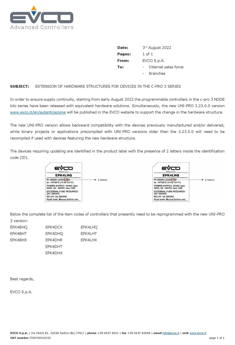
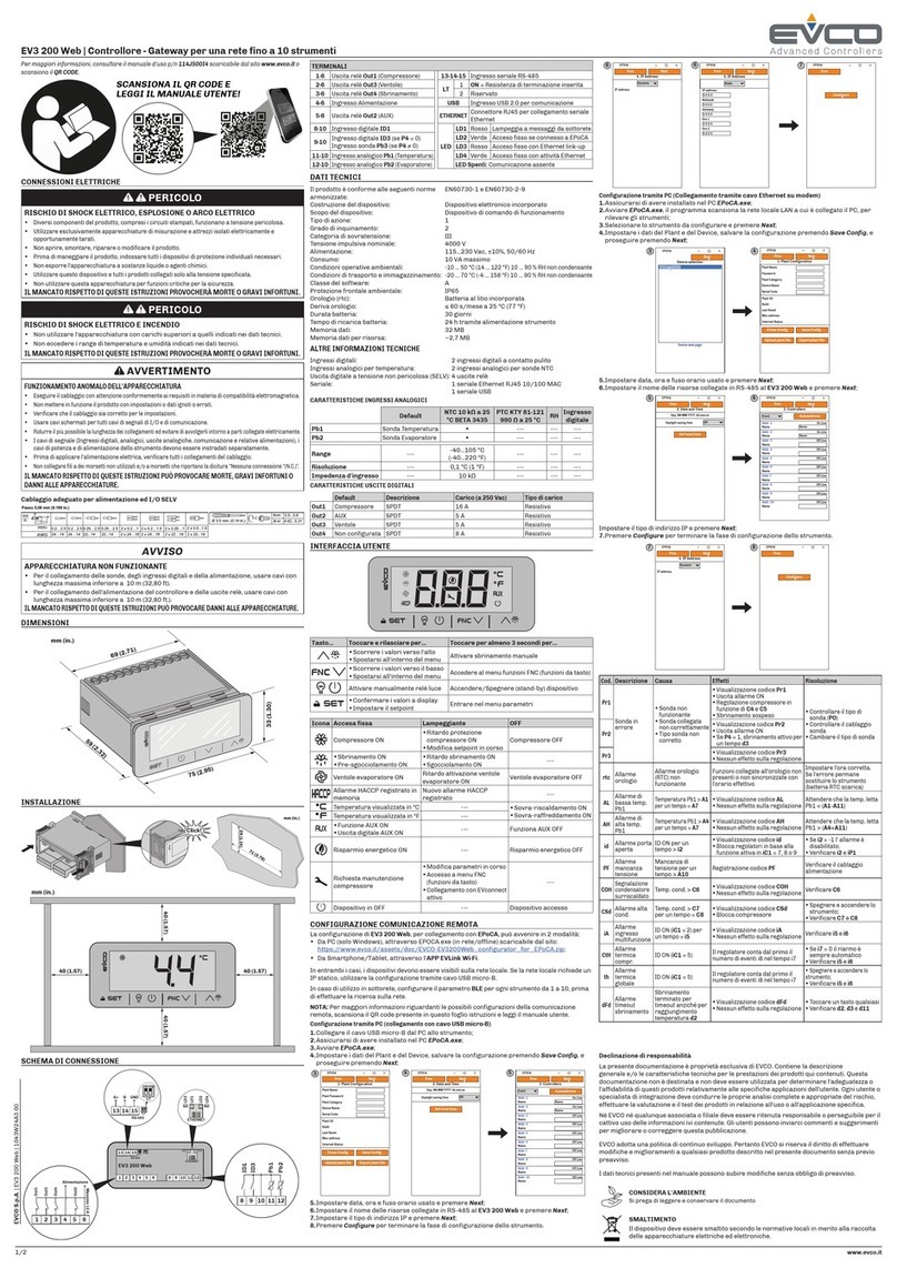
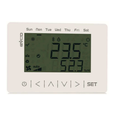
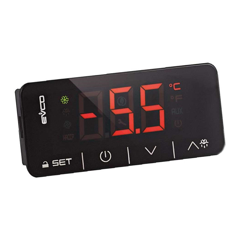
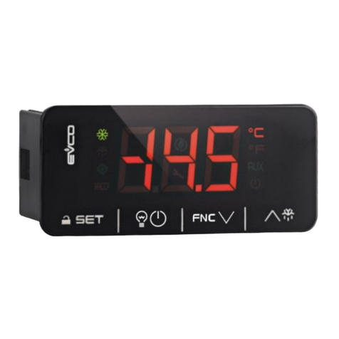
Evco C-PRO NANO User manual

C-PRO NANO
PROGRAMMABLE CONTROLLERS
HARDWARE MANUAL
CODICE 114CPRNHWE03

C-PRO NANO HARDWARE MANUAL
Page 2
Important
Please read these instructions carefully prior to installation and use, and follow all the precautions for installation and electrical
connections; keep these instructions with the device for future consultation.
The device must be disposed of in accordance with local regulations pertaining to the collection of electrical and electronic
appliances.

C-PRO NANO HARDWARE MANUAL
Page 3
Contents
1INTRODUCTION........................................................................................................................................ 4
2COMPONENT AND AUXILIARY NETWORK SYSTEMS.................................................................. 5
3TECHNICAL CHARACTERISTICS........................................................................................................ 6
3.1 C
ONNECTIONS
......................................................................................................................................... 6
3.2 T
HE
C-PRO
NANO
WIRING LAYOUT
...................................................................................................... 8
3.3 C-PRO
NANO
DIMENSIONS
/
INSTALLATION
......................................................................................... 10
3.4 G
ENERAL CHARACTERISTICS
................................................................................................................. 11
3.5 T
ECHNICAL CHARACTERISTICS
.............................................................................................................. 11
3.6 E
LECTRICAL CHARACTERISTICS
............................................................................................................. 12
4THE C-PRO NANO USER INTERFACE............................................................................................... 14
5C-PRO EXP MICRO I/O EXPANSION UNITS..................................................................................... 16
5.1 T
HE
C-PRO
EXP
MICRO
WIRING LAYOUT
.......................................................................................... 17
5.2 C-PRO
EXP
MICRO
DIMENSIONS
/
INSTALLATION
................................................................................ 19
6ACCESSORIES.......................................................................................................................................... 19
6.1 U
SER TERMINALS
.................................................................................................................................. 19
6.1.1 V LEDi dimensions and installation............................................................................................. 20
6.1.2 V WALL dimensions and installation........................................................................................... 22
6.2 EVDFAN1
CUT
-
OFF SPEED REGULATOR
............................................................................................... 29
6.3 A
CCESSORIES FOR SUPERVISION AND MONITORING
............................................................................... 31
6.3.1 Non-insulated TTL/RS485 interface............................................................................................. 31
6.3.2 Insulated TTL/RS485 interface..................................................................................................... 31
6.4 P
ROGRAMMING ACCESSORIES
................................................................................................................ 33
6.4.1 EVKEY programming key............................................................................................................. 33
6.4.2 EVPROG programming kit........................................................................................................... 33

C-PRO NANO HARDWARE MANUAL
Page 4
1Introduction
The C-PRO NANO family of programmable controllers is the ideal solution for refrigeration, ventilation and
air conditioning applications in low complexity situations. Both in terms of regulation operations and the user
interface, the controller software is fully programmable, in a simple and intuitive manner, thanks to the use of
the UNI-PRO development environment.
The C-PRO NANO is manufactured as a panel installation version.
Using the 6 relay outputs, it is possible to control various types of devices such as compressors, water
circulation pumps, defrosting elements, condensation or evaporation fans, cycle inversion valves, alarm
warning indicators etc. The control process makes use of NTC probes for monitoring temperature and
0/4-20 mA or 0-5V ratiometric transducers for monitoring pressure. There are two alternative versions
according to the kind of Bus used: CANBus version and IntraBus version.
The C-PRO NANO is also equipped with digital inputs for monitoring unit functions; and it is also possible to
connect until two I/O expansion units (IntraBus version) or the expansions of the C-PRO EXP-MICRO, C-PRO
EXP-KILO, C-PRO EXP-MEGA, C-PRO EXP-GIGA families to increase the I/O (CAN version).
All the parameters may be adjusted from the user interface, and it is possible to upload and download
configuration data by means of a programming key.
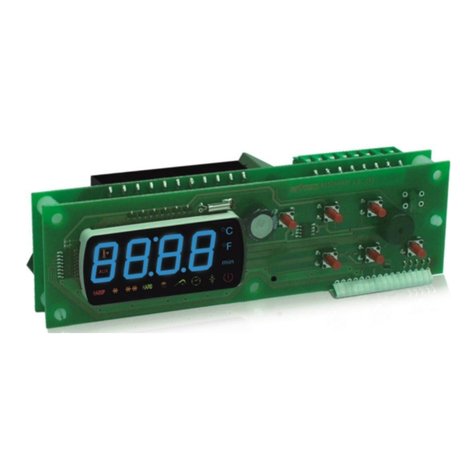
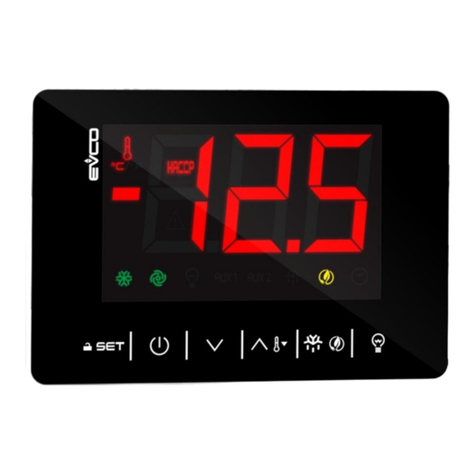
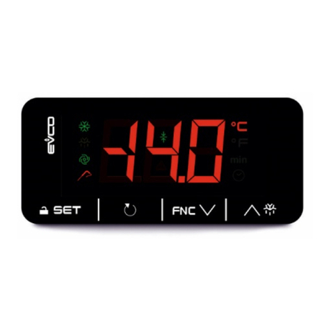
The display has four red-coloured digits (plus decimal points) and 16 icons of various colours; the keypad has 4
keys.
C-PRO NANO

C-PRO NANO HARDWARE MANUAL
Page 5
2Component and auxiliary network systems

C-PRO NANO HARDWARE MANUAL
Page 6
3Technical characteristics
3.1 Connections
Power supply:
The C-PRO NANO is powered by a 12 V AC supply. It may also be powered by a 12 V DC supply; in this
case, there is no option for controlling the fan cut-off modules. The maximum length of the power supply
connecting cables is 1 m.
Analogue input connections:
The C-PRO NANO has two analogue inputs for NTC probes and two for NTC probes or for 0/4-20 mA or 0-5V
ratiometric transducers. Selection is made by the UNI-PRO development system. The current transducers may
be supplied by means of the 12 V DC terminal (refer to the physical layout) with a non-stabilised voltage equal
to 12 V DC. The maximum length of the analogue input connecting cables is 3 m.
Digital input connections:
The C-PRO NANO has 5 non-optoisolated digital inputs (clean contact). The maximum length of the digital
input connecting cables is 3 m.
Digital output connections:
The C-PRO NANO has up to 6 electromechanical relay digital outputs. The maximum length of the digital
output connecting cables is 3 m.
Analogue output connections:
The C-PRO NANO has 1 pulse modulation analogue output to drive the cut phase modules. The maximum
length of this analogue output connecting cables is 1 m.
The C-PRO NANO has 2 voltage or current (optional) analogue outputs. The maximum length of these
analogue outputs connecting cables is 3 m.
Remote terminal connections (IntraBus):
The connection between the C-PRO NANO and the terminal is made using a 3 way cable. The maximum
length of the terminal connection cables is 1 m if using a DC supply from the controller; 30 m where the wall-
mounted keypad is supplied using a separate transformer.
Remote expansions connection (IntraBus):
The connection between the C-PRO NANO and the I/O expansion units is made using a 3 way cable. The
maximum length of the remote I/O expansion units connecting cables is 1 m.
User interface connections (CAN):
The connection between C-PRO NANO and the remote user interface is made using a 2 way cable (better if it
is two weaved couples) plus possible ground.
The maximum length of the connection cables to the remote user interface depends of the CAN port baud rate .
- 1.000 m with 20.000 baud
- 500 m with 50.000 baud
- 250 m with 125.000 baud
- 50 m with 500.000 baud.
The CAN port baud rate is settable by parameter.
C-PRO NANO HARDWARE MANUAL
Page 7
Connection with a remote expansion (or an other CAN controller) :
The connection between C-PRO NANO and the remote expansion (or other CAN controller) is made using a 2
way cable (better if weaved) plus possible ground.
The maximum length of the connection cables to the remote controllers or expansions depend on the CAN port
baud rate (see above section “User interface connections”)
C-PRO NANO and the expansion ( or other CAN controller) power supplies has to be electrically
insulated one from the other.
Notes on the electrical connections
- do not use electric or pneumatic screw-wrenches on the terminal board
- if the device has been moved from a cold to a warm environment, condensation may have formed
inside; please wait approx. one hour prior to switching on
- ensure that the voltage, frequency and operational power of the device are compatible with the local
power supply
- disconnect the power prior to proceeding with any kind of maintenance operation
- do not use the device as a safety device
- for repairs and any information relating to the device, contact the Evco dealer network.
Caution
The instructions governing maximum connecting cable lengths imply that a range of precautions are being
observed:
In order to avoid exemption problems, it is good practice to comply with the following instructions:
-Avoid locations with antennae
-Avoid cabling probe inputs and relay outputs together; generally avoid mixing low and high voltage
signals
-Avoid wrapping cabling around power components
In order to avoid safety problems, it is good practice to comply with the following instructions:
-Avoid premises with relative humidity >90%
-Avoid water
-Avoid corrosive environments
- Avoid explosive environments
Special recommendations
Finally, ensure that the operating conditions are within the limits of use described in the technical
characteristics.

C-PRO NANO HARDWARE MANUAL
Page 8
3.2 The C-PRO NANO wiring layout
The C-PRO NANO control unit wiring layout is shown below, with the meanings of the inputs and outputs
given in the tables.
C-PRO NANO wiring diagram
Connector 1: Output relay connection
Conn. Abbrev. Description
C1-1 DO4 Relay No.4, breaker normally open
C1-2 DO3 Relay No.3, breaker normally open
C1-3 COMMON1 Relays No.s 1,2,3,4 - common
C1-4 DO5 Relay No.5, breaker normally open
C1-5 DO2 Relay No.2, breaker normally open
C1-6 DO1 Relay No.1, breaker normally open
C1-7 COMMON1 Relays No.s 1,2,3,4 - common
C1-8 COMMON1 Relays No.s 1,2,3,4 - common
C1-9 COMMON DO5 Relay No.5 - common
C1-10 Not used
C1-11 DO6 Relay No.6, breaker normally open
Connector 2: Connection for the parameter upload/download key and/or output for RS485 module
and/or controller flash download module

C-PRO NANO HARDWARE MANUAL
Page 9
Connector 3: Analogue output connector
Conn. Abbrev. Description (V+I version)
C3-1 AO2 0-10 V DC
C3-2 GND Common analogue output
C3-3 AO3 4-20 mA
Description (I+I version)
C3-1 AO2 4-20 mA
C3-2 GND Common analogue output
C3-3 AO3 4-20 mA
Description (V+V version)
C3-1 AO2 0-10 V DC
C3-2 GND Common analogue output
C3-3 AO3 0-10 V DC
Connector 4: Connector for low voltage signals
Conn. Abbrev. Description
C4-1 12 V AC (Power) Device power supply (12 V AC/DC)
C4-2 5V Ratiometric power supply
C4-3 GND Common analogue and digital inputs
C4-4 GND Common analogue and digital inputs
C4-5 AI4 Analogue input No. 4 (for NTC probes or for 0/4-20 mA or 0-5V
transducers)
C4-6 AI3 Analogue input No. 3 (for NTC probes or for 0/4-20 mA or 0-5V
transducers)
C4-7 AI2 Analogue input No. 2 (for NTC probes)
C4-8 AI1 Analogue input No. 1 (for NTC probes)
C4-9 12 V AC (Power) Device power supply (12 V AC/DC)
C4-10 12 V DC Current transducer and cut-off module power supply (50 mA max.
not protected against short circuits)
C4-11 AO1 Cut-off module impulse output
C4-12 DI5 Digital input No. 5
C4-13 DI4 Digital input No. 4
C4-14 DI3 Digital input No. 3
C4-15 DI2 Digital input No. 2
C4-16 DI1 Digital input No. 1
Connector 5: Connector for remote keypad and I/O expansion unitb(IntraBus)
Conn. Abbrev. Description
C5-1 12 V DC Remote keypad power supply (12 V DC 50 mA max.; not protected
against short circuits)
(Please note: any expansion units must have a local power supply)
C5-2 GND Common
C5-3 DATA Powered serial connection
Connector 5: Connector for remote keypad and I/O expansion unit (CAN)
Conn. Abbrev. Description
C5-1 CAN+ Connector for the serial CAN+ connection
C5-2 GND Ground reference connection
C5-3 CAN- Connector for the serial CAN- Connection

C-PRO NANO HARDWARE MANUAL
Page 10
3.3 C-PRO NANO dimensions/installation
The mechanical dimensions for the C-PRO NANO are given below; the measurements are in mm (in).
For fitting, use the snap-on brackets provided.
Dimension Minimum Typical Maximum
A 71.0 (2.795) 71.0 (2.795) 71.8 (2.826)
B 29.0 (1.141) 29.0 (1.141) 29.8 (1.173)
Recommendations for installation:
-the panel thickness must not exceed 8 mm (0.314 in)
-95.0 (3.740) is the maximum depth with casing 0065300060 correctly inserted (the connector is not
supplied with the device)
-ensure that the operating conditions (operating temperature, humidity, etc.) are within the limits
indicated in the technical data sheets
-do not install the device near to any sources of heat (heating elements, hot air conduits, etc.),
equipment containing powerful magnets (large diffusers, etc.), areas affected by direct sunlight, rain,
humidity, excessive dust, mechanical vibration or shock
-in compliance with safety regulations, the device must be installed correctly, and in such a way as to
protect against any contact with electrical parts; all safety devices must be fixed so that they cannot be
removed without the use of tools.

C-PRO NANO HARDWARE MANUAL
Page 11
3.4 General characteristics
Safety reference standards EN60730-1
Scope of the device A programmable electronic controller for
refrigeration, ventilation and air
conditioning applications
Storage conditions -10T70°C Non-condensing RU<80%
Operational conditions 0T50°C Non-condensing RU<80%
Electric shock protection class Add-on control device; assumes the
classification of the equipment into
which it is integrated
Disconnection type Reduced interruption (relay breakers)
PTI of the insulation materials >=250 V
Case Panel mounted
Action type 1C
Pollution Normal
Software class A
Insulated parts electrical stress period Long
Front panel protection classification IP65
3.5 Technical characteristics
Low voltage signal connections 16 way Mini-Fit
Power connector 12 way Inarca Edge connector
Cable diameter > 0.75 mm
2
; as
altenative, 12 way Sauro Edge connector
Connection for connecting the EVCO powered serial
port to the remote keypad and/or remote I/O expansion
card
JST 3 way P2.5
Connection for parameter key, TTL serial output for
RS485 module, Flash programming interface 6 way AMP micro-match
Connection for D/A output JST 3 way P2.5
16 WAY MINI-FIT CONNECTOR SPECIFICATIONS
SUPPLIER
CONNECTOR CODE
CONTACT CODE
Please note:
use the special tool for crimping
CVILUX
CP-01 116010 (V2)
CP-01 116020 (V0)
CP-01 1000102 (AWG16÷24)
SELECOM
6137R16WO (V2)
6137TR1 (AWG16÷20)
6137TR2 (AWG22÷26)
JUSCOM
1090-557-162 (V2)
1150-156-012 (AWG18÷22)
1150-156-002 (AWG22÷26)
CONEXCON
6740-1161 (V2)
6740-1160 (V0)
6744-2000 (AWG18÷22)
MOLEX
39-01-2160 (V2)
39-01-2165 (V0)
39-00-0038 (AWG18÷24)
39-00-0046 (AWG22÷28)

C-PRO NANO HARDWARE MANUAL
Page 12
3.6 Electrical characteristics
CPU Microcontroller 8 bit
Program flash memory 128 Kbyte
RAM for data memory 4 Kbyte
EEPROM 4 Kbyte
A/D 8 channels at 10 bit
Power supply Voltage 12 V AC/DC
Range -10% +15%
Frequency 50/60 Hz / DC
Maximum input power 6 VA
Fuse rating External
Digital outputs Number 6
Type Electromechanical relays
Maximum breaker current at 250 V AC
Use all common connectors. 2 (1) A for DO1, DO2, DO3
and DO4
3 (1) A for DO5 and DO6
Number of processing cycles 100,000
Minimum switching interval 20 s
Micro-switch action type 1C
Insulation between relays and low
voltage Reinforced
Insulation between relays Functional
Insulation between relays and DO6 Reinforced
Digital inputs Number 5
Type Clean contact
Breaker closure current to earth 2 mA
Maximum closure resistance 100 Ω
OFF to ON detection time 100 ms
ON to OFF detection time 100 ms
Analogue inputs for Number 2
NTC probes Type NTC (10 KΩ±1% @25°C)
NTC measurement range -40°C ÷100°C
NTC measurement accuracy ±1°C
NTC measurement sensitivity 0.1°C
Analogue inputs for Number 2
NTC probes or Type NTC (10 KΩ±1% @25°C)
Ratiometric pressure NTC measurement range -40°C ÷100°C
Transducers NTC measurement accuracy ±1°C
NTC measurement sensitivity 0.1°C
Type Current
Current measurement range 0/4 ÷20 mA
Current measurement accuracy ±0.08 mA
Current measurement sensitivity 0.01 mA
Input resistance
Type
Voltage measurement range
Voltage measurements accuracy
Voltage measurement sensitivity
200 Ohm
Ratiometric
0 ÷5V
±50 mV
10 mV

C-PRO NANO HARDWARE MANUAL
Page 13
Fan analogue output Number 1
Type EVCO impulse cut-off
UART1 TTL Number 1
for RS485 serial port Type UART
(Modbus) Physical layer TTL level signals
Maximum baud rate 19200 bit/s
Connector 6 way AMP micro-match
Please note: The same connector for
the serial port is used for the
parameter key and for the interface
used for programming the
microcontroller flash memory
Serial output for remote Number 1
I/O expansion unit Type EVCO powered serial port
and remote keypad Physical layer 12 V DC, GND, DATA
Baud rate 19200 bit/s
Connector sconn. JST 3 way P2.5
Analogue output Number 1+1
Voltage + Current, Connector sconn. JST 3 way P2.5
Voltage + Voltage or Power supply Internal (non optoisolated)
Current + Current Type Current
Current range 4 ÷20 mA
Current output accuracy ±0.4 mA
Current output sensitivity 0.01 mA
Current output load 47 ÷300 Ω
Adjustment time 1 s
Type Voltage
Voltage range 0 ÷10 V
Voltage output accuracy ±200 mV (unloaded)
Voltage output sensitivity 10 mV
Output impedance 100 Ω
Adjustment time 1 s
CAN communication
Bus Number 1
type CAN V2.0B no optoinsulated
Physical layer 2 wires + common wire
(ISO 11898)
Baud rate (max. length = 1000 m) 20K
Baud rate (max. length = 500 m) 50K
Baud rate (max. length = 250 m) 125K
Baud rate (max. length = 50 m) 500K
Connector Disconnectable screw terminals
Note:
1) baud rate selectable by parameters
2)
The CAN connection consists of a cable with twisted pair (both shielded and
not shielded). The first and the last elements of the system must have the bus
terminating resistor connected (impedance is 120
Ω
).

C-PRO NANO HARDWARE MANUAL
Page 14
4The C-PRO NANO user interface
The display has four red-coloured digits (plus decimal points) and 16 icons of various colours; the keypad has 4
keys.
C-PRO NANO
Display Number of digits 4
Colour Red
Summer icon (air conditioning display)
Circuit 1 icon (refrigeration display) Colour Green
Winter icon (air conditioning display)
Circuit 2 icon (refrigeration display) Colour Green
Fan icon (air conditioning display)
High pressure circuit icon (refrigeration display) Colour Green
Pump icon (air conditioning display)
Low pressure circuit icon (refrigeration display) Colour Green
EVCO icon Colour Amber
Defrost icon (air conditioning display)
Fan icon (refrigeration display) Colour Amber
°F icon (air conditioning display)
Bar icon (refrigeration display) Colour Red
°C icon Colour Red

C-PRO NANO HARDWARE MANUAL
Page 15
Maintenance icon Colour Red
Alarm icon Colour Red
Icon 1 Colour Green
Icon 2 Colour Green
Icon 3 Colour Green
Icon 4 Colour Green
Heating element icon (air conditioning display)
Compressor icon (refrigeration display) Colour Green
On-Off icon Colour Red
Keys Number of keys 4
Set / enter key Normal pressing ENTER (confirms the value/runs the
command)
Pressed for approx. 3
seconds Accesses programming parameters
OnOff/esc key Normal pressing ESC (cancels the value/returns to the
previous menu)
Pressed for approx. 3
seconds Powers the unit on/off
Up key Normal pressing UP
Secondary function Programmable
Down key Normal pressing DOWN
Secondary function Programmable
Esc+enter keys Pressed for approx. 3
seconds Accesses the second level programming
parameters
Up+down key Pressed for approx. 3
seconds Displays device/firmware version, revision
information

C-PRO NANO HARDWARE MANUAL
Page 16
5C-PRO EXP MICRO I/O expansion units
The C-PRO EXP MICRO I/O expansion units allow expansion of the controllers I/O capacity. There are two
types of expansion unit, one sealed in a case with 4 DIN modules, and another open mounted on a base with 4
DIN modules.
C-PRO EXP MICRO
Sealed case version with 4 DIN
modules
C-PRO EXP MICRO
Open version mounted on a base
with 4 DIN modules

C-PRO NANO HARDWARE MANUAL
Page 17
5.1 The C-PRO EXP MICRO wiring layout (IntraBus version)
The references to connecting cable lengths reported in chapter 3 are also valid for I/O expansion units.
The C-PRO EXP MICRO expansion unit wiring layout is shown below, with the meanings of the inputs and
outputs given in the tables.
C-PRO EXP MICRO wiring diagram
The C-PRO NANO and C-PRO EXP MICRO power supplies must be galvanically isolated
from one another.
Connector 1: Output relay connection
Conn. Abbrev. Description
C1-1 DO1 Relay No.1, breaker normally open
C1-2 COMMON DO1 Relay No.1 - common
C1-3 DO2 Relay No.2, breaker normally open
C1-4 COMMON DO2 Relay No.2 – common
C1-5 DO3 Relay No.3, breaker normally open
C1-6 COMMON DO3 Relay No.3 - common
C1-7 DO4 Relay No.4, breaker normally open
C1-8 COMMON DO4, DO5 Relay No.s 4, 5 - common
C1-9 DO5 Relay No.5, breaker normally open
C1-11 DO6 Relay No.6, breaker normally open

C-PRO NANO HARDWARE MANUAL
Page 18
C1-12 COMMON DO6 Relay No.6 - common
Connector 2: Connector for low voltage signals
Conn. Abbrev. Description
C2-1 12 V AC (Power) Device power supply (12 V AC/DC)
C2-2 Not connected Not connected
C2-3 GND Common analogue and digital inputs
C2-4 GND Common analogue and digital inputs
C2-5 AI4 Analogue input No. 4 (for NTC probes or for 0/4-20 mA or 0-5V
transducers)
C2-6 AI3 Analogue input No. 3 (for NTC probes or for 0/4-20 mA or 0-5V
transducers)
C2-7 AI2 Analogue input No. 2 (for NTC probes)
C2-8 AI1 Analogue input No. 1 (for NTC probes)
C2-9 12 V AC (Power) Device power supply (12 V AC/DC)
C2-10 12 V DC Current transducer and cut-off module power supply (50 mA max.
not protected against short circuits)
C2-11 AO1 Cut-off module impulse output
C2-12 DI5 Digital input No. 5
C2-13 DI4 Digital input No. 4
C2-14 DI3 Digital input No. 3
C2-15 DI2 Digital input No. 2
C2-16 DI1 Digital input No. 1
Connector 3: Connector to the controller (IntraBus)
Conn. Abbrev. Description
C3-1 VDC Power supply
C3-2 GND Common
C3-3 DATA Powered serial connection
Connector 3: Connector to the controller (CAN)
Conn. Abbrev. Description
C3-1 + Connector for the serial CAN + connection
C3-2 GND Ground reference connector
C3-3 - Connector for the serial CAN - connection

C-PRO NANO HARDWARE MANUAL
Page 19
5.2 C-PRO EXP MICRO dimensions/installation
The mechanical dimensions for the C-PRO EXP MICRO are given below; the measurements are in mm (in).
6Accessories
6.1 User terminals (IntraBus)
User terminals allow the control units to be controlled remotely (display and commands). There are two
interface types, one panel-mounted, the other wall-mounted. The interface is connected to the special (powered)
serial connector of the C-PRO NANO controllers.
V LEDi
Panel-mounted version
V WALL
Wall-mounted version

C-PRO NANO HARDWARE MANUAL
Page 20
6.1.1 V LEDi dimensions and installation
For panel installation, use the snap-on brackets provided
Local panel interface dimensions
Connections
DATA
GND
123
12Vdc
CI1
Local panel interface connections
Connector CI1: Interface connector
Conn. Abbrev. Description
CI1-1 12 V DC Keypad power supply
CI1-2 GND Common
CI1-3 DATA EVCO powered serial port
C-PRO NANO with V LEDi wiring diagram
Other manuals for C-PRO NANO
1
Table of contents
Other Evco Controllers manuals

Evco
Evco EVJ 700 User guide

Evco
Evco EVD MVC Series User manual

Evco
Evco c-pro 3 nano CHIL Instructions for use

Evco
Evco c-pro 3 OEM User manual

Evco
Evco c-pro 3 micro AHU User manual

Evco
Evco EV3S204 User manual

Evco
Evco EVK614 User manual

Evco
Evco EVBOX Light JS200 User manual

Evco
Evco EV3B33N7VXRX04 User manual

Evco
Evco c-pro 3 nano CHILL User manual

Evco
Evco Vcolor 279 Instructions for use

Evco
Evco EV3 WEB User guide

Evco
Evco EVJ254 User manual

Evco
Evco EVBOX Light J500 Series User manual

Evco
Evco EVXS214 User manual

Evco
Evco EVJ 200 User manual

Evco
Evco Vcolor 679 User guide

Evco
Evco EV3221 User manual

Evco
Evco EC 6-295 User manual

Evco
Evco EVK004 User manual