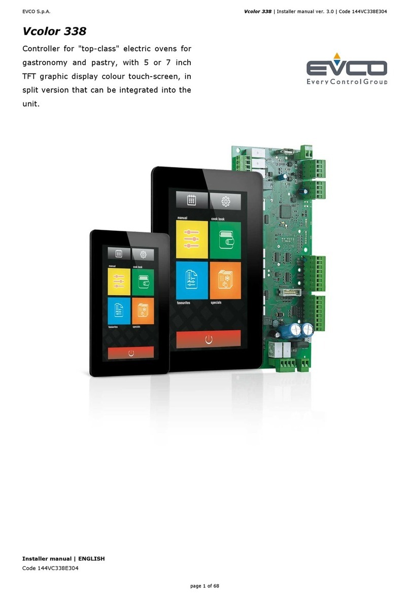
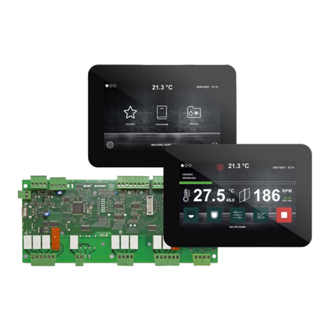
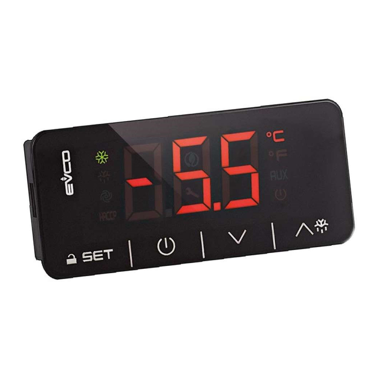
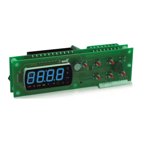
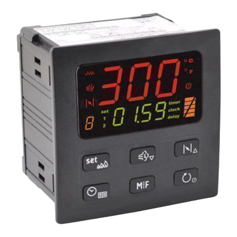
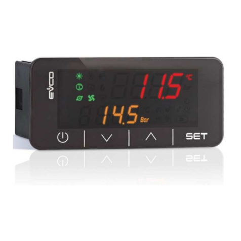
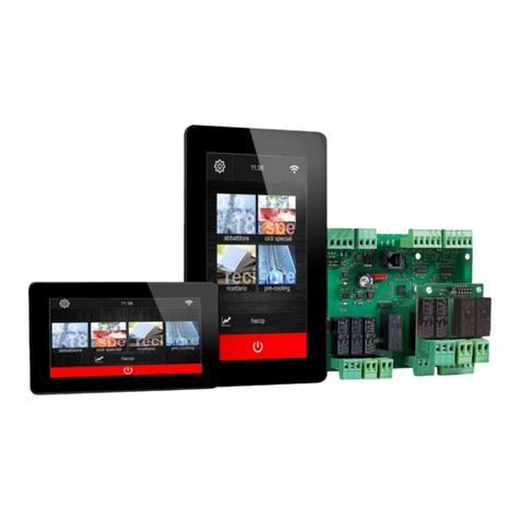
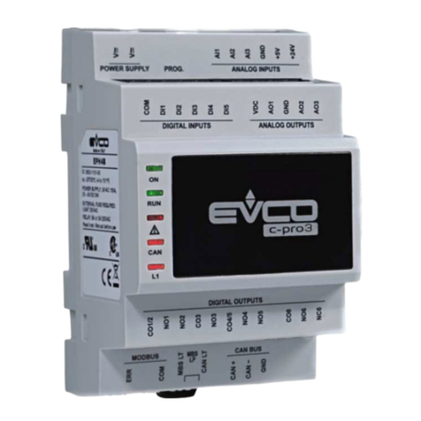
Evco c-pro 3 micro CHIL Series Instructions for use

EVCO S.p.A.
c-pro 3 micro CHIL | Application manual ver. 1.0 | Codice 144CP3CHE104
c-pro 3 micro CHIL
Programmable controller for ingle-and
two-circuit chiller -heat pump
Application manual | ENGLISH
Codice 144CP3CHE104

EVCO S.p.A.
c-pro 3 micro CHIL | Application manual ver. 1.0 | Codice 144CP3CHE104
page 2 of 120
IMPORTANT NOTICE
Thi In truction Manual hould be read carefully before in tallation and before u e, and all warning relating
to in tallation and electrical connection hould be ob erved; the Manual hould then be kept for future
reference.
All devices must be disposed o in accordance with local regulations governing the disposal o
electrical and electronic devices.

EVCO S.p.A.
c-pro 3 micro CHIL | Application manual ver. 1.0 | Codice 144CP3CHE104
page 3 of 120
SOMMARIO
1
INTRODUCTION ................................................................................................... 6
1.1
Introduction ..................................................................................................... 6
2
APPLICATIONS .................................................................................................... 7
2.1
Basic application scheme o an Air-To-Water twin circuit chiller ...................... 8
3
HARDWARE SOLUTIONS ...................................................................................... 9
4
DIMENSIONS ..................................................................................................... 10
4.1 Dimensions o controller and user inter ace ....................................................... 10
4.1.1 Dimensionscontrol modulec-pro 3microCHILand c-pro 3 EXP micro+ ............................................................. 10
5
USER INTERFACE ............................................................................................... 12
5.1
Displays and Keyboards.................................................................................. 12
6
LIST OF PAGES ................................................................................................... 13
6.1
Password ........................................................................................................ 14
6.2
Unit OFF main page ........................................................................................ 14
6.3
Unit ON main page ......................................................................................... 15
6.4
Menu StAt (Only or display LED) ................................................................... 16
6.4.1
Meaning o LED (only or display LED) .................................................................................................. 17
6.5
General Menu ................................................................................................. 18
6.6
User Menu ...................................................................................................... 18
6.7
Maintenance Menu .......................................................................................... 18
6.8
Installer Menu ................................................................................................ 19
6.9
Constructor Menu ........................................................................................... 20
6.10
RTC Menu .................................................................................................... 20
6.11
Alarms Menu ............................................................................................... 20
7
PARAMETERS LIST ............................................................................................. 21
7.1
List o Con iguration Parameters .................................................................... 22
7.2
AI Con iguration (HA01-HA18 parameters) .................................................... 41
7.3
DI Con iguration(HB01-HB18 parameters) ..................................................... 42
7.4
AO Con iguration (HC01-HC18 parameters) ................................................... 42
7.5
DO Con iguration (HD01-HD18 parameters)................................................... 43
8
REGULATIONS.................................................................................................... 44
8.1
Machine Status ............................................................................................... 44
8.2
Unit Type ........................................................................................................ 45
8.2.1
Water-To-Water Chiller with EVDRIVE03 .............................................................................................. 45
8.2.2
Water-To-Water Chiller ......................................................................................................................... 46
8.2.3
Water-To-Water Chiller+Heat Pump with EVDRIVE03 ........................................................................... 47
8.2.4
Water-To-Water Chiller+Heat Pump ..................................................................................................... 48
8.2.5
Air-To-Water Chiller with EVDRIVE03 ................................................................................................... 49
8.2.6
Air-To-Water Chiller .............................................................................................................................. 50
8.2.7
Air-To-Water Chiller+Heat Pump with EVDRIVE03 ................................................................................ 51
8.2.8
Air-To-Water Chiller+Heat Pump .......................................................................................................... 52

EVCO S.p.A.
c-pro 3 micro CHIL | Application manual ver. 1.0 | Codice 144CP3CHE104
page 4 of 120
8.3
Con iguration o Circuits ................................................................................. 53
8.4
Operating Mode Control .................................................................................. 54
8.5
Setting the RTC .............................................................................................. 55
8.6
Compressor Control ........................................................................................ 56
8.6.1
Lateral-band (LB) control ...................................................................................................................... 56
8.6.2
Zero energy band (ZEB) control ............................................................................................................ 57
8.6.3
Auto adaptive control ........................................................................................................................... 58
8.7
Compressor Management ............................................................................... 58
8.7.1
Compressor status ................................................................................................................................ 58
8.7.2
Rotation o compressors ....................................................................................................................... 58
8.7.3
Pump-down switch-OFF procedure ....................................................................................................... 59
8.7.4
Relative-threshold pump-down ............................................................................................................. 59
8.7.5
Protection timings ................................................................................................................................. 60
8.7.6
Thermal protection inputs ..................................................................................................................... 61
8.8
Condenser control .......................................................................................... 61
8.8.1
Modulating an control .......................................................................................................................... 61
8.8.2
Single stage an control ........................................................................................................................ 64
8.8.3
Condenser valve control ........................................................................................................................ 64
8.8.4
Single condenser ................................................................................................................................... 64
8.9
Fan Management ............................................................................................ 65
8.9.1
Fan status ............................................................................................................................................. 65
8.9.2
Fan timings ........................................................................................................................................... 65
8.9.3
Thermal Protection Inputs .................................................................................................................... 65
8.10
Circulating Pump Management .................................................................... 66
8.10.1
Pump Status .......................................................................................................................................... 67
8.10.2
Flow Meter Management ....................................................................................................................... 67
8.11
Circulating Source Pump Management ........................................................ 68
8.12
De rosting Management .............................................................................. 68
8.12.1
De rosting cycle compensation ............................................................................................................. 69
8.13
Anti- reeze management / Chilling-support heating coils ........................... 69
8.14
Single evaporation ...................................................................................... 69
8.15
Free-Cooling Management........................................................................... 70
8.15.1
Enabling o Free-Cooling ....................................................................................................................... 70
8.15.2
Regulation o Free-Cooling .................................................................................................................... 70
8.15.3
Free-Cooling control valve .................................................................................................................... 72
8.16
Temperature Alarm Control ......................................................................... 73
8.16.1
Low and high temperature alarm management ..................................................................................... 73
8.16.2
Management o primary exchanger e iciency alarm ............................................................................. 73
8.17
Pressure Alarm Control ............................................................................... 73
8.17.1
Management o high-pressure pressure-switch alarm .......................................................................... 73
8.17.2
Management o high-pressure transducer alarm ................................................................................... 73
8.17.3
Management o low-pressure pressure-switch alarm (chiller mode) .................................................... 73
8.17.4
Management o low-pressure transducer alarm (heat pump mode) ...................................................... 74
8.17.5
Low start-up pressure alarm ................................................................................................................. 74
8.18
Time schedule ............................................................................................. 75
8.19
Miscellaneous Management ......................................................................... 76
8.19.1
Set point variation by schedule timer .................................................................................................... 76
8.19.2
Dynamic set point ................................................................................................................................. 76

EVCO S.p.A.
c-pro 3 micro CHIL | Application manual ver. 1.0 | Codice 144CP3CHE104
page 5 of 120
8.19.3
Forced shutdown ................................................................................................................................... 77
8.19.4
High-pressure reduction at high temperatures (chiller) ........................................................................ 77
8.19.5
Low-pressure partialization at low temperatures (heat pump) ............................................................. 78
8.19.6
Operating limit management (heat pump) ............................................................................................ 79
8.19.7
Function o Cooling/Heatingupon request ............................................................................................. 79
8.19.8
Set-point change rom digital input ....................................................................................................... 79
8.20
Management o EVDRIVE03 integrated into the system .............................. 80
8.20.1
Enabling o EEV operation ..................................................................................................................... 80
8.20.2
PID parameters set ............................................................................................................................... 80
8.20.3
Modulation o the SH set ....................................................................................................................... 80
8.20.4
CAN Con iguration ................................................................................................................................. 80
8.21
Manual operation ........................................................................................ 81
8.21.1
Compressors ......................................................................................................................................... 81
8.21.2
Fans ...................................................................................................................................................... 81
8.21.3
Pumps ................................................................................................................................................... 81
8.22
Resetting o de ault parameters .................................................................. 82
8.23
Parametering key ........................................................................................ 82
9
WIRING DIAGRAM ............................................................................................. 83
9.1 Connection layout c-pro 3 micro CHIL ................................................................ 83
9.2 Connection layout c-pro 3 EXP micro+ ............................................................... 85
9.3 Connection layout EVDRIVE03 ............................................................................ 87
9.4 Connection layout Vgraph ................................................................................... 89
9.5 c-pro 3 micro CHIL ............................................................................................ 90
10
9.5.1 Table o connection c-pro 3 micro CHIL .................................................... 91
11
DIAGNOSTICS .................................................................................................... 92
11.1
Manual and Automatic Alarms ..................................................................... 92
11.2
Manual-reset alarms ................................................................................... 92
11.3
Automatic-reset alarms ............................................................................... 92
11.4
Alarm Table ................................................................................................. 93
11.5
Alarms History ............................................................................................ 96
12
LIST OF Modbus® VARIABLES ........................................................................... 97

EVCO S.p.A.
c-pro 3 micro CHIL | Application manual ver. 1.0 | Codice 144CP3CHE104
page 6 of 120
1INTRODUCTION
1.1 Introduction
The programmable controller of the c-pro 3 micro CHIL erie are device tudied for the management of ingleandtwo-circuit
chiller -heat pump up to three crollcompre or for each circuit.
They make u e of the programmable controller , of the I/Oexpan ion and of the remote u er interface belonging tothe c-pro 3 erie
and are programmed with an application oftware implemented with the development environmentUNI-PRO 3.
They are available in built-in and in blind ver ion; the blindver ion mu t be u ed with a remote u er interface.
The controller can manage air to water and water to waterchiller -heat pump ; through the CAN communication portthe controller
can al o communicate with an externaldriver (EVDRIVE03) for bipolar tepper electronic expan ionvalve .
They can be powered in alternating current (12 VAC). Through the programming port it i po ible to make the upload and the
download of the configuration parameter (u ing a common USB peripheral); through the RS-485 one, with MODBUS communication
protocol, it i po ible to connect the device to the et-up oftware y tem Parameter Manager or to the plant monitoring and
upervi ion one via Internet CloudEvolution in tead. Through the CAN communication port it i finally po ible to connect the device to
the I/O expan ion, to the remote u er interface and to the external electronic expan ion valve driver.
The application program i capable of managing air-to-water and water-to-water unit , mono or twin circuit.
The following are only ome of the numerou control function available:
Available unctions
Manage up to 3 croll compre or for each circuit
Manage compre or with cooling – heating mode
Manage fan with pha e-cut module
Manage electronic valve EVDRIVE03 for each circuit
Free-Cooling management
Defro t and anti-fro t
Double et-point that can be enabled from external contact
Dynamic et point compen ation
Pump-down management
Build in chedule with 2 daily program
Control of conden ing pre ure / linear or tepped evaporation
One, two or no circulating pump
One, two or no ource circulating pump

EVCO S.p.A.
c-pro 3 micro CHIL | Application manual ver. 1.0 | Codice 144CP3CHE104
page 7 of 120
2APPLICATIONS
The controller are able to manage the following unit type :
Air-To-Water single circuit
Air-To-Water ingle circuit Chiller
Air-To-Water ingle circuit Chiller with EEV driver
Air-To-Water ingle circuit Chiller + HeatPump
Air-To-Water ingle circuit Chiller + HeatPump with EEV driver
Water-To-Water single circuit
Water-To-Water ingle circuit Chiller
Water-To-Water ingle circuit Chiller with EEV driver
Water-To-Water ingle circuit Chiller + HeatPump
Water-To-Water ingle circuit Chiller + HeatPump with EEV driver
Air-To-Water twin circuit
Air-To-Water twin circuit Chiller
Air-To-Water twin circuit Chiller with EEV driver
Air-To-Water twin circuit Chiller + HeatPump
Air-To-Water twin circuit Chiller + HeatPump with EEV driver
Water-To-Water twin circuit
Water-To-Water twin circuit Chiller
Water-To-Water twin circuit Chiller with EEV driver
Water-To-Water twin circuit Chiller + HeatPump
Water-To-Water twin circuit Chiller + HeatPump with EEV driver

EVCO S.p.A.
c-pro 3 micro CHIL | Application manual ver. 1.0 | Codice 144CP3CHE104
page 8 of 120
2.1 Basic application scheme o an Air-To-Water twin circuit chiller

EVCO S.p.A.
c-pro 3 micro CHIL | Application manual ver. 1.0 | Codice 144CP3CHE104
page 9 of 120
3HARDWARE SOLUTIONS
Hardware Article Code
Controller (built-in ver ion) c-pro 3micro CHIL EPU2LXP1CH
Controiller (blind ver ion) c-pro 3micro CHIL EPU2BXP1CH
I/O expan ion c-pro 3 EXP micro+ EPU2EXP
EEV driver (built-in ver ion) EVDRIVE03 EPD4DF3
EEV driver (blind ver ion) EVDRIVE03 EPD4BC3
To manage the econd circuit it i nece ary to u e an I/O expan ion c-proEXP micro+ and to manage the electronic expan ion valve it
i nece ary to u e a driver EVDRIVE03.
For management of the blind ver ion it i al o nece ary to u e a remote u er interface LCDVgraph, an interfaceequipped with
6key /edit page , tate and enablingthe ame.
A de criptionof the key u ed by the application.

EVCO S.p.A.
c-pro 3 micro CHIL | Application manual ver. 1.0 | Codice 144CP3CHE104
page 10 of 120
4DIMENSIONS
4.1 Dimensions o controller and user inter ace
Below we will how the dimen ion , a embly and electric connection of the c-pro 3 micro CHIL.
4.1.1 Dimensionscontrol modulec-pro 3microCHILand c-pro 3 EXP micro+
4 DIN module , in tallation DIN rail mounting; the dimen ion arein mm(in).
4.1.2 Dimensions remote user inter ace Vgraph.
In tallation by panel; the dimen ion are in mm (in).

EVCO S.p.A.
c-pro 3 micro CHIL | Application manual ver. 1.0 | Codice 144CP3CHE104
page 11 of 120
4.1.3 Dimensions module EVDRIVE03
4 DIN module , in tallation DIN rail mounting; the dimen ion arein mm(in).

EVCO S.p.A.
c-pro 3 micro CHIL | Application manual ver. 1.0 | Codice 144CP3CHE104
page 12 of 120
5USER INTERFACE
For the application, two type of interface are provided:
•Built-in LED-di play interface
•Remote LCD-di play interface Vgraph.
Both interface feature 6 key for navigation/page editing, and differ in their di play mode of certain a ociated tatu e , i.e. via icon .
For both ver ion , a de cription i provided of the key u ed by the application; indeed, according to the interface in u e, it i po ible
to manage a different number of key .
5.1 Displays and Keyboards
The keyboard feature 6 page navigation and value editing key , which have the following function :
Symbol
Functions
In editing, it modifie parameter ; otherwi e, it move the cur or.
During editing, it confirm the value; otherwi e, it end any command a ociated to the text where the
cur or i po itioned.If pre ed down and held for about 2 econd , the ENTER key enable acce to the main menu.
If held down during di play of an alarm page, thi key enable re etting of the alarm.If alarm page are being
di played, every key pre croll all active alarm .
During editing, it cancel the value; otherwi e, it reque t any default page that might e a ociated with the current
page.If pre ed down and held for about 2 econd , the ESC key enable ON/OFF witching of the machine.
If pre ed in the main page, thi key will di play the li t of all active alarm .
It di play the page of the ame level in ucce ion.

EVCO S.p.A.
c-pro 3 micro CHIL | Application manual ver. 1.0 | Codice 144CP3CHE104
page 13 of 120
6LIST OF PAGES
Thi chapter de cribe the main page and menu featured in the application. A already de cribed earlier, the general menu i
ubdivided into four ubmenu level : u er, maintenance operator, in tallation operator, and configuration.
The menu tructure i the following:
Menu
Function o the menu
General Menu
RTC Menu
Alarm Menu
U er Menu (Level 1)
Maintenance Menu
(Level 2)
Operation
Manual
Calibration
Input/output
Installer Menu
(Level 3)
Compre or
Regulation
Fan
Defro t
Pump
Anti-Freeze
Free-Cooling
Device afetie
Modbu
Variou parameter
Constructor Menu
(Level 4)
Configuration
Hardware configuration
EVDRIVE03 (Circuit 1, Circuit 2)

EVCO S.p.A.
c-pro 3 micro CHIL | Application manual ver. 1.0 | Codice 144CP3CHE104
page 14 of 120
6.1 Password
Each menu i a igned a level, which affect the acce ibility of the variou menu .
Each level i a igned a pa word, which enable acce to the variou function featured in that menu; once the correct pa word ha
been entered, protected function become acce ible. Entering of the correct pa word ha two con equence :
•Unlocking of the related level;
•Unlocking of it ublevel .
All level pa word can be modified from the ame level or from higher level . For example, from the con tructor level it will be po ible
to modify all pa word of underlying level , by u ing the appropriate page.
The range of value that can be et for a pa word i -999 / 9999.
After 4 minute have elap ed without any key being pre ed, the pa word expire and it i nece ary to re et it.
6.2 Unit OFF main page
The main di play page varie according to the machine tatu , i.e. on or off:If the machine i witched OFF, Unit OFF i di played, with
indication of the cau e for the hutdown (keyboard, DI, Supervi or, Scheduler, Alarm, Change-Over).
Pre ing the ESC key from thi page bring the u er to the Alarm page.

EVCO S.p.A.
c-pro 3 micro CHIL | Application manual ver. 1.0 | Codice 144CP3CHE104
page 15 of 120
6.3 Unit ON main page
When the unit i turned on, the following main creen will be di played:
At the bottom of the page, icon will be di played that indicate variou tatu e of circuit operation.
The table below contain graphic repre entation of the individual icon , the relative operational tatu and what i being verified.
From left to right:
Icon
Operational status
Eventdisplayed
Summer/Winter/Alarm Icon In ca e there i an active alarm, the alarm icon will be di played alternatively with
the icon of the operational mode ( ummer/winter)
Defro t Icon Indicate that circuit defro t i in progre (1,2).
If fla hing, it i in dripping pha e
Antifreeze Icon Indicate that the antifreeze re i tance mechani m i active (heat ink or ource)
in the circuit indicated (1,2 1+2)
Fan Icon Indicate that the circuit fan (1,2, 1+2) are active
Pump Icon Indicate which circulation pump (1,2) i active
Compre or Icon Indicate that at lea t one circuit compre or (1,2, 1+2) i active
Time Slot Icon Indicate which time lot i active (A,B)
From thi page, by pre ing the RIGHT or LEFT key , it i po ible to di play other information regarding pump , fan , compre or ,
defro t, circuit tatu , RTC and all configured en or . In ca e of fault tatu of the en or , the value field of the corre ponding en or
di play “----“, or el e “----“ if the en or i di abled.
Pre ing the ESC key from thi page bring the u er to the Alarm page.

EVCO S.p.A.
c-pro 3 micro CHIL | Application manual ver. 1.0 | Codice 144CP3CHE104
page 16 of 120
6.4 Menu StAt (Only or display LED)
If the StAt voice i cho en from the general menu, everal main tatu e of the y tem are di played (can be navigatedwith the
Left/Right button ) on the reference page:
Exampletable of y tem tatu e di played on Page 1
Re erence page Status displayed System status
Page 1 Unit Indicate the tatu in which the machine operate (OFF, ChIL, pdC, dEFr, dRIp, F-C)
Page 1 ModE Indicate the operational mode of the machine (ChIL, pdC)
Page 1 tdF1 Accumulation of wait time for defro t circuit 1
Page 1 dFr1 Duration of circuit defro t 1
Page 1 tdF2 Accumulation of wait time for defro t circuit 2
Page 1 dFr2 Duration of defro tcircuit 2
Page 1 SEtC Summer mode current et point
Page 1 SEtH Winter mode current et point
Page 1 rEGP Main regulation probe
Page 1 PREq Power required [%]
Page 1 PSup Power upplied[%]
Example table of y tem tatu e di played on Page 2
Re erence page Status displayed System status
Page 2 CMP1, CMP2 .. CMP6 Statu of compre or (dIS, OFF, tOn, On, tOFF, ALAr, MAnU)
Page 2
FAn1, FAn 2 Statu of fan (dIS, OFF, tOn, On, tOFF, ALAr, MAnU)
Page 2
InF1,InF2 Speed of conden er fan [%]
Page 2
PMP1, PMP2 Statu of pump (dIS, OFF, On, ALAr, MAnU)
Page 2
PMS1, PMS2 Statu of heat ource pump (dIS, OFF, On, ALAr, MAnU)
Page 2
F-C Statu of free-cooling activation
Page 2
vF-C Free-cooling valve
Page 2
FF-C Free-cooling regulation
Page 2
vpC1 Statu of C1 plitter valve for free-cooling
Page 2
vpC2 Statu of C2 plitter valve for free-cooling
Sample table of y tem tatu e di played on Page 3
Re erence page Status displayed System status
Page 3 tExt External temperature probe
Page 3
tAux Remote temperature probe
Page 3
tiFc Machine input temperature probe (Free-Cooling)
Page 3
tin Heat ink exchanger input temperature probe
Page 3
toC1/2 Heat ink exchanger output temperature probe (circuit 1,2)
Page 3
toS1/2 Heat ource exchanger input temperature probe (circuit 1,2)
Page 3
tCo1/2 Coil temperature probe (circuit 1,2)
Page 3
GAS1/2 Exhau t ga compre or temperature probe (circuit 1,2)
Page 3
tSu1/2 Intake compre or temperature probe (circuit 1,2)
Page 3
PCO1/2 Conden ing pre ure probe (circuit 1,2)
Page 3
PEV1/2 Evaporation pre ure probe (circuit 1,2)
Page 3
Pun1/2 Single pre ure probe (circuit 1,2)

EVCO S.p.A.
c-pro 3 micro CHIL | Application manual ver. 1.0 | Codice 144CP3CHE104
page 17 of 120
Pre ing ENTER on the label cau e the value of the relative tatu to be di played;pre ing ESC bring you back to the general menu
creen. Thi menu i not protected by a pa word.
6.4.1 Meaning o LED (only or display LED)
The LED di play offer everal icon that di play particular tatu e of the unit:
•OnO . If on, it mean that the unit ha no power; if off, it mean that the unit i on; if on with low fla hing light, it mean
that the unit i not being powered by the Scheduler; if on with fa t fla hing light, it mean that the unit i not being powered
by the Supervi or or Digital Input.
•Snow. If on, ummer/winter function ( eeparameter PH53); if on and fla hing, the free-cooling function i active.
•Sun. If on, ummer/winter function ( ee parameter PH53).
•Alarm. If on, the function indicate the pre ence of alarm ; if on and fla hing, it indicate the pre ence of new alarm not
di played yet; if off, there are no alarm .
•De rost. If on, it mean that defro ting i active in one of the 2 circuit ; if on and fla hing, it mean that draining i active in
one of the2 circuit
•Maintain. If on, it mean that at lea t one device i functioning manually; if on and fla hing, it mean that a “device
operating hour ” alarm i active.
•Compressor 1. If on, it mean that at lea t one compre or of circuit 1 i active; if off, it mean that no circuit compre or
are active; if on and fla hing lowly, it mean that a circuit compre or i in the alarm tate; if on and fla hing quickly, it
mean that a circuit compre or i in manual mode.
•Compressor 2. If on, it mean that at lea t one compre or of circuit 2 i active; if off, it mean that no circuit compre or
are active; if on and fla hing lowly, it mean that a circuit compre or i in the alarm tate; if on and fla hing quickly, it
mean that a circuit compre or i in manual mode.
•Pump. If on, it mean that a heat ink pump i active; if off, it mean that no pump are active; if on and fla hing lowly, it
mean that a pump i in the alarm tate; if on and fla hing quickly, it mean that a pump i in manual mode.
•Fan. If on, it mean that one fan i active; if off, it mean that no fan are active; if on and fla hing lowly, it mean that a
fan i in the alarm tate; if on and fla hing quickly, it mean that a fan i in manual mode.
•Heaters: If on, it mean that the trength of the antifreeze mechani m (heat ink or ource) i active; if off, it mean that no
antifreeze mechani m are active; if on and fla hing lowly, it mean that an antifreeze mechani m i in the alarm tate.
•EVCO. Icon linked to the functioning of parameter PH52.

EVCO S.p.A.
c-pro 3 micro CHIL | Application manual ver. 1.0 | Codice 144CP3CHE104
page 18 of 120
6.5 General Menu
The general menu ha no level and repre ent the acce point for all the other y tem menu .
Display LCD Display LED
USER USEr
MAINTENANCE MAin
INSTALLER InSt
CONSTRUCTOR CoSt
RTC rTC
ALARMS ALrm
HISTORY HiSt
Not present StAt
It i po ible to view thi menu from any point within the u er interface by pre ing ENTER for approximately 2 econd . From thi
menu you can choo e the menu you wi h to view by pre ing the UP and DOWN key followed by pre ing the ENTER key for
confirmation.
In the upper right hand corner of the image appear a “v” which repre ent the focu .
Thi indication pecifie to the u er that additional information i contained therein and can be viewed by pre ing the DOWN key (or
UP key depending on the direction of the focu ) crolling to view the content that i not viewable in the current page.
6.6 User Menu
The U er menu i a Level 1 menu, i.e. it require entering of the U er level (or higher) pa word, in order to be able to di play/modify
the parameter contained in thi branch.
6.7 Maintenance Menu
The Maintenance menu i a Level 2 menu, i.e. it require entering of the Maintenance operator level (or higher) pa word, in order to
be able to di play/modify the parameter contained in thi branch.
Display LCD Display LED
OPERATION OPEr
MANUAL MAnU
CALIBRATION CAL
IN/OUT I-O
PASSWORD PSd2
In thi menu, it i po ible to view the tatu of the variou device , input and output utilized by the application.
In the OPERATION menu, it i po ible to view/enable the feature relating to the operation of compre or , fan and pump . Some
example of the e are the hour of operation, the thre hold of maximum allowable hour .
In the MANUAL menu, it i po ible to et to manual/automatic operation compre or , pump and fan , who e output can be forced,
in order to te t their functionality.
In the CALIBRATION menu, it i po ible to et the correction to be applied to analogue input , to compen ate the off et due to
cabling and en or po itioning.
In the I/O STATUS menu, it i po ible to view directly the card’ phy ical input and output

EVCO S.p.A.
c-pro 3 micro CHIL | Application manual ver. 1.0 | Codice 144CP3CHE104
page 19 of 120
6.8 Installer Menu
The in tallation menu i a Level 3 menu, i.e. it require entering of the in tallation level (or higher) pa word, in order to be able to
di play/modify the parameter contained in thi branch.
Display LCD Display LED
COMPRESSORS CoMP
REGULATION rEG
FANS FANS
DEFROST dEFr
PUMPS PuMP
ANTI-FREEZE A-F
FREE-COOLING F-C
SAFETIES SAFE
MODBUS MdbS
VARIOUS Par
SAVE/RESTORE MAp
PASSWORD PSd3
The in tallation operator menu contain all the parameter connected with the configuration of all functionalitie (alarm , etting ,
logic, rotation type, etc.) of the machine.
In the REGULATION menu, it i po ible to et the parameter connected with lateral-band and zero energy band temperature control
of compre or .
In the COMPRESSORS menu, it i po ible to et the parameter connected with the management of device :
•rotation
•timing
•maximum number of tart-up .
In the FANS menu, it i po ible to et the parameter connected with the control of conden ation pre ure, via the fan .
In the DEFROST menu, it i po ible to et the parameter connected with the activation and duration of heat pump defro ting.
In the PUMP menu, it i po ible to et the parameter connected with operation and protection of pump .
In the ANTI-FREEZE menu, it i po ible to et the parameter connected with the thermal control of re i tor and control of the anti-
fro t alarm.
In the FREE-COOLING menu, it i po ible to et the parameter connected with free-cooling function and damper.
The SAFETIES DEVICES menu contain all parameter connected with alarm and management of afety device which protect the
refrigerating circuit:
•activation
•reporting delay
•type of re etting.
In the MODBUS menu it i po ible to et the parameter connected with modbu .
The VARIOUS PARAMETERS menu contain other general parameter connected with the management of Modbu communication ,
tran ducer full- cale value and other configurable activation .
From the SAVE/RESTORE menu it i po ible to re tore the default value of all parameter of the application and ave or download
from the programming key or internal controller memory.

EVCO S.p.A.
c-pro 3 micro CHIL | Application manual ver. 1.0 | Codice 144CP3CHE104
page 20 of 120
6.9 Constructor Menu
The Configuration menu i a Level 4 menu, i.e. it require entering of the Configuration level pa word, in order to be able to
di play/modify the parameter contained in thi branch. Furthermore, thi level i only acce ible with the machine in OFF mode.
Display LCD Display LED
CONFIGURATION COnF
HARDWARE
H-AI
H-dI
H-AO
H-dO
EVCM C1-C2
vCM1
vCM2
PASSWORD PSd
Thi menu contain all the machine’ configuration parameter , which determine it operation mode and which functionalitie are to be
enabled or di abled.
The CONFIGURATION menu contain the parameter machine configuration.
The HARDWARE menu allow to configure the I/O of the unit.
The EVCM menu allow to configure the main parameter of EVDRIVE03 for each Circuit.
6.10 RTC Menu
Thi menu contain the functionality of the y tem Real Time Clock, a etting the real time clock and etting daily cheduler (PTxx
parameter ).
6.11 Alarms Menu
Thi menu allow viewing and acknowledging of alarm .
Display LCD Display LED
Show Alarms ALrm
Show History HiSt
The SHOW ALARMS menu how the active alarm . Each time the DOWN key i pre ed, the next active alarm i hown. If no alarm
are pre ent, the me age “NO ALARMS” i di played.
The alarm can be acknowledged by pre ing the ENTER key for 2 econd , when the alarm condition i not active anymore.
The ALARM HISTORY page will how the late t alarm. To view the preceding alarm pre ENTER key. Thi can be repeated until the fir t
alarm i di played. The hi tory i viewed in a circular manner.
By pre ing the ESC key or after 60 econd of no key activity, the main page will be di played.
This manual suits for next models
3
Table of contents
Other Evco Controllers manuals

Evco
Evco c-pro 3 nano CHILL User manual

Evco
Evco EV3 200 WEB User manual

Evco
Evco EV3271 User manual

Evco
Evco EVJ 200 User manual

Evco
Evco C-pro 3 giga User manual

Evco
Evco EV3 HP User guide

Evco
Evco EVD HP User guide

Evco
Evco C-PRO NANO Series User manual

Evco
Evco EV3B71 User manual

Evco
Evco EVXS815 User guide