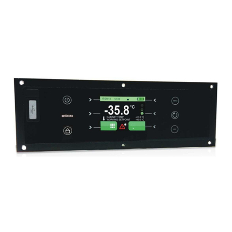
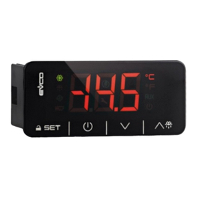
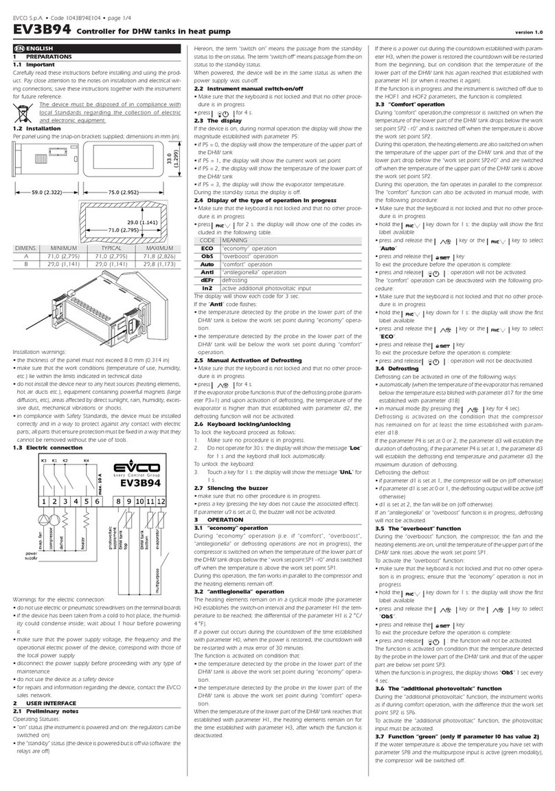
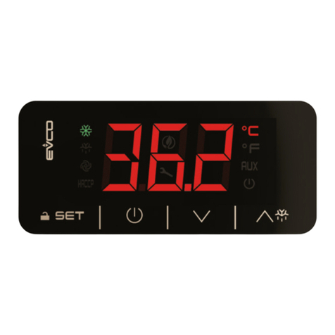
Evco EVK004 User manual

Evco S.p.A. • Code 104K004E05 • page 1/6
EVK004 Digital controller for ventilated refrigerating units, with RTC, HACCP, Energy Saving and Multideck functions version 1.05
GB ENGLISH
1 PREPARATIONS
1.1 Important
Please read these instructions carefully prior to installation and use,
and follow all the precautions for installation and electrical connec-
tions; keep these instructions with the device for future consultation.
1.2 Installazion
For the panel, using the snap-on brackets supplied; the dimensions
are given in mm (in).
DIMENS. MIN TYPICAL MAX
A 71.0 (2.795) 71.0 (2.795) 71.8 (2.826)
B 29.0 (1.141) 29.0 (1.141) 29.8 (1.173)
Recommendations for installation:
• the panel thickness must not exceed 8.0 mm (0.314 in)
• ensure that the operating conditions (operating temperature, hu-
midity, etc.) are within the limits indicated in the technical data sheets
• do not install the device near to any sources of heat (heating ele-
ments, hot air conduits, etc.), equipment containing powerful mag-
nets (large diffusers, etc.), areas affected by direct sunlight, rain, hu-
midity, excessive dust, mechanical vibration or shock
• in compliance with safety regulations, the device must be installed
correctly, and in such a way as to protect against any contact with
electrical parts; all safety devices must be fixed so that they cannot be
removed without the use of tools.
1.3 Electrical connections
With reference to the electrical circuit diagram:
• the service controlled by the fourth output depends on param. P4
• the service controlled by the fourth output depends on param. u1
• port 1 (by request) is the serial port used for communication with the
monitoring system (by means of a serial interface, via TTL, using the
MODBUS communication protocol) or with the programming key;
the port must not be used for both purposes simultaneously
• port 2 (by request) is the port used for comm. with the remote indi-
cator; the indicator displays the quantity assigned by parameter P6.
Points to note in relation to electrical connections:
• do not use electric or pneumatic screw-wrenches on the terminal
board
• if the device has been moved from a cold to a warm environment,
condensation may have formed inside; please wait approx. one
hour prior to switching on
• ensure that the voltage, frequency and operational power of the
device are compatible with the local power supply
• disconnect the power prior to proceeding with any kind of main-
tenance operation
• do not use the device as a safety device
• for repairs and any information relating to the device, contact the
Evco dealer network.
2 USER INTERFACE
2.1 Introductory comments
The device has the following operational states:
• "on" (power is connected and the device is on: the regulators may
be switched on)
• "stand-by" (power is connected but software sets the device to off:
the regulators are switched off; the option of manually switching
on/off the cabinet light or the auxiliary output depends on param-
eter u2).
The term "switching on" is understood to mean switching from the
stand-by state to on; the term "switching off" is understood to mean
switching from the on state to the stand-by state.
When the device is switched on, the status it was in when the power
was interrupted is restored.
2.2 Manual switching on/off of the device
• ensure the keyboard is not blocked and that no procedures are
running
• press for 4 s.
It is also possible to switch the device on/off using the multifunction
input.
2.3 The multideck function
If parameter P4 is set to 4, the Multideck will be active. In this case, the
temperature associated with the main regulator (i.e. the compressor)
will mainly be a function of the temperature detected by the cabinet
probe (in this application referred to as "air probe on") and the tem-
perature detected by the auxiliary probe (in this application referred
to as "air probe off").
The formula used to calculate the temperature (in this application re-
ferred to as "CPT temperature", Calculated Product Temperature) is s
follows:
CPT temperature = {(parameter P7 x air on temperature) + [(100 - pa-
rameter P7) x air off temperature]}
See also parameters d10 and d11.
If parameter P4 is set to 0, 1, 2 or 3, the Multideck function will not be
active.
In this case, the temperature associated with the main regulator (i.e. the
compressor) will be that of the cabinet.
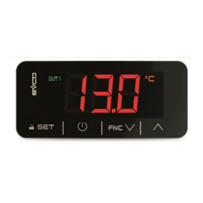
2.4 The display
If the device is switched on, then during normal operation the display
will show the quantity assigned by parameter P5:
• if P5 = 0 and P4 = 0, 1, 2 or 3, the display will show the temperature
of the cabinet; if P5 = 0 and P4 = 4, the display will show the CPT
temperature
• if P5 = 1, the display will show the operational setpoint
• if P5 = 2, the display will show the evaporator temperature
• if P5 = 3, the display will show "cabinet temperature - evaporator
temperature"
• if P5 = 4, the display will show the temperature detected by the
auxiliary probe (only if parameter P4 is set to 1, 2 or 4).
While in stand-by mode the display is switched off.
2.5 Displaying the cabinet temperature
• ensure the keyboard is not blocked and that no procedures are
running
• press for 2 s: the display will show the first available label
• press or to select “Pb1”
• press
To exit the procedure:
• press or do not operate the keypad for 60 s
• press or until the display shows the quantity assigned by
parameter P5 or do not operate the keypad for
60 s.
Alternatively:
• press
2.6 Displaying the evaporator temperature
• ensure the keyboard is not blocked and that no procedures are
running
• press for 2 s: the display will show the first available label
• press or to select “Pb2”
• press
To exit the procedure:
• press or do not operate the keypad for 60 s
• press or until the display shows the quantity assigned by
parameter P5 or do not operate the keypad for
60 s.
Alternatively:
• press
If there is no evaporator probe (parameter P3 = 0), label "Pb2" will not
be displayed.
2.7 Displaying the temperature detected by the auxiliary
probe (only if parameter P4 is set to 1,2 or 4)
• ensure the keyboard is not blocked and that no procedures are
running
• press for 2 s: the display will show the first available label
• press or to select “Pb3”
• press
To exit the procedure:
• press or do not operate the keypad for 60 s
• press or until the display shows the quantity assigned by
parameter P5 or do not operate the keypad for
60 s.
Alternatively:
• press
If the function of the fourth input is not that of the auxiliary probe
(parameter P4 = 0 or 3), then label "Pb3" will not be displayed.
2.8 Displaying the CPT temperature (only if parameter P4
is set to 4)
• ensure the keyboard is not blocked and that no procedures are
running
• press for 2 s: the display will show the first available label
• press or to select “CPt”
• press
To exit the procedure:
• press or do not operate the keypad for 60 s
• press or until the display shows the quantity assigned by
parameter P5 or do not operate the keypad for
60 s.
Alternatively:
• press
If the Multideck function is not active (parameter P4 = 0, 1, 2 or 3), then
label "CPt" will not be displayed.
2.9 Manual activation of defrosting
• ensure the keyboard is not blocked and that no procedures are
running
• press for4 s.
If the function of the evaporator probe is that of the defrosting probe
(parameter P3 = 1) and on activation of defrosting the evaporator
temperature is above that established by parameter d2, then defrost-
ing will not be activated.
2.10 Manual switching on/off of the cabinet light (only if
parameter u1 is set to 0)
• ensure no procedures are running
• press
It is also possible to switch the cabinet light on/off remotely using the
microport and multifunction inputs; see also parameter u2.
2.11 Switching on the demister (only if parameter u1 is set
to 1)
• ensure the device is switched on and no procedures are running
• press for 2 s: the demister heater will be switched on for the
period of time established by parameter u6.
Manual switching off of the demister is not permitted.
2.12 Manual switching on/off of the auxiliary output (only
if parameter u1 is set to 2)
• ensure the keyboard is not blocked and that no procedures are
running
• press
It is also possible to switch the auxiliary output on/off using the
multifunction input.
If the auxiliary output has been switched on manually, then it will be
permitted to switch it off the same way (the same principle applies for
remote switching on); see also parameter u2.
2.13 Blocking/unblocking the keyboard
To block the keyboard:
• ensure no procedures are running
• press and for 2 s: the display will show "Loc" for 1 s.
If the keyboard is blocked, it will not be possible to:
• manually switch the device on/off
• display the cabinet temperature (using the procedure indicated in
paragraph 2.5)
• display the evaporator temperature (using the procedure indicated
in paragraph 2.6)
• display the temperature detected by the auxiliary probe (using the
procedure indicated in paragraph 2.7)
• display the CPT temperature (using the procedure indicated in para-
graph 2.8)
• manually activate defrosting
• manually switch the auxiliary output on/off
• view information pertaining to the HACCP alarms
• delete the HACCP alarm list
• modify the date and time
• change the operational setpoint using the procedure indicated in
paragraph 3.2 (the operational setpoint may also be set by means of
parameter SP)
• display the total hours of compressor operation
• delete the total hours of compressor operation.
These operations will cause the label "Loc" to be displayed for 1 s.
To unblock the keyboard:
• press and for 2 s: the display will show "UnL" for 1 s.
2.14 Buzzer mute
• ensure no procedures are running

Evco S.p.A. • Code 104K004E05 • page 2/6
• press any key (the first key press does not trigger the associated effect).
If parameter u1 is set to 4 (or the service controlled by the fourth output
is the alarm output) and parameter u4 is set to 1, then pressing he key
will also deactivate the alarm output.
3 SETTINGS
3.1 Setting the date and time (clock)
• ensure the keyboard is not blocked and that no procedures are
running
• press for 2 s: the display will show the first available label
• press or to select “rtc”.
To modify the year:
• press within 60 s: the display will show "yy" followed by the
last two digits of the year
• press or within 15 s.
To modify the month:
• press within 15 s: the display will show "nn" followed by the
two digits for the month
• press or within 15 s.
To modify the day of the month:
• press within 15 s: the display will show "dd" followed by the
two digits for the day
• press or within 15 s.
To modify the hours:
• press within 15 s: the display will show "hh" followed by the
two digits for the hour
• press or within 15 s.
To modify the minutes:
• press within 15 s: the display will show "nn" followed by the
two digits for the minutes
• press or within 15 s
• press or do not operate the keypad for 15 s.
To exit the procedure:
• press or until the display shows the quantity assigned by
parameter P5 or do not operate the keypad for
60 s.
Alternatively:
• press
3.2 Setting the operational setpoint
• ensure the keyboard is not blocked and that no procedures are
running
• press the LED will flash
• press or within 15 s; also see parameters r1, r2 and r3
• press or do not operate the keypad for 15 s.
It is also possible to set the operational setpoint by means of parameter
SP.
3.3 Setting the configuration parameters
To access the procedure:
• ensure no procedures are running
• press and for 4 s: the display will show “PA”
• press
• press or within 15 s to set “-19”
• press or do not operate the keypad for 15 s
• press and for 4 s: the display will show “SP”.
To select a parameter:
• press or
To select a parameter:
• press
• press or within 15 s
• press or do not operate the keypad for 15 s.
To exit the procedure:
• press and for 4 s or do not operate the keypad for 60 s.
Interrupt the device power supply after altering the param-
eters.
3.4 Resetting configuration parameter default values
• ensure no procedures are running
• press and for 4 s: the display will show “PA”
• press
• press or within 15 s to set “743”
• press or do not operate the keypad for 15 s
• press and for 4 s: the display will show “dEF”
• press
• press or within 15 s to set “149”
• press or do not operate the keypad for 15 s: the display will flash
"dEF" for 4 s, after which the device will exit the proce-
dure
• interrupt the power to the device.
Ensure that the parameter default values are appropriate,
particularly if the probes are PTC or Pt 1000 type.
4 HACCP
4.1 Introductory comments
The device is capable of storing up to 9 HACCP alarms, after which the
most recent alarm will overwrite the oldest.
The device can furnish the following information:
• the critical value
• the data and time at which the alarm occurred
• the alarm duration (from 1 minute to 99 hours and 59 minutes,
partial if the alarm is ongoing).
CODE ALARM TYPE (AND CRITICAL VALUE)
AL minimum temperature alarm (the minimum temperature
of the cabinet, the minimum CPT temperature or the mini-
mum temperature detected by the auxiliary probe during
the alarm state)
AH maximum temperature alarm (the maximum temperature
of the cabinet, the maximum CPT temperature or the maxi-
mum temperature detected by the auxiliary probe during
the alarm state)
id microport input alarm (the maximum temperature of the
cabinet or the maximum CPT temperature during the alarm
state); see also parameter i4
PF power failure alarm (the temperature of the cabinet or the
CPT temperature on restoration of the power supply); see
also parameter AA
Warnings:
•the device records minimum temperature alarms and
maximum temperature alarms providing the temperature
associated with the alarm is the cabinet
temperature(parameters A0 and A3 = 0 and parameter
P4 = 0, 1, 2 or 3), the CPT temperature (parameters A0 and
A3 = 0 and parameter P4 = 4) or the temperature meas-
ured by the auxiliary probe, providing its function is that
of display probe (parameter P4 = 1 and parameters A0 = 2
and A3 = 1)
•in order to avoid repeatedly recording power failure alarms,
disconnect the device power supply while in stand by
mode
•if the duration of a power failure alarm is such as to
cause a clock error, then the device will not provide any
information regarding alarm duration
•no alarms will be recorded if the device is in stand-by
mode.
When the cause of the alarm is resolved, the display returns to normal,
except in the case of a power failure alarm where normal display
function must be restored manually.
To restore the normal display manually:
• press any key.
If parameter u1 is set to 4 (or the service controlled by the fourth output
is the alarm output), then pressing any key will also deactivate the
alarm output.
The HACCP LED provides information relating to the status of the
HACCP alarm memory; please refer to paragraph 6.1.
4.2 Viewing HACCP alarm information
To access the procedure:
• ensure the keyboard is not blocked and that no procedures are
running
• press for 2 s: the display will show the first available label
• press or to select “LS”
• press the display will show the most recent alarm code, or one
of the codes reported in the table in paragraph 4.1 fol-
lowed by the number "1" (the higher the number follow-
ing the code, the older the alarm).
To select an alarm:
• press or (to select "AH3" for example).
To display the information relating to the alarm:
• press the HACCP LED will stop flashing and remain on and the
display will show the following information in succes-
sion (for example):
INFO MEANING
8,0 the critical value is 8.0 °C/8 °F
StA the display is about to show the data and time at which the
alarm occurred
y07 the alarm occurred in 2007 (continued ...)
n03 the alarm occurred in the month of march (continued ...)
d26 the alarm occurred on 26 March 2007
h16 the alarm occurred at 16 hours (continued ...)
n30 the alarm occurred at 16:30 hours
dur the display is about to show the alarm duration
h01 the alarm lasted for 1 hour (continued ...)
n15 the alarm lasted for 1 hour and 15 minutes
AH3 the selected alarm
The display shows each piece of information for 1 s.
To exit the information series:
• press the display will show the selected alarm.
To exit the procedure:
• exit the information series
• press or until the display shows the quantity assigned by
parameter P5 or do not operate the keypad for
60 s.
Alternatively:
• exit the information series
• press
If the instrument has stored no alarm, the label “LS” will not be shown.
4.3 Deleting the HACCP alarm list
• ensure the keyboard is not blocked and that no procedures are
running
• press for 2 s: the display will show the first available label
• press or to select “rLS”
• press
• press or within 15 s to set “149”
• press or do not operate the keypad for 15 s: the display will flash
"- - - -" for 4 s and the HACCP LED will be turned off, after
which the device will exit the procedure.
If the instrument has stored no alarm, the label “rLS” will not be shown.
5 COMPRESSOR OPERATION TIME COUNTER
5.1 Introductory comments
The device is capable of recording up to 9,999 hours of compressor
function, after which the number "9999" flashes.
5.2 Displaying the compressor operation time
• ensure the keyboard is not blocked and that no procedures are
running
• press for 2 s: the display will show the first available label
• press or to select “CH”
• press
To exit the procedure:
• press or do not operate the keypad for 60 s
• press or until the display shows the quantity assigned by
parameter P5 or do not operate the keypad for
60 s.
Alternatively:
• press
5.3 Resetting the compressor operation time
• ensure the keyboard is not blocked and that no procedures are
running
• press for 2 s: the display will show the first available label
• press or to select rCH”
• press
• press or within 15 s to set “149”
• press or do not operate the keypad for 15 s: the display will flash
"- - - -" for 4 s, after which the device will exit the procedure.
6 INDICATORS
6.1 Indicators
LED MEANING
compressor LED
if on then the compressor is on
if flashing:
• the operational setpoint is being changed
• compressor protection is ongoing (parameters C0, C1,
C2 and i7)
defrosting LED
if on, defrosting ongoing
if flashing:
• defrosting has been requested, but compressor protec-
tion is ongoing (parameters C0, C1 and C2)
• drip-draining is ongoing (parameter d7)
• refrigerant fluid heating is ongoing (parameter dA)
Evaporator fan LED
if on then the evaporator fan is on
if flashing, then evaporator fan stop is ongoing (parameter
F3)
HACCP HACCP LED
if on, you will have not shown all the information on the
HACCP alarms
if flashing, the instrument will have stored at least one new
HACCP alarm
if off, you will have shown all the information on the HACCP
alarms or you will have cancelled the list of the HACCP
alarms
Maintenance LED
if on, compressor maintenance will be required (param-
eter C10)
alarm LED
if on, an alarm state or an error is ongoing
on/stand-by LED
if on, the device is in stand-by mode
°Cdegree Celsius LED
if on, the unit of measurement for temperature is degrees
Celsius (parameter P2)
if flashing, then the Energy Saving function is in operation
(parameters r4, i5, HE1 and HE2)
°Fdegree Fahrenheit LED
if on, the unit of measurement for temperature is degrees
Fahrenheit (parameter P2)
if flashing, then the Energy Saving function is in operation
(parameters r4, i5, HE1 and HE2)
Multifunction LED
parameter u1 is set to 0 (i.e. the service control-
led by the fourth output is the cabinet light)
if on, the cabinet light will have been switched on manu-
ally
if flashing, the cabinet light will have been turned on re-
motely (parameter i0)
parameter u1 is set to 1, 4, 5, 6 or 7
if on, the service controlled by the fourth output will be
turned on
parameter is set to 2 (i.e. the service controlled
by the fourth output is the auxiliary output)
if on, the auxiliary output will have been turned on manu-
ally
if flashing, the auxiliary output will have been turned on
remotely (parameter i5)
parameter u1 is set to 3 (i.e. the service control-
led by the fourth output is compressor 2)
if on, compressor 2 is on
if flashing, compressor 2 delay is ongoing (parameter C9)
Evco S.p.A. • Code 104K004E05 • page 3/6
CODE MEANING
Loc the key and/or operational setpoint are blocked (param-
eter r3), refer to paragraph 2.13
- - - - the quantity for display is not available (e.g. the probe is
absent)
7 ALARMS
7.1 Alarms
CODE MEANING
AL Minimum temperature alarm (HACCP alarm)
Remedies:
•check the alarm temperature
• check parameters A0, A1 and A2
Main consequences:
• if parameter A0 is set to 0 or if parameter P4 is set to 1 and
parameter A0 is set to 2, the device records the alarms
• if parameter u1 is set to 4, the alarm output will be acti-
vated
AH Maximum temperature alarm (HACCP alarm)
Remedies:
• check the alarm temperature
• check parameters A3, A4 and A5
Main consequences:
• if parameter A3 is set to 0 or if parameter P4 is set to 1 and
parameter A3 is set to 1, the device records the alarms
• if parameter u1 is set to 4, the alarm output will be acti-
vated
id Microport input alarm (HACCP alarm)
Remedies:
• check the causes which activated the input
• check parameters i0, i1 andi4
Main consequences:
• the outcome set by parameter i0
• if parameter i4 is set to 1, the device records the alarms,
providing parameter i2 is not set to -1
• if parameter u1 is set to 4, the alarm output will be acti-
vated
PF Power failure alarm (HACCP alarm)
Remedies:
• check the causes of the power failure
• press any key
Main consequences:
• the device records the alarm; see also parameter AA
• if parameter u1 is set to 4, the alarm output will be acti-
vated; pressing any key will also deactivate the alarm
output
iA Input malfunction alarm (only if parameter P4 is set to 3)
Remedies:
• check the causes which activated the input
• check parameters i5 and i6
Main consequences:
• if parameter i5 is set to 4, the device will continue to
operate as normal
• if parameter i5 is set to 5, the compressor will be switched
off
• if parameter u1 is set to 4, the alarm output will be acti-
vated
iSd Device blocked alarm (only if parameter P4 is set to 3)
Remedies:
• check the causes which activated the input malfunction
• switch the device off then on, or disconnect the power
supply
• check parameters i5, i6, i7, i8 and i9
Main consequences:
• the regulators will be switched off
• if parameter u1 is set to 4, the alarm output will be acti-
vated
COH Condenser overheating alarm (only if parameter P4 is set
to 3)
Remedies:
• check the condenser temperature
• check parameter C6
Main consequences:
• if parameter u1 is set to 4, the alarm output will be acti-
vated
CSd Compressor blocked alarm (only if parameter P4 is set to 3)
Remedies:
• check the condenser temperature
• switch the device off and then on again: if on switching
back on again the condenser temperature is still above
the value established by parameter C7, it will be neces-
sary to disconnect the power supply and clean the con-
denser
• check parameter C7
Main consequences:
• the compressor and evaporator fan will be switched off
• if parameter u1 is set to 4, the alarm output will be acti-
vated
When the cause that triggered the alarm has been resolved, the device
will restore normal operation, except for the following alarm states:
• the power failure alarm (code "PF") requiring that a key be pressed;
if parameter u1 is set to 4 (i.e. the service controlled by the fourth
output is the alarm output), pressing any key will also deactivate the
alarm output
• the device blocked alarm (code "iSd") which requires the device be
switched off or the power supply disconnected
• the compressor blocked alarm (code "CSd") which requires the
device be switched off or the power supply disconnected.
8 INTERNAL DIAGNOSTICS
8.1 Internal Diagnostics
CODE MEANING
Pr1 Cabinet probe error
Remedies:
• see parameter P0
• check probe integrity
• check probe-device connection
• check the cabinet temperature
Main consequences:
• the activity of the compressor will depend on param-
eters C4 and C5
• defrosting will never be activated
• if parameter u1 is set to 4, the alarm output will be acti-
vated
• if parameter u1 is set to 5 or 6, the fourth output will be
deactivated
Pr2 Evaporator probe error
Remedies:
• the same as for the previous case, but in relation to the
evaporator probe
Main consequences if parameter P4 is set to 0, 1, 2 or 3:
• if parameter P3 is set to 1, defrosting will last for the du-
ration established by parameter d3
• if parameter P3 is set to 1 and parameter d8 is set to 2, the
device will operate as though parameter d8 was set to 0
• if parameter F0 is set to 3 or 4, the device will operate as
though the parameter was set to 2
• if parameter u1 is set to 4, the alarm output will be acti-
vated
Main consequences if parameter P4 is set to 4 and if param-
eter d10 is set to 0:
• the same as for the previous case
Main consequences if parameter P4 is set to 4 and if param-
eter d10 is set to 1:
• the auxiliary probe (air off probe) will function as the
evaporator probe
• the defrost end temperature will depend on parameter
d11
• if parameter F0 is set to 3 or 4, the device will operate as
though the parameter was set to 2
• if parameter u1 is set to 4, the alarm output will be acti-
vated
Pr3 Auxiliary probe error (only if parameter P4 is set to 1, 2 or
4)
Remedies:
• the same as for the previous case, but in relation to the
auxiliary probe
Main consequences if parameter P4 is set to 1 or 2:
• if parameter u1 is set to 4, the alarm output will be acti-
vated
Main consequences if parameter P4 is set to 4:
• the activity of the compressor will depend on param-
eters C4 and C5
• defrosting will never be activated
• if parameter u1 is set to 4, the alarm output will be acti-
vated
rtc Clock error
Remedies:
• reset the date and time
Main consequences:
• if parameter d8 is set to 3, the device will operate as though
the parameter was set to 0
• functions relating to date and time will not be available
(Energy Saving, HACCP, etc ...)
• if parameter u1 is set to 4, the alarm output will be acti-
vated
When the cause of the alarm is resolved, the device restores normal
operation, except for clock errors (code "rtc") which require the date
and time to be reset.
9 TECHNICAL DATA
9.1 Technical data
Case: grey self-extinguishing.
Front panel protection classification: IP 65.
Connections (usare solo conduttori in rame): screw terminal
blocks (power supply, inputs and outputs), 6 pin connector (serial
port; by request), 4 pin connector (to remote indicator; by request);
spring extractable terminal blocks (power supply, inputs and outputs)
by request.
Operating temperature: from 0 to 55ºC (from 32 to 131ºF, 10 ...
90% relative humidity, without condensation).
Power supply: 12 VAC/DC (or 12-24 VAC/DC), 50/60 Hz, 3.5 VA
(approximate) or 115 ... 230 VAC, 50/60 Hz, 5 VA (approximate).
If the instrument is supplied at 115 ... 230 VAC, protect the power
supply with a fuse rated 250 V, 1.25 A, 6.7 I2t.
Insulation class: 2.
Maintenance of clock data in absence of power supply: 24
hours will battery fully charged.
Battery charge time: 2 minutes without interruptions (the battery
is charged by the device power supply).
Alarm buzzer: available by request.
Sensor inputs: 2 (cabinet probe and evaporator probe) for PTC/
NTC/Pt 1000 probes.
Digital inputs: 1 (microport) for NA/NC contact (clean contact, 5 V,
1 mA); fourth input can be configured as sensor input (display probe,
condenser probe or air off probe, for PTC/NTC/Pt 1000 probes) or
digital input (multifunction, clean contact, 5 V, 1 mA).
Sensor range: from -50.0 to 150.0ºC (from -50 to 300ºF) for PTC
probes, from -40.0 to 105.0ºC (from -40 to 220ºF) for NTC probes,
from -100 to 150.0ºC (from -145 to 300ºF) for Pt 1000 probes.
Sensitivity: 0.1ºC/1ºC/1ºF.
Digital outputs: 4 relays:
•compressor relay: 16 A res. @ 250 VAC,
5 FLA, 30 LRA (exchange contacts)
•defrost relay: 8 A res. @ 250 VAC, 2 FLA,
12 LRA (exchange contacts)
•evaporator fan relay: 8 A res. @ 250 VAC,
2 FLA, 12 LRA (NA contacts)
•fourth output: 8 A res. @ 250 VAC, 2 FLA,
12 LRA (exchange contacts).
The maximum permitted current on loads is 10 A.
Serial port: port for communicating with the monitoring system (by
means of a serial interface, via TTL, using the MODBUS communica-
tion protocol) or with the programming key; by request.
Other communication ports: port for communicating with the
remote indicator; by request.
PT • 46/10

Evco S.p.A. • Code 104K004E05 • page 4/6
10 OPERATIONAL SETPOINT AND CONFIGURATION PARAMETERSE
10.1 Operational setpoint
MIN. MAX. U.O.M. DEF.
r1 r2 °C/°F (1) 0,0
10.2 Configuration paramaters
PARAM. MIN. MAX. U.O.M. DEF.
SP r1 r2 °C/°F (1) 0,0
PARAM. MIN. MAX. U.O.M. DEF.
CA1 -25,0 25,0 °C/°F (1) 0,0
CA2 -25,0 25,0 °C/°F (1) 0,0
CA3 -25,0 25,0 °C/°F (1) 0,0
P0 0 2 - - - - 1
P1 0 1 - - - - 1
P2 0 1 - - - - 0
P3 0 2 - - - - 1
P4 0 4 - - - - 3
P5 0 4 - - - - 0
P6 0 4 - - - - 0
P7 0 100 % 50
PARAM. MIN. MAX. U.O.M. DEF.
r0 0,1 15,0 °C/°F (1) 2,0
r1 -99,0 r2 °C/°F (1) -50,0
r2 r1 99,0 °C/°F (1) 50,0
r3 0 1 - - - - 0
r4 0,0 99,0 °C/°F (1) 0,0
PARAM. MIN. MAX. U.O.M. DEF.
C0 0 240 min 0
C1 0 240 min 5
C2 0 240 min 3
C3 0 240 s 0
C4 0 240 min 10
C5 0 240 min 10
C6 0,0 200,0 °C/°F (1) 80,0
C7 0,0 200,0 °C/°F (1) 90,0
C8 0 15 min 1
C9 0 120 s 5
C10 0 9999 h 1000
PARAM. MIN. MAX. U.O.M. DEF.
d0 0 99 h 8
d1 0 1 - - - - 0
d2 -99,0 99,0 °C/°F (1) 2,0
d3 0 99 min 30
d4 0 1 - - - - 0
d5 0 99 min 0
d6 0 1 - - - - 1
d7 0 15 min 2
d8 0 3 - - - - 0
d9 -99,0 99,0 °C/°F (1) 0,0
OPERATIONAL SETPOINT
operational setpoint
OPERATIONAL SETPOINT
operational setpoint
INGRESSI DI MISURA
cabinet probe offset
evaporator probe offset
auxiliary probe offset (only if P4 = 1, 2 or 4)
probe type
0 = PTC
1 = NTC
2 = Pt 1000
degree Celsius decimal point (for the quantity displayed during normal operation)
1 = YES
unit of temperature measurement (2)
0=°C
1=°F
evaporator probe function
0 = no probe
1 = defrosting probe and evaporator fan thermostat probe
2 = evaporator fan thermostat probe
fourth input function
0 = no probe
1 = sensor input (auxiliary probe, display probe)
2 = sensor input (auxiliary probe, condenser probe)
3 = digital input (multifunction input)
4 = sensor input (auxiliary probe, air off probe); refer to paragraph 2.3
quantity displayed during normal operation
0 = if P4 = 0, 1, 2 or 3, cabinet temperature
if P4 = 4, CPT temperature
1 = operational setpoint
2 = evaporator temperature
3 = "cabinet temperature - evaporator temperature"
4 = temperature detected by the auxiliary probe (only if P4 = 1, 2 or 4)
quantity displayed by the remote indicator
0 = if P4 = 0, 1, 2 or 3, cabinet temperature
if P4 = 4, CPT temperature
1 = operational setpoint
2 = evaporator temperature
3 = "cabinet temperature - evaporator temperature"
4 = temperature detected by the auxiliary probe (only if P4 = 1, 2 or 4)
percentage of air on temperature for calculating the CPT temperature (only if P4 = 4)
MAIN CONTROLLER
operational setpoint differential
minimum operational setpoint
maximum operational setpoint
block operational setpoint change (with the procedure indicated in paragraph 3.2)
1 = YES
temperature increase during Energy Saving function (only if P4 = 3 and i5 = 2 or 3); refer also to HE1 and HE2
COMPRESSOR PROTECTIONS (3)
compressor delay from device power on (4)
minimum time between two successive compressor operations; also compressor delay on resolution of cabinet probe error (if P4 = 4, also on resolution of auxiliary, air off
probe error) (5) (6)
minimum compressor shut-down time (5)
minimum compressor start-up time
duration of compressor shut-down during cabinet probe error (if P4 = 4, also during auxiliary probe, air off probe error); see also C5
duration of compressor start-up during cabinet probe error (if P4 = 4, also during auxiliary probe, air off probe error); see also C4
condenser temperature above which the condenser overheating alarm is activated (only if P4 = 2) (7)
condenser temperature above which the compressor block alarm is activated (only if P4 = 2)
compressor block alarm delay (only if P4 = 2) (8)
compressor 2 delay from power up of compressor 1 (only if u1 = 3)
number of hours of compressor operation above which maintenance request is indicated
0 = no function
DEFROSTING
defrost interval (only if d8 = 0, 1 or 2) (9)
0 = regular periodic defrosting will never be activated
type of defrosting
0 = electric
1= hot gas
defrost end temperature (only if P3 = 1)
defrost duration if P3 = 0 or 2; maximum defrost duration if P3 = 1
0 = defrosting will never be activated
defrosting at device power on (only if d8 = 1, 2 or 3) (4)
1 = YES
defrost delay from device power on (only if d4 = 1); see also i5 (4)
temperature displayed during defrosting (only if P5 = 0)
0 = cabinet temperature (if P4 = 4, CPT temperature)
1 = if, on activation of defrosting the cabinet temperature (if P4 = 4, the CPT temperature) is below the "operational setpoint + r0", at most "operational setpoint + r0"; if on
activation of defrosting the cabinet temperature (if P4 = 4, the CPT temperature) is above the "operational setpoint + r0", at most the cabinet temperature (if P4 = 4, the CPT
temperature) at activation of defrosting (10)
drip-drain duration
method of activation of defrosting
0 = PERIODIC - defrosting will be activated when the device has been left running for the length of time d0
1 = PERIODIC - defrosting will be activated when the compressor has been running for the length of time d0
2 = PERIODIC - defrosting will be activated when the evaporator temperature remains below the temperature set by d9 for the amount of time et by d0 (11)
3 = REAL TIME - defrosting will be activated at the times established by parameters Hd1 ... Hd6
the evaporator temperature above which the defrost interval count is suspended (only if d8 = 2)

Evco S.p.A. • Code 104K004E05 • page 5/6
d10 0 1 - - - - 0
d11 -99,0 99,0 °C/°F (1) 2,0
dA 0 99 min 0
PARAM. MIN. MAX. U.O.M. DEF.
A0 0 2 - - - - 0
A1 -99,0 99,0 °C/°F (1) -10,0
A2 0 2 - - - - 1
A3 0 1 - - - - 0
A4 -99,0 99,0 °C/°F (1) 10,0
A5 0 2 - - - - 1
A6 0 240 min 120
A7 0 240 min 15
A8 0 240 min 15
A9 0 240 min 15
AA 0 240 min 1
PARAM. MIN. MAX. U.O.M. DEF.
F0 0 4 - - - - 1
F1 -99,0 99,0 °C/°F (1) -1,0
F2 0 2 - - - - 0
F3 0 15 min 2
PARAM. MIN. MAX. U.O.M. DEF.
i0 0 5 - - - - 1
i1 0 1 - - - - 0
i2 -1 120 min 30
i3 -1 120 min 15
i4 0 1 - - - - 0
i5 0 7 - - - - 4
i6 0 1 - - - - 0
auxiliary probe (air off probe) function during evaporator probe error (only if P4 = 4); also auxiliary probe (air off probe) function when the evaporator probe is absent (only
if P4 = 4)
0 = auxiliary probe (air off probe); in this case:
DURING EVAPORATOR PROBE ERROR:
• if parameter P3 is set to 1, defrosting will last for the duration established by parameter d3
• if parameter P3 is set to 1 and parameter d8 is set to 2, the device will operate as though parameter d8 was set to 0
• if parameter F0 is set to 3 or 4, the device will operate as though the parameter was set to 2
WHEN THERE IS NO EVAPORATOR PROBE:
• defrosting will last for the length of time established by parameter d3
• if parameter d8 is set to 2, the device will operate as though parameter d8 was set to 0
• if parameter F0 is set to 3 or 4, the device will operate as though the parameter was set to 2
1 = like both auxiliary probe(air off probe) and evaporator probe
DURING EVAPORATOR PROBE ERROR:
• the defrost end temperature will depend on parameter d11
• if parameter P3 is set to 1 and parameter d8 is set to 2, the device will operate as though parameter d8 was set to 0
• if parameter F0 is set to 3 or 4, the device will operate as though the parameter was set to 2
WHEN THERE IS NO EVAPORATOR PROBE:
• the defrost end temperature will depend on parameter d11
• if parameter d8 is set to 2, the device will operate as though parameter d8 was set to 0
• if parameter F0 is set to 3 or 4, the device will operate as though the parameter was set to 2
defrost end temperature during evaporator probe error (only if P4 = 4 and d10 = 1); also defrost end temperature when there is no evaporator probe (only if P4 = 4 and
d10 = 1)
minimum compressor on duration on activation of defrosting so that they may be activated (only if d1 = 1) (12)
TEMPERATURE ALARMS
temperature associated with the minimum temperature alarm
0 = if P4 = 0, 1, 2 or 3, cabinet temperature; if P4 = 4, CPT temperature
1 = evaporator temperature (13)
2 = temperature detected by the auxiliary probe (only if P4 = 1, 2 or 4) (14)
the temperature below which the minimum temperature alarm is activated; see also A0 and A2 (7)
minimum temperature alarm type
0 = no alarm
1 = in relation to the operational setpoint (i.e. "operational setpoint - A1"; consider A1 to be without sign)
2 = absolute (i.e. A1)
temperature associated with the maximum temperature alarm
0 = if P4 = 0, 1, 2 or 3, cabinet temperature
if P4 = 4, CPT temperature
1 = temperature detected by the auxiliary probe (only if P4 = 1, 2 or 4) (14)
the temperature above which the maximum temperature alarm is activated; see also A3 and A5 (7)
maximum temperature alarm type
0 = no alarm
1 = in relation to the operational setpoint (i.e. "operational setpoint + A4"; consider A4 to be without sign)
2 = absolute (i.e. A4)
maximum temperature alarm delay on switching on device (only if A3 = 0 or if P4 = 1 and A3 = 1) (4)
temperature alarm delay
maximum temperature alarm delay on conclusion of evaporator fan stop (only if A3 = 0 or if P4 = 1 and A3 = 1) (15)
maximum temperature alarm delay on microport input deactivation (only if A3 = 0 or if P4 = 1 and A3 = 1) (16)
delay recording of power failure alarm
EVAPORATOR FAN
evaporator fan activity during normal operation
0 = off
1 = on
2 = in parallel with compressor
3 = dependent on F1 (17)
4 = off if the compressor is off, dependent on F1 if the compressor is on (17)
evaporator temperature above which the evaporator fan is switched off (only if F0 = 3 or 4) (7)
evaporator fan activity during defrosting and drip-draining
0 = off
1 = on (it is recommended that parameter d7 be set to 0)
2 = dependent on F0
evaporator fan stop duration
DIGITAL INPUTS
effect caused by activation of microport input; see also i4
0 = no effect
1 = the cabinet light will be switched on (only if u1 = 0, until the input is deactivated)
2 = the evaporator fan will be switched off (for up to the length of time set by i3 or until the input is deactivated)
3 = the compressor and evaporator fan will be switched off (for up to the length of time set by i3 or until the input is deactivated) (18)
4 = the evaporator fan will be switched off (for up to the length of time set by i3 or until the input is deactivated) and the cabinet light will be switched on (only if u1 = 0, until
the input is deactivated)
5 = the compressor and evaporator fan will be switched off (for up to the length of time set by i3 or until the input is deactivated) and the cabinet light will be switched on (only
if u1 = 0, until the input is deactivated) (18)
microport input contact type
0 = NA (input active with contact closed)
1 = NC (input active with contact open)
microport input alarm signal delay
-1 = the alarm will not be reported
maximum duration of the effect caused by activation of the microport input on the compressor and on the evaporator fan
-1 = the effect will last until the input will be disabled
recording of microport input alarm (19)
1 = YES
effect caused by activation of the multifunction input (only if P4 = 3)
0 = no effect
1 = DEFROST SYNCHRONISATION - after the period of time set by d5 defrosting will be activated
2 = ACTIVATION OF ENERGY SAVING FUNCTION - the Energy Saving function will be activated (until the input is deactivated); see also r4
3 = CLOSURE OF THE AWNING - the cabinet light will be turned off (only if u1 = 0 and only if switched on manually) and the Energy Saving function will be activated (until
the input is deactivated); see also r4
4 = ALARM ACTIVATION - after the amount of time set by i7 the display will flash the code "iA" and the buzzer will be activated (until the input is deactivated)
5 = TRIPPING THE PRESSURE SWITCH - the compressor will be switched off, the display will flash the code "iA" and the buzzer will be activated (until the input is deactivated);
see also i7, i8 and i9
6 = TURNING ON THE AUXILIARY OUTPUT - the auxiliary output will be turned on (only if u1 = 2, until the input is deactivated)
7 = SWITCHING OFF THE DEVICE - the device will switch to stand-by mode (until the input is deactivated)
type of multifunction input contact (only if P4 = 3)
0 = NA (input active with contact closed)
1 = NC (input active with contact open)

EVCO S.p.A. This document belongs to Evco; unless you are authorized by Evco, you can not publish this document.
Via Mezzaterra 6, 32036 Sedico Belluno ITALY Evco does not take any responsibility about features, technical data and possible mistakes related in this document.
Phone +39-0437-852468 • Fax +39-0437-83648 Evco does not take any responsibility about damages coming by the non-observance of additional information.
[email protected] • www.evco.it Evco reserves the right to make any change without prior notice and at any time without prejudice the basic safety and operating features.
Evco S.p.A. • Code 104K004E05 • page 6/6
i7 0 120 min 0
i8 0 15 - - - - 0
i9 1 999 min 240
PARAM. MIN. MAX. U.O.M. DEF.
u1 0 7 - - - - 0
u2 0 1 - - - - 0
u3 0 1 - - - - 1
u4 0 1 - - - - 0
u5 -99,0 99,0 °C/°F (1) -1,0
u6 1 120 min 5
u7 0,0 99,0 °C/°F (1) 2,0
u8 0 1 - - - - 0
PARAM. MIN. MAX. U.O.M. DEF.
HE1 00:00 23:59 h:min 00:00
HE2 00:00 23:59 h:min 00:00
PARAM. MIN. MAX. U.O.M. DEF.
Hd1 00:00 23:59 h:min - - : - -
Hd2 00:00 23:59 h:min - - : - -
Hd3 00:00 23:59 h:min - - : - -
Hd4 00:00 23:59 h:min - - : - -
Hd5 00:00 23:59 h:min - - : - -
Hd6 00:00 23:59 h:min - - : - -
PARAM. MIN. MAX. U.O.M. DEF.
LA 1 24 7 - - - - 247
Lb 0 3 - - - - 2
LP 0 2 - - - - 2
PARAM. MIN. MAX. U.O.M. DEF.
E9 0 1 - - - - 1
(1) the unit of measurement depends on parameter P2
(2) set appropriate regulator parameters after altering parameter P2
(3) if parameter u1 is set to 3, the service controlled by the fourth output will be compressor 2: compressor 1 and compressor 2 are referred to as "compressor"; compressor 2 operates in parallel with compressor
1, regardless of parameter C9
(4) the parameter is even effective after power supply interruption, such as when the device is switched on
(5) the time period established by the parameter is counted even while in stand-by mode
(6) if parameter C1 is set to 0, the cabinet probe error resolution delay (if P4 = 4, also from resolution of auxiliary probe, air off probe error) will be 2 minutes in any case
(7) the parameter differential is 2.0C/4F
(8) if, on device start-up, the condenser temperature is already above that established by parameter C7, parameter C8 will have no effect
(9) the device stores the defrost interval count every 30 minutes; altering parameter d0 has the effect of concluding the previous defrost interval or manual defrost activation
(10) the display is restored to normal operation when, the evaporator fan stop is concluded, the cabinet temperature (if P4 = 4, the CPT temperature) drops below that which blocked the display (or if a temperature alarm
occurs)
(11) if parameter P3 is set to 0 or 2, the device will operate as though parameter d8 was set to 0
(12) if, on defrost activation, the compressor on duration is less than the time established by parameter dA, the compressor will remain on for the fraction of time required to complete it
(13) if parameter P3 is set to 0, the device will operate as though parameter A0 was set to 0, but will not record the alarm
(14) if parameter P4 is set to 0 or 3, the device will operate as though the parameter was set to 0, but will not record the alarm
(15) during defrosting, drip draining and ventilator fan stop, there are no temperature alarms, if said occur following defrost activation
(16) there is no maximum temperature alarm while microport input is enabled, if occurring after input activation
(17) if parameter P3 is set to 0, the device will operate as though parameter F0 was set to 2
(18) the compressor is switched off 10 s after activation of the input; if the input is activated during defrosting or evaporator fan stop, activation will have no effect on the compressor
(19) the device records alarms occurring after the time established by parameter i2; if parameter i2 is set to -1, the device does not record the alarms
(20) ensure that the time established by parameter i7 s less than that established by parameter i9
(21) in order to avoid damage to the service connected, modify the parameter while in stand-by mode
(22) if the fourth output terminals are connected to the fourth input terminals of several devices, it will be possible to synchronise defrosting (providing that in each device, parameter P4 is set to 3, that parameter i5 is
set to 1 and parameter u1 is set to 7); in this case, drip-drain duration counting starts when defrosting of the last device is concluded
(23) it is recommended that parameter d7 for each device be set to the same value (different from 0 min); similarly, it is recommended to set parameter F3 for each device to the same value
(24) if parameter u2 is set to 0, switching off the device may cause switching off of the cabinet light or the auxiliary output (the service will remain off on subsequent switching on of the device); if parameter u2 is set
to 1, switching off the device does not cause switching off of the cabinet light or the auxiliary output (the service remains on on subsequent switching on of the device).
The device must be disposed of in accordance with local regulations pertaining to the collection of electrical and electronic appliances.
if i5 = 4, delayed multifunction input alarm notification (only if P4 = 3)
if i5 = 5, delayed multifunction input deactivation compressor delay (only if P4 = 3) (20)
number of multifunction input alarms such as to cause device block alarm (only if P4 = 3 and i5 = 5)
0 = no alarm
time that must elapse without multifunction input alarms so that the alarm counter is zeroed (only if P4 = 3 and i5 = 5)
DIGITAL OUTPUTS
service controlled by the fourth output (21)
0 = CABINET LIGHT - in this case, the important factors are: the key , parameters i0, i5 and u2
1 = DEMISTING HEATER - in this case, the important factors are: the key and parameter u6
2 = AUXILIARY OUTPUT - in this case, the important factors are: the key , parameters i5 and u2
3 = COMPRESSOR 2 - in this case, the important factor is parameter C9
4 = ALARM OUTPUT - the output is activated during an alarm and during an error; in this case the important factors are parameters u3 and u4
5 = DOOR ELEMENT - in this case the important factor is parameter u5
6 = EVAPORATOR VALVE - in this case the important factors are parameters u7 and u8
7 = DEFROST SYNCHRONISATION - the output works in parallel with the defrost output; in this case the important parameter is factor i5 (22) (23) enabling cabinet light or auxiliary
enables manual switching on/off of the cabinet light or auxiliary output while in stand-by mode (only if u1 = 0 or 2) (24)
1 = YES
alarm output polarity (only if u1 = 4)
0 = disabled during normal operation (the contact between terminals 6 and 7 will be open) and activated during an alarm and during an error (the contact between terminals
6 and 7 will be closed)
1 = activated during normal operation (the contact between terminals 6 and 7 will be closed) and disabled during an alarm and during an error (the contact between terminals
6 and 7 will be open)
enable alarm output deactivation with muting of buzzer (only if u1 = 4)
1 = YES
cabinet temperature (if P4 = 4, CPT temperature) above which the door element is switched off (only if u1 = 5) (7)
demisting heating duration (only if u1 = 1)
cabinet temperature (if P4 = 4, temperature CPT) below which the evaporator valve is deactivated (in relation to the operational setpoint, i.e. the "operational setpoint + u7")
(only if u1 = 6) (7)
evaporator valve contact type (only if u1 = 6)
0 = NA (valve active with contact closed)
1 = NC (valve active with contact open)
REAL TIME ENERGY SAVING
real time Energy Saving function activation time; see also r4 and HE2
real time Energy Saving function duration; see also r4 and HE1
00:00 = the real time Energy Saving function is never activated
REAL TIME DEFROSTING
first real time defrost activation time (only if d8 = 3)
--:-- = first real time defrost never activated
second real time defrost activation time (only if d8 = 3)
--:-- = second real time defrost never activated
third real time defrost activation time (only if d8 = 3)
--:-- = third real time defrost never activated
fourth real time defrost activation time (only if d8 = 3)
--:-- = fourth real time defrost never activated
fifth real time defrost activation time (only if d8 = 3)
--:-- = fifth real time defrost never activated
sixth real time defrost activation time (only if d8 = 3)
--:-- = sixth real time defrost never activated
SERIAL NETWORK (MODBUS)
device address
baud rate (0 = 2.400 baud, 1 = 4.800 baud, 2 = 9.600 baud, 3 = 19.200 baud)
parity
0 = none (no parity)
1= odd
2 = even
RESERVED
reserved
Table of contents
Other Evco Controllers manuals

Evco
Evco Vcolor 379 User guide

Evco
Evco EV3143 User manual

Evco
Evco EV3 MVC Series Instructions for use

Evco
Evco Vcolor 819 User guide

Evco
Evco Vcolor 579 User guide

Evco
Evco c-pro 3 NODE kilo User manual

Evco
Evco Vcolor 318 M User guide

Evco
Evco EV8318 User manual

Evco
Evco EVJ 800 series User guide

Evco
Evco EVJ 500 Series User manual

Evco
Evco EVJ 200 Series User manual

Evco
Evco Vcolor 338 L User guide

Evco
Evco EVBOX Light JS200 User manual

Evco
Evco EV3B71 User manual

Evco
Evco EVX225 User manual

Evco
Evco EV3 CHIL User guide

Evco
Evco EVK614 User manual

Evco
Evco Vcolor 539 Series User guide

Evco
Evco EVJ 700 User guide

Evco
Evco c-pro 3 micro CHIL Series Instructions for use