manuals.online logo
Brands
  1. Home
  2. •
  3. Brands
  4. •
  5. Extel
  6. •
  7. Intercom System
  8. •
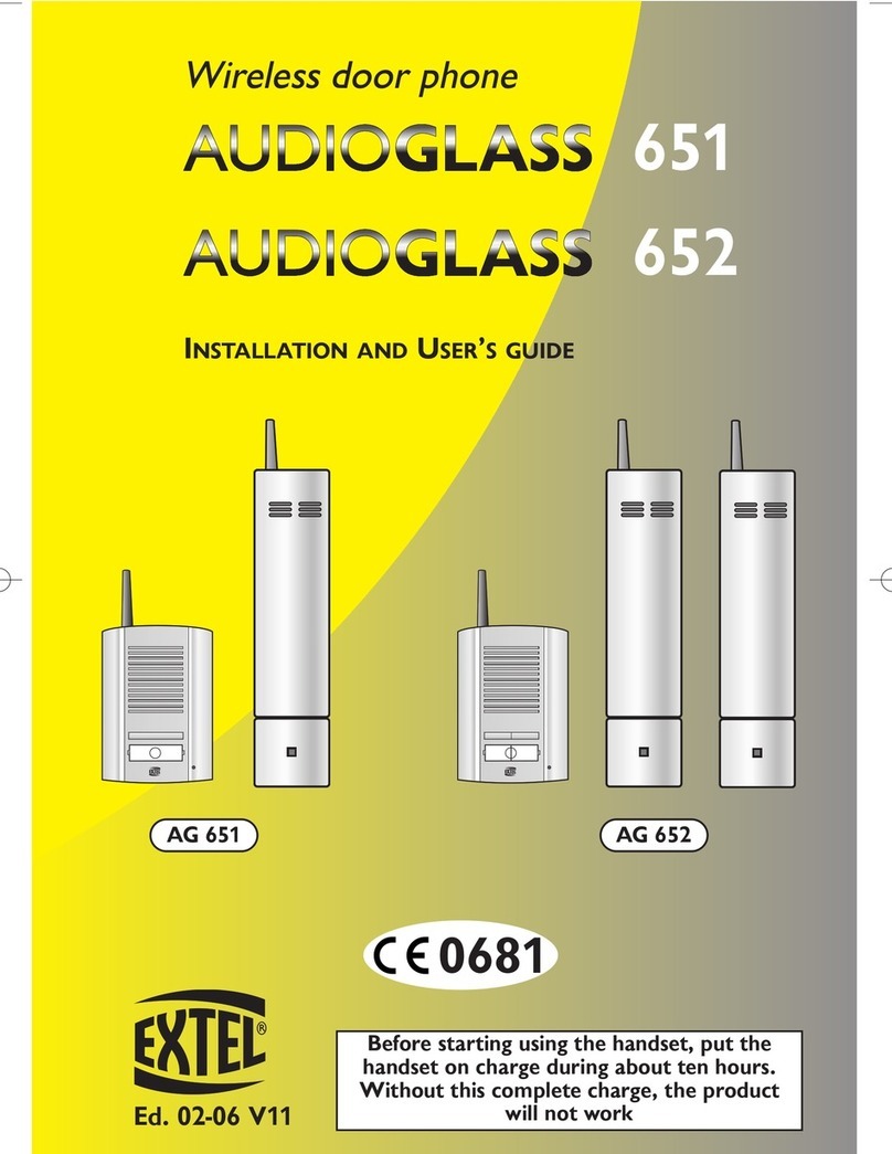
  9. Extel WEPA 242 User manual

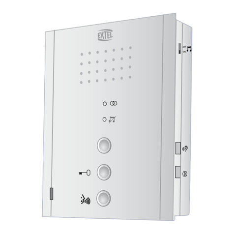
Extel WEPA 242 User manual

WEPA 242
WEPACB 243
Ed. 05-05
MODE D’EMPLOI ET D’INSTALLATION
HANDLEIDING VOOR INSTALLATIE EN GEBRUIK
INSTALLATIONS - UND BEDIENUNGSANLEITUNG
INSTALLATION AND OPERATION MANUAL
ISTRUZIONI DI UTILIZZO E INSTALLAZIONE
INSTRUCCIONES DE USO E INSTALACIÓN
MODO DE EMPREGO E DE INSTALAÇÃO
Manuel wePA 242 22/12/05 14:36 Page 2
2
Manuel wePA 242 22/12/05 14:36 Page 3
3
1. CHANGEMENT DE LA PLAQUE SUR LA PLATINE DE RUE
ET/OU L’ETIQUETTE AVEC LE NOM
a. Dégager les blocs bouton(s) et haut-parleur (fig. 1A et 1B).
b. Vous avez maintenant l’accès au porte-étiquette (fig. 1C).
c. Si vous devez changer uniquement le nom vous pouvez remonter les 2 blocs (fig. 1D).
d. Pour changer la face avant vous devez :
1 .Dévisser les 4 vis " d " pour dégager la partie plastique et les 4 vis " e " pour dégager l’étrier (fig. 1C).
2 .Assembler les 2 supports sur la nouvelle plaque en remontant l’étrier avec les 4 les vis " e " et les
supports en plastique avec les 4 vis " d ".
3 .Replacer les 2 blocs bouton(s) et haut-parleur (fig. 1D).
1A 1B
1C 1D
d
e
e
e
e
d
dd
e
d
Manuel wePA 242 22/12/05 14:36 Page 2
4
1. REPLACING THE FRONT PANEL AND/OR NAME PLATE ON
THE ROADSIDE PANEL
a. Release the button block(s) and loudspeaker (fig. 1A et 1B).
b. The name plate is now accessible (fig. 1C).
c. If only the name is to be changed, reassemble the two blocks (fig. 1D).
d. To replace the front panel:
1 .Unscrew the four screws (d) to release the plastic section and the four screws (e) to release
the cradle (fig. 1C).
2 .Assemble the two side pieces on the new panel, reattaching the cradle with the four screws (e) and
the plastic side pieces with the four screws.
3 .Replace the two button block(s) and the loudspeaker (fig. 1D).
1. VERVANGING VAN DE PLAAT OP DE STRAATUNIT EN/OF
HET ETIKET MET DE NAAM
a. De blokken met de knop(pen) en luidspreker vrijmaken (afb. 1A en 1B).
b. De etikethouder is nu toegankelijk (afb. 1C).
c. Voor de wijziging van de enkele naam kunnen de 2 blokken weer worden geïnstalleerd (afb. 1D).
d. Voor de vervanging van het front:
1 .de 4 schroeven " d " losdraaien om het kunststof gedeelte en de 4 schroeven " e " om de klem vrij
te maken (afb. 1C).
2 .de 2 plaatjes op de nieuwe plaat installeren door de klem met de 4 schroeven " e " en de kunsts-
tof plaatjes met de 4 schroeven " d " weer aan te brengen.
3 .De 2 blokken met de knop(pen) en luidspreker weer plaatsen (afb. 1D).
1. FRONTPLATTE DER AUSSENSTATION UND/ODER
NAMENSSCHILD AUSWECHSELN
a. Tasterblöcke mit dem eingebauten Lautsprecher aufklappen (abb. 1A und 1B).
b. Das Namensschild ist jetzt zugänglich (abb. 1C).
c. Soll nur der Name geändert werden, können Sie anschließend die Tasterblöcke wieder zuklappen (abb. 1D).
d. Zum Auswechseln der Frontplatte gehen Sie wie folgt vor:
1 .Vier Schrauben " d " herausdrehen und Kunststoffteil abnehmen; vier Schrauben " e " herausdrehen
und Bügelteil abnehmen (abb. 1C).
2 .Neue Frontplatte einsetzen. Dazu Bügelteil mit vier Schrauben " e " und Kunststoffteile mit vier
Schrauben " d " aufschrauben.
3 ..Beide Tasterblöcke mit dem eingebauten Lautsprecher wieder zuklappen (abb. 1D).
Manuel wePA 242 22/12/05 14:36 Page 3
5
1. SOSTITUZIONE DELLA PLACCA SUL MODULO ESTERNO
E/O L’ETICHETTA NOME
a. Sbloccare i blocchi pulsante(i) e l’altoparlante (fig. 1A et 1B).
b. È ora possibile accedere al porta-etichetta (fig. 1C).
c. Se si deve solo cambiare il nome, rimontare i 2 blocchi (fig. 1D).
d. Per cambiare anche la mascherina anteriore occorre invece :
1 .Svitare le 4 viti " d " per rimuovere la parte in plastica e le 4 viti " e " per rimuovere la staffa (fig. 1C).
2 .Assemblare i 2 dischetti sulla placca nuova rimontando la staffa con le 4 viti " e " e il dischetto in
plastica con le 4 viti " d .
3 .Riposizionare quindi i 2 blocchi pulsante(i) e l’altoparlante (fig. 1D).
1. CAMBIO DE LA PLACA Y/O DE LA ETIQUETA CON EL
NOMBRE EN LA PLETINA DE CALLE
a. Levante los bloques botón/botones y el altavoz (fig. 1A et 1B).
b. De este modo podrá acceder al portaetiqueta (fig. 1C).
c. Si sólo tiene que cambiar el nombre, puede volver a montar los 2 bloques (fig. 1D).
d. Para cambiar la parte delantera haga lo siguiente:
1 .Desatornille los 4 tornillos “d” para levantar la parte de plástico y los 4 tornillos “e” para levantar el
estribo (fig. 1C).
2 .Junte los 2 plásticos sobre la nueva placa volviendo a montar el estribo con los 4 tornillos “e” y los
plásticos con los 4 tornillos “d”.
3 .Vuelva a colocar los 2 bloques botón/botones y el altavoz (fig. 1D).
1. ALTERAÇÃO DO PAINEL NA PLACA DE RUA E/OU DA
ETIQUETA COM O NOME
a. Desprender os blocos do(s) botão(ões) e o altifalante (fig. 1A et 1B).
b. Você conseguiu, assim, o acesso ao porta-etiqueta (fig. 1C).
c. Se tiver apenas de alterar o nome pode tornar a montar os dois blocos (fig. 1D).
d. Para alterar o painel frontal você deve:
1 .Desaparafusar os 4 parafusos "d" para desprender a parte plástica, e os 4 parafusos " e " para des-
prender o estribo (fig. 1C).
2 .Colocar os 2 componentes sobre a nova placa, montando de novo o estribo com os 4 parafusos "
e ", e os componentes em plástico com os 4 parafusos " d ".
3 .Tornar a colocar as 2 consolas com o(s) botão(ões) e o altifalante (fig. 1D).
Manuel wePA 242 22/12/05 14:36 Page 4
6
2. ENCASTREMENT DE LA PLATINE / INBOUW VAN DE VER-
ZONKEN UNIT / AUSSENSTATION UNTERPUTZ
MONTIEREN / MOUNTING THE PANEL (FLUSH-MOUNTING)
INCASTRO DEL MODULO ESTERNO
EMBUTIDO DE LA PLETINA / COLOCAÇÃO DA PLACA
a. Ouvrir les volets des caches vis à l’aide d’un petit tournevis (fig. 2A,2B et 2C).
a. De klepjes van de schroefafdekkingen openen met een kleine schroevendraaier (afb. 2A,2B et 2C).
a. a. Schraubenabdeckungen mit einem kleinen Schraubenzieher aufklappen (fig. 2A,2B et 2C).
a. Use a small screwdriver to open the screw cover flaps (fig. 2A,2B et 2C).
a. Con un cacciavite piccolo, aprire i pannelli copri viti (fig. 2A,2B et 2C).
a. Abra los cubretornillos con un pequeño destornillador (fig. 2A,2B et 2C).
a. Retirar as tampas dos compartimentos dos parafusos com a ajuda de uma pequena chave de
parafusos (fig. 2A,2B et 2C).
b. Sceller la boîte d'encastrement au ras du mur, le cadre de la boîte venant en appui sur le mur (fig. 3 -
p.7).
c. Raccorder délicatement les fils sur les bornes (connexion sans outil), schéma (fig. 4 - p.15)
d. Remonter la platine de rue avec les 2 vis 6 pans fournis avec une clé.
e. Refermer les volets pour masquer la visserie.
b. Unterputzdose bündig in die Mauer einlassen: Die Vorderkante muss mit der Mauer fluchtend ausge-
richtet sein (fig. 3 - b.7).
c. Drähte vorsichtig anklemmen (kein Werkzeug erforderlich), s. Abb. (fig. 4 - b.15)
d. Frontplatte mit 2 Inbusschrauben befestigen (Inbusschrauben und -schlüssel mitgeliefert)
e. Schraubenabdeckungen zuklappen.
b. De inbouweenheid goed aansluitend in de muur verzegelen, waarbij het frame van de inbouweenheid
op de muur moet steunen (afb. 3 - s.7).
c. De draden voorzichtig met de klemmen verbinden (zonder gereedschap), schema afb. (afb. 4 - s.15)
d. De straatunit weer installeren met de 2 geleverde zeskante schroeven en een sleutel
e. De klepjes weer sluiten om het schroefwerk aan het zicht te onttrekken
2A 2B 2C
Manuel wePA 242 22/12/05 14:36 Page 5
7
b. Fissare la scatola d’incastro a livello del muro con il telaio appoggiato al muro (fig. 3 - p.7).
c. Collegare delicatamente i fili sui terminali (per il collegamento non si richiedono attrezzi), schema (fig. 4
- p.15)
d. Rimontare il modulo esterno fissando le 2 viti esagonali fornite con chiave
e. Richiudere i pannelli copri-vite.
b. Empotre la caja para embutir la pletina a ras de la pared. El marco de la caja quedará apoyado contra
la pared (fig. 3 - p.7).
c. Conecte con cuidado los cables a los bornes (conexión sin herramienta) esquema (fig. 4 - p.15)
d. Vuelva a montar la pletina de calle con los 2 tornillos hexagonales suministrados con una llave.
e. Coloque de nuevo los cubretornillos para ocultar los tornillos.
b. Fixar a caixa para encastre ao nível da parede, o encaixe da caixa deve apoiar-se sobre a parede (fig. 3
- p.7).
c. Ligar cuidadosamente os fios aos bornes (conexão sem necessidade de recorrer a ferramentas),
esquema (fig. 4 - p.15)
d. Tornar a montar a placa de rua com os 2 parafusos sextavados fornecidos com uma chave.
e. Tornar a colocar as tampas que disfarçam os parafusos.
b. Seal the flush-mounting box in the wall, with the frame pressing against the surface of the wall (fig. 3
- p.7).
c. Carefully connect the wires to the terminals (no tools needed) as shown on fig. 4 -p.15
d. Use a spanner to attach the roadside panel with the two hex head screws supplied.
e. Close the flaps to hide the screws.
3
170mm
42mm
120mm
Manuel wePA 242 22/12/05 14:36 Page 6
8
2. MONTAGE DE LA PLATINE EN SAILLIE / MONTAGE VAN DE
UITSPRINGENDE UNIT / AUSSENSTATION AUFPUTZ
MONTIEREN / MOUNTING THE PANEL (SURFACE MOUN-
TING) / MONTAGGIO DEL MODULO SPORGENTE
MONTAJE DE LA PLETINA EN SALIENTE / MONTAGEM DA
PLACA SALIENTE
a. Ouvrir les volets des caches vis à l’aide d’un petit tournevis (fig. 2A,2B et 2C).
a. Schraubenabdeckungen mit einem kleinen Schraubenzieher aufklappen(afb. 2A,2B en 2C).
a. Schraubenabdeckungen mit einem kleinen Schraubenzieher aufklappen( (abb. 2A,2B und 2C).
a. Use a small screwdriver to open the screw cover flaps (fig. 2A,2B et 2C).
a. Con un cacciavite piccolo, aprire i pannelli copri viti (fig. 2A,2B et 2C).
a. Abra los cubretornillos con un pequeño destornillador (fig. 2A,2B et 2C).
a. Retirar as tampas dos compartimentos dos parafusos com a ajuda de uma pequena chave de
parafusos (fig. 2A,2B et 2C).
2A 2B 2C
b. Het uitspringende frame op de muur bevestigen, waarbij het frame van de ombouw op de muur moet
steunen (afb. 5 - b.9).
c. De draden voorzichtig met de klemmen verbinden (zonder gereedschap), schema (afb. 4 - b.15).
d. De straatunit weer installeren met de 2 geleverde zeskante schroeven en een sleutel.
e. De klepjes weer sluiten om het schroefwerk aan het zicht te onttrekken.
b. Fixer le cadre saillie au mur, le cadre de la boîte venant en appui sur le mur (fig. 5 - p.9).
c. Raccorder délicatement les fils sur les bornes (connexion sans outil), schéma (fig. 4 - p.15).
d. Remonter la platine de rue avec les 2 vis 6 pans fournis avec une clé.
e. Refermer les volets pour masquer la visserie.
b. Aufputzdose an der Mauer befestigen, wobei der Rahmen auf der Mauer aufliegt (abb. 5 - s.9).
c. Drähte vorsichtig anklemmen (kein Werkzeug erforderlich), s. (abb. 4 - s.15).
d. Frontplatte mit 2 Inbusschrauben befestigen (Inbusschrauben und -schlüssel mitgeliefert).
e. Schraubenabdeckungen zuklappen.
Manuel wePA 242 22/12/05 14:36 Page 7
9
5
b. Attach the surface-mounting frame to the wall, with the frame pressing against the surface of the wall
(fig. 5 - p.9).
c. Carefully connect the wires to the terminals (no tools needed) as shown on fig. 4- p.15
d. Use a spanner to attach the roadside panel with the two hex head screws supplied.
e. Close the flaps to hide the screws.
b. Fissare a muro il telaio sporgente, con il telaio della scatola appoggiato al muro (fig. 5 - p.9).
c. Collegare delicatamente i fili sui terminali (per il collegamento non si richiedono attrezzi), schema (fig. 4 -
p.15).
d. Rimontare il modulo esterno fissando le 2 viti esagonali fornite con chiave.
e. Richiudere i pannelli copri-vite.
b. Fije el marco de sobreponer a la pared. El marco de la caja quedará apoyado contra la pared (fig. 5 -
p.9).
c. Conecte con cuidado los cables a los bornes (conexión sin herramienta) esquema (fig. 4 - p.15).
d. Vuelva a montar la pletina de calle con los 2 tornillos hexagonales suministrados con una llave.
e. Coloque de nuevo los cubretornillos para ocultar los tornillos.
b. Fixar a caixa de modo a ficar saliente relativamente à parede, o encaixe da caixa deve apoiar-se sobre
a parede (fig. 5 - p.9).
c. Ligar cuidadosamente os fios aos bornes (conexão sem necessidade de recorrer a ferramentas), esquema
(fig. 4 - p.15).
d. Tornar a montar a placa de rua com os 2 parafusos sextavados fornecidos com uma chave.
e. Tornar a colocar as tampas que disfarçam os parafusos.
Manuel wePA 242 22/12/05 14:36 Page 8
10
3. FIXATION DU COMBINÉ
BEVESTIGING VAN DE HANDSET
SPRECHGERÄT INSTALLIEREN
MOUNTING THE HANDSET
FISSAGGIO DEL RICEVITORE
FIJACIÓN DEL TELÉFONO
FIXAÇÃO DO COMBINADO
a. Het bevestigingsrooster vrijmaken (afb. 6A).
b. Het rooster op de muur bevestigen met 4 schroeven (afb. 6B).
c. De draden aansluiten volgens het draadschema (afb. 4 - b.15).
d. De handset weer op de muursteun plaatsen.
a. Befestigungsrahmen lösen (abb. 6A).
b. Rahmen mit 2 Schrauben an der Wand befestigen (abb. 6B).
c. Drähte gemäß Verdrahtungsplan (abb. 4 - s.15) anschließen.
d. Sprechgerät in die Wandhalterung einhängen.
a. Dégager la grille de fixation (fig. 6A).
b. La fixer contre le mur à l’aide de 2 vis (fig. 6B).
c. Raccorder les différents fils en vous reportant au schéma
de câblage (fig. 4 - p.15).
d. Replacer le combiné sur son support mural.
a. Release the mounting slots (fig. 6A).
b. Fix it to the wall using 2 screws (fig. 6B).
c. Connect the various wires, as shown on the wiring diagram (fig. 4 - p.15).
d. Replace the handset on its wall bracket.
a. Sbloccare la griglia di fissaggio (fig. 6A).
b. Fissarla al muro con 2 viti (fig. 6B).
c. Collegare i vari fili facendo riferimento allo schema di cablaggio (fig. 4 - p.15).
d. Riposizionare il ricevitore sul supporto a muro.
a. Levante el soporte de fijación (fig. 6A).
b. Fíjelo contra la pared con 2 tornillos (fig. 6B).
c. Conecte los diferentes cables siguiendo el esquema de cableado (fig. 4 - p.15).
d. Vuelva a colocar el teléfono en su soporte de pared.
a. Desprender a grelha de fixação (fig. 6A).
b. Fixá-la à parede com 2 parafusos (fig. 6B).
c. Ligar os diversos fios recorrendo ao esquema de cablagem (fig. 4 - p.15).
d. Repor o combinado no seu suporte de parede.
6A 6B
Manuel wePA 242 22/12/05 14:36 Page 9
1011
4. MISE EN PLACE DU TRANSFORMATEUR /PLAATSING VAN
DE TRANSFORMATOR / TRAFO INSTALLIEREN /
INSTALLING THE TRANSFORMER / INSTALLAZIONE DEL
TRASFORMATORE / INSTALACIÓN DEL TRANSFORMADOR /
INSTALAÇÃO DO TRANSFORMADOR
a. Sur un rail DIN dans un tableau modulaire ou fixer sur un support avec les 2 pattes noires enclipsées
sur les côtés du transformateur. (fig. 7).
a. Attach the transformer to a DIN rail in a modular fusebox or to a flat surface using the two black lugs
clipped to the sides of the transformer (fig. 7).
a. Su guida DIN in un quadro modulare, oppure fissato su supporto con i due piedini neri applicati ai lati
del trasformatore.(fig. 7).
a. Sobre un raíl DIN en un cuadro modular o fijado en un soporte con las 2 patillas negras encajadas en
los laterales del transformador.(fig. 7).
a. Sobre uma calha DIN num módulo ou fixar num suporte com as 2 patilhas pretas seguras no
transformador (de lado). fig. 7).
a. Bevestiging op een DIN rail in een modulair bord of op een steun met de 2 zwarte pootjes die op de
zijkanten van de transformator worden geklikt (afb. 7).
a. Trafo auf einer DIN-Schiene installieren oder mit den 2 seitlich am Trafo eingerasteten schwarzen
Klammern auf einer Halterung befestigen (abb. 7).
7
Manuel wePA 242 22/12/05 14:36 Page 10
12
5. CONSIGNES DE SÉCURITÉ / VEILIGHEIDSVOORSCHRIFTEN
SICHERHEITSHINWEISES / SAFETY INSTRUCTIONS
ISTRUZIONI DI SICUREZZA CONSIGNAS DE SEGURIDAD
CONSELHOS DE SEGURANÇA
Le transformateur devra impérativement être monté sur le rail DIN d'un tableau modulaire ou monté en
saillie sur un support non métallique, en utilisant les deux trous de fixation. Il est bien entendu que les
cache-borniers devront être obligatoirement remontés ; d'autre part le raccordement doit se faire sur
une installation électrique conforme à la norme NFC 15-100 pour la france, et UNE FOIS LE
CÂBLAGE COMPLETEMENT TERMINÉ.
Protection : le transformateur est équipé d'une protection thermique "PTC". En cas de dommage ou
court circuit il faut pour récupérer la protection du transformateur :
1. Débrancher l'alimentation 230V~(2 mn au minimum).
2. Effectuer la réparation si besoin.
3. Rebrancher l'alimentation 230V~.
Der Trafo muß unbedingt auf der DIN-Schiene einer Elektrotafel befestigt oder mithilfe der beiden dazu
vorgesehenen Löcher auf eine nicht metallische Befestigungsfläche Aufputz montiert werden. Am Trafo
sind unbedingt die Klemmenabdeckplatten anzubringen. Außerdem darf der Trafo nur an eine vor-
schriftsgemäß verlegte Elektroinstallation (in Frankreich gemäß Norm NFC 15-100) und auch auch
ERST NACH VOLLSTÄNDIGER VERDRAHTUNG angeschlossen werden.
Absicherung: Der Trafo verfügt über einen eingebauten thermischen Schutz (PTC). Im Schadensfall
oder bei einem Kurzschluss wird der Schutz des Trafos wie folgt wiederhergestellt:
1. Stecker aus der 230 V~-Steckdose ziehen (mind. 2 Min. ausgesteckt lassen).
2. Gegebenenfalls Fehler beheben.
3. Stecker in die 230 V~-Steckdose einstecken.
De transformator verplicht op de DIN rail van een mudulair bord of een niet-metalen steun (uitsprin-
gend) monteren door middel van de twee gaten. De afdekkingen van de strips weer aanbrengen en de
transformator aansluiten op een elektrische installatie volgens de norm NFC 15-100 (voor Frankrijk) NA
DE VOLLEDIGE BEDRADING.
Beveiliging: de transformator is voorzien van een thermische zekering “PTC”. Bij beschadiging of korts-
luiting moet de beveiliging van de transformator als volgt weer tot stand worden gebracht:
1. De 230 V ~voeding loskoppelen (minimaal 2 minuten).
2. Indien nodig de installatie repareren.
3. De 230 V ~voeding weer aansluiten.
Manuel wePA 242 22/12/05 14:36 Page 11
13
El transformador deberá ir obligatoriamente montado sobre el raíl DIN de un cuadro modular o mon-
tado en saliente sobre un soporte no metálico, utilizando los dos agujeros de fijación. A continuación
habrá que volver a poner los tapabornes. Por otra parte, el transformador deberá conectarse a una ins-
talación eléctrica conforme a la norma NFC 15-100 en el caso de Francia y UNA VEZ QUE EL
CABLEADO ESTÉ COMPLETAMENTE TERMINADO.
Protección: el transformador está provisto de una protección térmica “PTC”. En caso de daños o cor-
tocircuito, para recuperar la protección del transformador tendrá que:
1. Desconectar la alimentación 230V ~(2 minutos como mínimo).
2. Efectuar las reparaciones que fueren necesarias.
3. Conectar de nuevo la alimentación 230V~.
O transformador deverá ser obrigatoriamente montado numa calha DIN de um módulo ou montado de
modo a ficar saliente sobre um suporte não metálico, utilizando para o efeito, os dois furos para fixação.
É lógico que os tapa-bornes devem tornar a ser obrigatoriamente montados; por outro lado, a ligação
deve ser feita numa instalação eléctrica que esteja de acordo com a norma SEMPRE DEPOIS DA
TAREFA DE CABLAGEM COMPLETAMENTE TERMINADA.
Protecção: o transformador está equipado com uma protecção térmica “PTC”. Em caso de estrago ou
de curto circuito, para recuperar a protecção do transformador, deve-se:
1. Cortar a alimentação 230 V~(2 mn no mínimo).
2. Efectuar a reparação se for caso disso.
3. Tornar a ligar a alimentação 230 V~.
The transformer must be mounted to a DIN rail in a modular fusebox or surface-mounted on a non-metal
surface using the two mounting holes. The terminal block covers must be fitted. The unit should be
connected to an electrical installation meeting applicable standards (NFC 15-100 for France) AFTER
WIRING IS COMPLETELY FINISHED.
Protection : The transformer is fitted with a thermal cut-out. If a fault or short-circuit occurs the fol-
lowing steps should be taken to restore transformer protection.
1. Disconnect the 230 V AC power supply (for at least 2 minutes).
2. Repair as needed.
3. Reconnect the 230 V AC power supply.
Il trasformatore dovrà essere imperativamente montato sulla guida DIN di un quadro modulare oppure
sporgente su un supporto non metallico nei due fori di fissaggio. Resta inteso che si devono rimontare i
copri-terminali e che i collegamenti vanno eseguiti su un impianto elettrico conforme alla norma france-
se NFC 15-100 e solo DOPO AVER COMPLETATO IL CABLAGGIO.
Protezione: il trasformatore è dotato di protezione termica “PTC”. In caso di guasto o di cortocircui-
to, per ripristinare la protezione del trasformatore occorre:
1. Scollegare l’alimentazione 230V~(per almeno 2 minuti).
2. Eseguire la riparazione, se necessario.
3. Ricollegare l’alimentazione 230V~.
Manuel wePA 242 22/12/05 14:36 Page 12
14
6. CÂBLAGE
BEDRADING
VERDRAHTUNG
WIRING
CABLAGGIO
CABLEADO
CABLAGEM
a. Se reporter au schéma de câblage (fig 4).
Fils à utiliser :
• 4 fils 6 /10 mm jusqu’à 25 m
• 4 fils 1.5 mm2jusqu’à 100 m
a. Zie het draadschema (afb 4).
Geschikte draden gebruiken:
• 4 draden 6 /10 mm tot 25 m
• 4 draden 1.5 mm2tot 100 m
a. Siehe Verdrahtungsplan (abb 4).
Zu verwendende Drähte:
• Bis 25 m Verdrahtungslänge: 4x Drähte 6/10 mm
• Bis 100 m Verdrahtungslänge: 4x Drähte 1.5 mm2
a. See the wiring diagram (fig 4).
Wires to be used:
• four 0.6 mm wires for distances up to 25 m
• four 1.5 mm2wires for distances up to 100 m
a. Attenersi allo schema di cablaggio (fig 4).
Fili da utilizzare:
• 4 fili 6 /10 mm fino a 25 m
• 4 fili 1,5 mm2 fino a 100 m
a. Remítase al esquema de cableado (fig 4).
Cables que han de utilizarse:
• 4 cables 6 /10 mm hasta 25 m
• 4 cables 1,5 mm2hasta 100 m
a. Recorrer ao esquema de cablagem (fig 4).
Fios a utilisar:
• 4 fios 6 /10 mm até 25 m
• 4 fios 1.5 mm2até 100 m
Manuel wePA 242 22/12/05 14:36 Page 13
15
we PA 242
we PACB 243
7
8
7
8
we PACB 243
4
A
B
AB
Manuel wePA 242 22/12/05 14:36 Page 14
16
7. RACCORDEMENT ET COMMANDE D’UN OUVRE-PORTE
AANSLUITING EN BEDIENING VAN EEN DEUROPENER
ANSCHLUSS UND BEDIENUNG EINES ELEKTROTÜRÖFFNERS
CONNECTION AND CONTROLLING A DOOR OPENER
COLLEGAMENTO E COMANDO DI APERTURA PORTA
CONEXIÓN Y ACCIONAMIENTO DE UN ABREPUERTA
Une gâche ou une serrure électrique sera à raccorder sur les bornes 9 et 10 de la platine de rue (fig. 8).
Pour la commande d’un automatisme intercaler l’option WE 8111 bis entre les bornes 9 et 10 et les 2
bornes " commande externe " de votre automatisme (fig. 9).
La gâche, la serrure ou l’automatisme sera commandé par la touche " clef sur le ou les combinés.
Een schootplaat of elektrisch slot moet op de klemmen 9 en 10 van de straatunit worden aangesloten (afb. 8).
Voor de bediening van een automatisme moet de optionele WE 8111 bis tussen de klemmen 9 en 10
en de 2 klemmen " externe bediening " van uw automatisme worden aangesloten (afb. 9).
De schootplaat, het slot of het automatisme wordt bediend door middel van de " sleu ltoets op de
handset(s).
7 8 9 10 7 8 7 8 9 10 7 8
89
WE 8111 BIS
Manuel wePA 242 22/12/05 14:36 Page 15
17
An electric lock or strike may be connected to terminals 9 and 10 on the roadside panel (fig. 8).
To control an automatic gate opener, connect the optional WE 8111 BIS unit between terminals 9 and
10 and the two "external control" terminals on the automatic opener (fig. 9).
The strike, lock or automatic opener will be controlled by the "key" button on the handset(s).
Ein Elektroschloss bzw. -türöffner wird an die Klemmen 9 und 10 an der Außenstation angeschlossen
(abb. 8).
Zur Ansteuerung eines Torantriebs wird die Option WE 8111 BIS zwischen den Klemmen 9 und 10
und den 2 "Außensteuerungs"-Klemmen des Torantriebs (abb. 9) installiert.
Elektroschloss, -türöffner bzw. Torantrieb werden mit der "Schlü"-Taste am Sprechgerät bzw. an den
Sprechgeräten bedient.
Collegare un incontro elettrico, o una serratura elettrica, sui terminali 9 e 10 del modulo esterno (fig. 8).
Per il comando di un automatismo, inserire l’opzione WE 8111 bis tra i terminali 9 e 10 e i due terminali
di “comando esterno” dell’automatismo (fig. 9).
L’incontro elettrico, la serratura o l’automatismo sono attivati dal pulsante “chiav sul/sui ricevitori.
En los bornes 9 y 10 de la pletina de calle (fig. 8)se podrá conectar un cerradero o una cerradura eléctri-
ca. Para el accionamiento de un automatismo intercale la opción WE 8111 bis entre los bornes 9 y 10 y
los 2 bornes “accionamiento externo” de su automatismo (fig. 9).
El cerradero, la cerradura o el automatismo se accionará por medio de al tecla “llave” que se encuentra
en el/los teléfono(s).
Uma chapa-testa ou uma fechadura eléctrica deve ser ligada aos bornes 9 e 10 da placa de rua (fig. 8).
Para o comando de um automatismo, intercalar a opção WE 8111 bis entre os bornes 9 e 10 e os 2
bornes " comando externo " do seu automatismo (fig. 9).
A chapa-testa, a fechadura ou o automatismo serão comandados através da tecla " chav no ou nos
combinados.
Manuel wePA 242 22/12/05 14:36 Page 16
18
8. COMBINÉ SUPPLÉMENTAIRE
EXTRA HANDSET
ZUSÄTZLICHES SPRECHGERÄT
ADDITIONAL HANDSET
RICEVITORE SUPPLEMENTARE
TELÉFONO ADICIONAL
COMBINADO SUPLEMENTAR
Un combiné supplémentaire WEPACB 243 se raccorde sur le combiné principal (fig. 10).
Een extra handset WEPACB 243 wordt parallel aangesloten op de hoofdset (afb. 10).
Ein zusätzliches Sprechgerät WEPACB 243 wird parallel zum Hauptsprechgerät installiert - (Abb. 10).
An additional WEPACB 243 handset may be connected in parallel with the main handset (fig. 10).
È possibile collegare in parallelo al ricevitore principale un ricevitore supplementare WEPACB 243 (fig. 10).
El teléfono adicional WEPACB 243 se conecta en paralelo en el teléfono principal (fig. 10).
Um combinado suplementar WEPACB 243 liga-se em paralelo sobre o combinado principal (fig. 10).
10
30 m max.
6 x 6/10 mm
Manuel wePA 242 22/12/05 14:36 Page 17
19
9. INTERCOMMUNICATION ENTRE LES 2 COMBINÉS (OPTION WEPACB 243)
INTERCOMMUNICATIE TUSSEN DE 2 HANDSETS (OPTIE WEPACB 243)
INTERCOMFUNKTION (OPTION WEPACB 243)
INTERCOM BETWEEN THE TWO HANDSETS (OPTIONAL WEPACB 243)
COMUNICAZIONE TRA I 2 RICEVITORI (ACCESSORIO WEPACB 243)
INTERCOMUNICACIÓN ENTRE LES 2 TELÉFONOS (OPÇIÓN WEPACB 243)
INTERCOMUNICAÇÃO ENTRE OS DOIS COMBINADOS (OPÇÃO WEPACB 243)
La touche " tphvous permet d’appeler le deuxième combiné et de converser en toute discrétion.
(Cette fonction neutralise les appels de la platine de rue, le temps de la communication)
Met de toets " tphkan de tweede handset worden gebeld om discreet een gesprek te voeren.
(Tijdens de duur van de communicatie worden de oproepen van de straatunit door deze functie geneu-
traliseerd)
The "tp button can be used to call the second handset and communicate discreetly.
(Calls from the roadside panel are disabled while using the intercom function.)
10. RÉGLAGE DU VOLUME DE LA SONNERIE
INSTELLING VAN HET BELNIVEAU /
KLINGELLAUTSTÄRKE EINSTELLEN /ADJUSTING THE
RING VOLUME / REGOLAZIONE L VOLUME DELLA SUO-
NERIA / AJUSTE DEL VOLUMEN DE LA MELODÍA
REGULAÇO DO VOLUME DA CAMPAINHA
Le curseur 2 positions placé sur le côté du combiné vous permet de choisir 2 niveaux de sonnerie.
Met de 2-standen cursor aan de zijkant van de handset kan tussen 2 belniveaus worden gekozen.
Mit dem seitlich am Sprechgerät befindlichen 2-Stellenregler können Sie eine der zwei verfügbaren
Klingellautstärken einstellen.
Slide the two-position switch on the side of the handset to select high or low ring volume.
Il cursore a 2 posizioni posto sul lato del ricevitore consente di impostare 2 diversi livelli di suoneria.
El cursor de 2 posiciones situado en el lateral del teléfono le permitirá escoger 2 niveles de melodía.
O cursor 2 posições situado no combinado (de lado) permite-lhe escolher 2 níveis de toques.
Il pulsante " tphpermette di chiamare il secondo ricevitore e di conversare con discrezione.
(Questa funziona disattiva le chiamate dal modulo esterno per tutto il tempo della conversazione).
La tecla “telfle permitirá llamar al segundo teléfono y charlar en total discreción.
(Esta función neutraliza las llamadas de la pletina de calle el tiempo que dura la comunicación).
A tecla " tp permite-lhe ligar-se ao segundo combinado e conversar com toda a discrição.
(Esta função neutraliza as chamadas a partir da placa de rua e o tempo de comunicação)
Mit der "tph"-Taste können Sie mit dem zweiten Sprechgerät eine mithörgesperrte Sprechverbindung
herstellen.(Während der Dauer des internen Gesprächs ist die Verbindung mit der Außenstation
gesperrt).
Manuel wePA 242 22/12/05 14:36 Page 18
20
FR - Ne jetez pas les piles et les appareils hors d’usage avec les ordures ménagères. Les sub-
stances dangereuses qu’ils sont susceptibles de contenir peuvent nuire à la santé et à l’environ-
nement. Faites reprendre ces appareils par votre distributeur ou utilisez les moyens de collec-
te sélective mise à votre disposition par votre commune.
NL - De lege batterijen en oude apparaten niet met het huisvuil meegeven: deze kunnen
gevaarlijke stoffen bevatten die de gezondheid en het milieu schaden.
De oude apparaten door uw distributeur laten innemen of de gescheiden vuilinzameling van
uw gemeente gebruiken.
D - Verbrauchte Batterien und nicht mehr benützte Geräte sind Sondermüll. Sie enthalten
möglicherweise gesundheits- und umweltschädliche Substanzen.
Geben Sie alte Geräte zur fachgerechten Entsorgung beim Gerätehändler ab bzw. benutzen
Sie die örtlichen Recyclinghöfe.
GB - Don’t throw batteries or out of order products with the household waste (garbage). The
dangerous substances that they are likely to include may harm health or the environment.
Make your retailer take back these products or use the selective collect of garbage proposed
by your city.
I - Non gettare le pile e le apparecchiature fuori uso insieme ai rifiuti domestici. Le sostanze
dannose contenute in esse possono nuocere alla salute dell’ambiente. Restituire questo mate-
riale al distributore o utilizzare la raccolta differenziata organizzata dal comune.
E - No tire las pilas ni los aparatos inservibles con los residuos domésticos, ya que las sustan-
cias peligrosas que puedan contener pueden perjudicar la salud y al medio ambiente.
Pídale a su distribuidor que los recupere o utilice los medios de recogida selectiva puestos a su
disposición por el ayuntamiento.
P - Não junte as pilhas nem os aparelhos que já não se usam com o lixo caseiro. As substân-
cias perigosas que ambos podem conter podem ser prejudiciais para a saúde e para o ambien-
te. Entregue esses aparelhos ao seu lixeiro ou recorra aos meios de recolha selectiva ao seu
dispor.
Manuel wePA 242 22/12/05 14:36 Page 1

This manual suits for next models

1

Other Extel Intercom System manuals

Extel WEPA 245 BIS SER.R1 User manual

Extel

Extel WEPA 245 BIS SER.R1 User manual

Extel LOLA 4.2 User manual

Extel

Extel LOLA 4.2 User manual

Extel Nova User manual

Extel

Extel Nova User manual

Extel WEVP 626 E BIS Operating instructions

Extel

Extel WEVP 626 E BIS Operating instructions

Extel 720308 User manual

Extel

Extel 720308 User manual

Extel WEVPMH 001 User manual

Extel

Extel WEVPMH 001 User manual

Extel WESV 87052 User manual

Extel

Extel WESV 87052 User manual

Extel BUS PRO 2 User manual

Extel

Extel BUS PRO 2 User manual

Extel LUKA JS-V440N2 User manual

Extel

Extel LUKA JS-V440N2 User manual

Extel Look User manual

Extel

Extel Look User manual

Extel WECR 80515 SER.R1 User manual

Extel

Extel WECR 80515 SER.R1 User manual

Extel LUKA User manual

Extel

Extel LUKA User manual

Extel I TOUCH User manual

Extel

Extel I TOUCH User manual

Extel CB BUS PRO 3 User manual

Extel

Extel CB BUS PRO 3 User manual

Extel LILLY DF-PI201 User manual

Extel

Extel LILLY DF-PI201 User manual

Extel WECR 61004 User manual

Extel

Extel WECR 61004 User manual

Extel BORDY Ed. 03 - 2015 V2 User manual

Extel

Extel BORDY Ed. 03 - 2015 V2 User manual

Extel WEVP 2100 E R2 SERIES User manual

Extel

Extel WEVP 2100 E R2 SERIES User manual

Extel MULTI PRO User manual

Extel

Extel MULTI PRO User manual

Extel BUS PRO User manual

Extel

Extel BUS PRO User manual

Extel TOPTEL 200 User manual

Extel

Extel TOPTEL 200 User manual

Extel LEVO User manual

Extel

Extel LEVO User manual

Extel CB BUSPRO 2 User manual

Extel

Extel CB BUSPRO 2 User manual

Extel LENA 18 .2 User manual

Extel

Extel LENA 18 .2 User manual

Popular Intercom System manuals by other brands

Linear AE-1000 installation instructions

Linear

Linear AE-1000 installation instructions

urmet domus 1043/550 quick start guide

urmet domus

urmet domus 1043/550 quick start guide

Black Box EntraGuard Gold Telephone Entry/Intercom... Specifications

Black Box

Black Box EntraGuard Gold Telephone Entry/Intercom... Specifications

Ringmaster RM5000EX Operation manual

Ringmaster

Ringmaster RM5000EX Operation manual

Abus MODUVIS TVHS20 Series user manual

Abus

Abus MODUVIS TVHS20 Series user manual

Onq IS-0386 Instruction/installation sheet

Onq

Onq IS-0386 Instruction/installation sheet

HIK VISION DS-KV8202-IM user manual

HIK VISION

HIK VISION DS-KV8202-IM user manual

HIK VISION DS-KD8102 user manual

HIK VISION

HIK VISION DS-KD8102 user manual

HIK VISION Villa 6 Series user manual

HIK VISION

HIK VISION Villa 6 Series user manual

LaGard 3035 User operating instructions

LaGard

LaGard 3035 User operating instructions

Clear-Com WBS-670 operating instructions

Clear-Com

Clear-Com WBS-670 operating instructions

basIP AV-07T instruction manual

basIP

basIP AV-07T instruction manual

Grant's Automation IPI-101 installation manual

Grant's Automation

Grant's Automation IPI-101 installation manual

Clear-Com FreeSpeak II FSII-TCVR-24 user guide

Clear-Com

Clear-Com FreeSpeak II FSII-TCVR-24 user guide

HIK VISION DS-KIS703-P manual

HIK VISION

HIK VISION DS-KIS703-P manual

HIK VISION DS-KV8213 user manual

HIK VISION

HIK VISION DS-KV8213 user manual

nor-tec 73498 instruction manual

nor-tec

nor-tec 73498 instruction manual

HIK VISION DS-KIS703-P manual

HIK VISION

HIK VISION DS-KIS703-P manual

manuals.online logo
manuals.online logoBrands
  • About & Mission
  • Contact us
  • Privacy Policy
  • Terms and Conditions

Copyright 2025 Manuals.Online. All Rights Reserved.