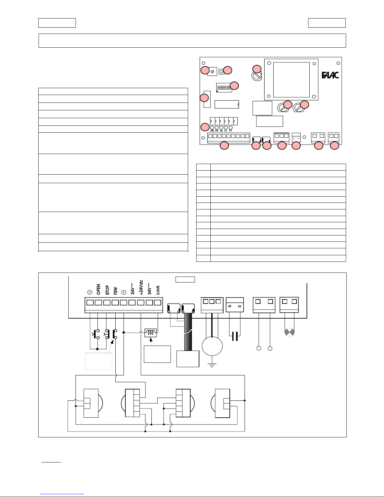
FAAC 844 MPSR User manual

844 MPSR
844 MPSR
C
E
R
M
E
T
A
Z
I
E
N
D
A
C
E
R
T
I
F
I
C
A
T
A
UNI EN ISO 9001-085
para la naturaleza
100% papel reciclado
ist umweltfreundlich
100% Altpapier
pour la nature
papier recyclé 100%
for nature
recycled paper 100%
carta riciclata 100%
per la natura

7
ENGLISH
ENGLISH EC COMPLIANCE DECLARATION
Manufacturer: FAAC S.p.A.
Address: Via Benini, 1
40069 - Zola Predosa
BOLOGNA - ITALY
Hereby declares that: the 844 MPSR electronic control unit
•complieswiththeessentialsafetyrequirementsinthefollowingEECDirectives:
73/23 EEC and subsequent amendment 93/68 EEC.
89/336 EEC and subsequent amendments 92/31 EEC and 93/68 EEC.
Additional note:
This product has been tested in a typical homogeneous configuration (all
products manufactured by FAAC S.p.A.).
Bologna, 1 January 1997
Managing
Director
A. Bassi

8
ENGLISH ENGLISH
IMPORTANT NOTICE FOR THE INSTALLER
GENERAL SAFETY INSTRUCTIONS
1) WARNING!Forreasonsofsafety,alltheinstructionsinthismanualmustbeobservedscrupulously.Improperinstallation
or misuse of the product may result in serious injury.
2) Read the instructions carefully before installing the product.
3) Packaging material (plastic, polystyrene etc.) is a potential hazard and must be kept out of reach of children.
4) Keep these instructions for future reference.
5) This product has been designed and manufactured only for the use stated in this manual. Any use other than that
expressly indicated may result in damage to the product and/or risk of injury.
6) FAACS.p.A.shallnotbeliableforanydamageorinjurycausedbyimproperuseoftheautomationorbyanyuseother
than that for which it is intended.
7) Do not install this device in explosive atmospheres: the presence of flammable gas or fumes is a serious hazard.
8) Mechanical structural elements must comply with UNI8612, CEN pr EN 12604 and CEN pr EN 12605 standards.
ForcountriesoutsidetheEC,mechanicalstructuralmustcomplywiththeabovestandardsinadditiontoanynational
safety standards, in order to obtain a reasonable degree of safety.
9) FAACcannot be held responsible for failure to observetechnical standards in the construction of the gateson which
the automation is installed, or for any deformation of the gates which may occur during use.
10) Installation must comply with UNI8612, CEN pr EN 12453 and CEN pr EN 12635.
The degree of safety of the automation must be C+D.
11) Before carrying out any operations on the system, disconnect the electrical power supply.
12) Install a multi-pole switch on the supply line to the automation with a contact opening distance of 3 mm or more. We
recommend the use of a 6A thermal magnetic circuit breaker with multi-pole switching.
13) Ensure that a residual current device with a trip threshold of 0.03A is installed upstream of the automation system.
14) Check that the earthing system is installed correctly and is efficient. Connect the metal parts of the gate and the
yellow/green wire of the operator to the earthing system.
15) The automation is fitted with an anti-crushing safety system consisting of a torque control device which, in all cases,
must be used in conjunction with other safety devices.
16) Thesafetydevices(e.g.photocells,safetyedges,etc.)protectareaswherethereisamechanicalmovementhazard,
e.g. crushing, entrapment and cutting.
17) Each installation must be fitted with at least one flashing light (e.g. FAAC LAMP, MINILAMP etc.) and a warning sign
suitably fixed to the gate, in addition to the safety devices as per point 16 above.
18) FAAC cannot be held responsible for the safe and correct operation of the automation in the event that parts other
than FAAC original parts are used.
19) Use only FAAC original spare parts for maintenance operations.
20) Do not carry out any modifications to automation components.
21) The installer must supply all information regarding manual operation of the system in the event of an emergency and
provide the end-user with the "End-user Guide" supplied with the product.
22) Do not allow any persons, especially children, to stand in the vicinity of the automation when in operation.
23) Keep the remote radio controls and any other control devices out of the reach of children to prevent accidental
operation of the automation.
24) The end-user must not attempt to repair or adjust the automation. These operations must be carried out exclusively
by qualified personnel.
25) Any operations not explicitly described in these instructions are not permitted.

9
ENGLISH
ENGLISH
These instructions apply to the following models:
844MPSR ELECTRONIC CONTROL UNIT
1. TECHNICAL CHARACTERISTICS
844 MPSR
Fig. 2
J4J3
J2
CH-DXCH-SX
1 2 3 4 5 6 7 8 9
M
1
2
1
2
3
4
5
J5 J6 J8 J7
230V~ 50Hz
(+6% -10%)
C
35µF
FAACLAMP
MINILAMP
Elettroserratura
Electric lock
Electroserrure
Elektrochloss
Electrocerradura
844MPSR
LN (L)
FINECORSA
LIMIT SWITCH
FIN DE COURSE
ENDSCHALTER
FIN DE CARRERA
1
2
3
4
5
1
2
Altre sicurezze
Other safeties
Autres sécurités
Andere Sicherheiten
Otros disp. seg.
ab
2.
ELECTRICAL CONNECTIONS
Fig. 1
1. 1. 844MPSR LAY-OUT
P1
RESET
TR1
BRAKE
F2
F1
F3
J7
J8
J6
J5
J4J3
J2
CH-DXCH-SX
J1
DS1
RL1
RL2
IC1
1 2 3 4 5 6 7 8 9
844MPSR
F1F3
P1
TR1
J1
Led
J2 J5 J7
J3 J4
DS1
F2
J6 J8
Ü
Always disconnect the electrical power supply before carrying
out any operations on the control unit (connections, program-
ming, maintenance).
Warning: On disconnecting connector J6, high voltages may be
present on the capacitor output.
Table. 1 TECHNICAL CHARACTERISTICS OF 844MPSR
Power supply 230V~ (+6 -10 %) 50Hz
Motor max. load 650 W
Accessories power supply 24Vdc/24Vac
Accessories max. load 500 mA
Warning light power supply 12Vac (5W max)
Temperature range - 20°C + 55°C
transformer primary
Fuses motor
accessories
for decoding cards or RP receivers
Quick connectors capacitor
limit switch
Inputs OPEN/STOP/CLOSING SAFETY/LIMIT-SWITCH
electric lock
Outputs flashing light
motor
24Vdc/24V~power supply for accessories
pause time (5-10-15-30-60-120-180 sec.)
Logic programming (automatic A1/S1/S2 - semiautomatic E1)
pre-flashing
Motor braking Adjustable by trimmer
Safety timing 255 sec.
Observe points 10, 11, 12, 13 and 14 in the GENERAL SAFETY
INSTRUCTIONS.
Always route the power supply cables separately from the control
andsafetycables(keyswitch,receiver,photocells,etc.).Useseparate
conduits to avoid any interference.
TAB. 2 844MPSR Control unit components
F1 Fast-acting fuse F1 5x20 F5A/250V (motor )
F2 Time delay fuse F2 5x20 T1.6A/250V (accessories)
F3 Time delay fuse F3 5x20 T250mA/250V (transformer)
P1 RESET button
TR1 Braking adjustment trimmer
DS1 Programming dipswitches
Led Input status indicator LEDs
J1 Quick connector for decoding cards/RP receiver
J2 Low voltage inputs/accessories terminal block
J3 Quick connector for limit switch (LH closure)
J4 Quick connector for limit switch (RH closure)
J5 Motor output terminal block
J6 Quick connector for capacitor
J7 Flasher unit output terminal block (230V
~ max 60W)
J8 Line input terminal block

10
ENGLISH ENGLISH
3. DESCRIPTION
3.1. CONNETOR J1
The connector J1 is used for the quick connection of
MINIDEC,DECODER, RP RECEIVER boards (Figs. 3, 4, 5).
Accessory boards are to be inserted with their component
sides facing the inside of the 844MPSR electronic control unit.
Always disconnect the power supply before inserting or
removing accessory boards.
Fig. 5
Fig. 4Fig. 3
MINIDEC
SL/DS
PLUS
844MPS
DECODER
SL/SLP/DS
844MPS
844MPS
844
MPSR
844
MPSR
844
MPSR
3.2. TERMINAL BLOCK J2 (low voltage)
1
&
5
=Common/Negative of accessory power supply (-)
2 = OPEN control device (N.O.)
Any control device (pushbutton,detector,..) which,
on closing the contact,relays an open and/or close
impulse to the gate.
To install more than one Open control device, con-
nect the N.O.contacts in parallel.
3 = STOP control device (N.C.)
Any control device (e.g. pushbutton) which, on
opening a contact,stops the movement of the gate.
To install more than one Stop control device, con-
nect the N.C.contacts in series.
ÜIf no Stop control devices are to be connected,
place a jumper across the input and the common
terminal (terminal 1 or 5).
4 = FSW closure safety device (N.C.)
Any control device (photocells, safety edges,mag-
netic loops) with an N.C. contact which interrupts
the movement of the gate when an obstacle is de-
tected within the protected area.
The task of the closure safety device is to safeguard
the area occupied by the gate during the closing
movement.
The intervention of safety devices during gate clo-
sure causes the direction of gate movement to be
reversed. These devices do not intervene during
gate opening movements.If a closure safety device
is tripped when the gate is open or during a pause
time,they will prevent gate closure.
To install more than one safety device, connect the
N.C. contacts in series.
ÜIf no closure safety devices are to be installed,
place a jumper across this input and the common
terminal (terminal 1 or 5).
6
&
8
=24V~ accessories power supply
The maximum load of the accessories is 500 mA.
To calculate power draw,refer to the instructions for
the individual accessories.
7 = 24Vdc accessories power supply positive (+)
The maximum load of the accessories is 500 mA.
To calculate power draw,refer to the instructions for
the individual accessories.
9 = Electric lock output (12 Vac)
For operation of the electric lock, refer to the
dipswitch settings.If two electric locks are installed,
they must be connected in series.
5.2.3. CONNECTORS J3-J4 (limit switch)
J3 = Connection of limit switch for left-hand closure
J4 = Connection of limit switch for right-hand closure
Refer to Figs. 6-7 for quick connection of the inductive limit
switch sensor for the corresponding gate closure direction.
3.4. TERMINAL BLOCK J5 (high voltage)
Terminal block for motor
connection.
ÜConnect the wires to
the terminals of J5 as
shown in Fig.8.
B
LACK
AND
B
ROWN
WIRES
=
electric motor supply
phases
B
LUE
WIRE
= electric motor
common
3.5. CONNECTOR J6 (high voltage)
Connector for quick connection of the capacitor.
3.6. TERMINAL BLOCK J7 (high voltage)
230V~ terminal block for connection of the flashing light (max
60W).
Fig. 7
J4J3
CH-DXCH-SX
844MPSR
J5
Fig. 6
J4J3
CH-DXCH-SX
844MPSR
J5
M
J5
BROWNBLACK
BLUE
Fig. 8

11
ENGLISH
ENGLISH
Fig. 9
3.7. TERMINAL BLOCK J8 (high voltage)
Terminalblock forconnection of the 230V~ 50Hz power supply
(L=Line N=Neutral).Connecttheearthwiretotheoperatoras
shown in Fig.9
3.8.
INDICATOR LEDS
5 LEDs on the board indicate the status of the terminal inputs
(see Table 3 and Fig. 10):
L
ED
ON
= contact closed
L
ED
OFF
= contact open
TABLE 3 MEANING OF STATUS INDICATOR LEDS
LED ON OFF
OPEN
Command active Command not active
STOP
Command not active Command active
FSW
Safeties disengaged Safeties engaged
FCC
Closing limit disengaged Closing limit engaged
FCA
Opening limit disengaged Opening limit engaged
Fig. 10
J2
1 2 3 4 5 6 7 8 9
(1) With the pre-flashing selected, movement starts after 5 seconds.
(2) If the impulse is sent during pre-flashing, the timer is reset to zero.
LOGIC S1 IMPULSES
GATESTATUS
CLOSED
OPEN
CLOSING
OPENING
STOPPED
OPEN
opensandreclosesafter
pausetime (1)
reclosesimmediately
(1 and 2)
invertsmotion
invertsmotion
recloses(1)
STOP
noeffect
stopscounting
stops
stops
noeffect
SAFETY
noeffect
recloses after 5 s
fromdisengagement
invertsmotion
noeffect
noeffect
TABLE 5 LOGIC S1 (SAFETY)
LOGIC S2 IMPULSES
STOP
noeffect
stopscounting
stops
stops
noeffect
GATESTATUS
CLOSED
OPEN
CLOSING
OPENING
STOPPED
OPEN
opensandreclosesafter
pausetime (1)
reclosesimmediately
(1 and 2)
invertsmotion
invertsmotion
recloses(1)
SAFETY
noeffect
freezespauseuntil
disengagement
stopsandinverts motion
whendisengaged(1)
noeffect
noeffect
TABLE 6 LOGIC S2 (SAFETY PLUS)
TABLE 7 LOGIC E1 (SEMI-AUTOMATIC)
SAFETY
noeffect
noeffect
invertsmotion
noeffect
noeffect
GATESTATUS
CLOSED
OPEN
CLOSING
OPENING
STOPPED
OPEN
opens(1)
recloses(1)
invertsmotion
stops
recloses (reopens when safety
devices are engaged) (1)
STOP
noeffect
noeffect
stops
stops
noeffect
IMPULSES
LOGIC E1
4.
DIPSWITCH SETTINGS
Toprogramtheoperationoftheautomation,setthedipswitches
as shown in the diagram above.
ÜPress the RESET button after all programming operations.
Operating logics
There are four operating logics available:
A1 = Automatic S1 = Safety
S2 = Safety Plus E = Semi-automatic
Operation of the different logics is described in tables 4- 5-6-7.
Pause time
The pause time is amount of time the gate remains open
beforeitre-closeswhenanautomaticcontrollogicisselected.
Pause times include the pre-flashing time, if selected.
Operation of electric lock(s)
Allowsyoutochoosewhethertheelectriclockistobeactivated
only before opening or also before closing. In both cases the
lockisreleasedonlywhentherespectivelimitswitchisengaged
(e.g.itis releasedbeforeopeningonlyiftheclosurelimitswitch
is activated).
Pre-flashing
Itis possibletoselect5secondspre-flashingoftheflashinglight
before any gate movement. This serves to warn any persons in
the vicinity that the gate is about to start moving.
Pre-flashing SW6
Yes ON
No OFF
123456
Operation of electric lock(s)
SW5
Release only before opening (1 electric lock)
ON
OFF
Release before opening and release before
closing (2 electric locks required)
Logic SW1 SW2
E1 ON ON
A1 ON OFF
S2 OFF ON
S1 OFF OFF
Pause time (sec)
Logic
A1 - S2 S1 SW3 SW4
515ONON
10 30 OFF ON
30 60 ON OFF
120 180 OFF OFF
ON
OFF
IMPULSES
LOGIC A1
SAFETY
noeffect
freezespauseuntil
disengagement
invertsmotion
noeffect
noeffect
STOP
noeffect
stopscounting
stops
stops
noeffect
GATESTATUS
CLOSED
OPEN
CLOSING
OPENING
STOPPED
OPEN
opensand recloses after
pausetime (1)
recloses after 5 s (2)
invertsmotion
noeffect
recloses(1)
TABLE 4 LOGIC A1 (AUTOMATIC)

12
ENGLISH ENGLISH
5.
FAULT CONDITIONS
The following conditions effect normal operation of the
automation:
amicroprocessor error
bintervention of the electronic safety timer (interruption of
operation after continuous working time exceeds 255
seconds).
cdisconnection of the limit switch cable connector
• Conditions aand bhave the sole effect of causing the
automation to stop.
• Condition c(indicated by the fact that both LEDs FCA
and FCC are off) prevents the card from operating:
normal operation is only resumed after the cause of the
alarmhasbeeneliminatedandtheRESETbuttonhasbeen
pressed (or the power supply has been momentarily inter-
rupted).
For repairs contact an authorised FAAC Repair Centre.
J4 J3
CH-DX CH-SX
J5J6
844MPSR
+
-
LIMIT LIMIT
J2
4321
J1
844MPS
INTERFACE
AP CHCOM
M
~
M
~
J3
J5
FINECORSA
LIMIT SWITCH
FIN DE COURSE
ENDSCHALTER
FIN DE CARRERA
BLACK
BLUE
BROWN
BLACK
BLUE
BROWN
6. SEPARATEINSTALLATION
Ifyoupreferto install thecontrolunit 844 MPSR separatelyfrom
the operator, use the 844 INTERFACE card and the adapter
cable (provided with the geared motor) and connect them
together as shown in fig. 11.
The surge capacitor can be coupled either to the control
unit (J6) or to the interface card (J5).
Important: make sure that the cable colour code is
respected whenconnectingthe electricmotor.
Install the control unit 844 MPSR in a box with
minimum housing protection IP55.
Fig. 11

Timbro del Rivenditore:/Distributor’s Stamp:/Timbre de l’Agent:/ Fachhändlerstempel:/Sello del Revendedor:
Le descrizioni e le illustrazioni del presente manuale non sono impegnative. La FAAC si riserva il diritto,
lasciando inalterate le caratteristiche essenziali dell’apparecchiatura, di apportare in qualunque
momento e senza impegnarsi ad aggiornare la presente pubblicazione, le modifiche che essa ritiene
convenienti per miglioramenti tecnici o per qualsiasi altra esigenza di carattere costruttivo o
commerciale.
The descriptions and illustrations contained in the present manual are not binding. FAAC reserves the
right, whilst leaving the main features of the equipments unaltered, to undertake any modifications
it holds necessary for either technical or commercial reasons, at any time and without revising the
present publication.
Les descriptions et les illustrations du présent manuel sont fournies à titre indicatif. FAAC se réserve le
droitd’apporteràtoutmomentlesmodificationsqu’ellejugerautilessurceproduittoutenconservant
les caractéristiques essentielles, sans devoir pour autant mettre à jour cette publication.
Die Beschreibungen und Abbildungen in vorliegendem Handbuch sind unverbindlich. FAAC behält
sich das Recht vor, ohne die wesentlichen Eigenschaften dieses Gerätes zu verändern und ohne
Verbindlichkeiten in Bezug auf die Neufassung der vorliegenden Anleitungen, technisch bzw.
konstruktiv/kommerziell bedingte Verbesserungen vorzunehmen.
Las descripciones y las ilustraciones de este manual no comportan compromiso alguno. FAAC se
reserva el derecho, dejando inmutadas las características esenciales de los aparatos, de aportar, en
cualquier momento y sin comprometerse a poner al día la presente publicación, todas las
modificaciones que considere oportunas para el perfeccionamiento técnico o para cualquier otro
tipo de exigencia de carácter constructivo o comercial.
FAACS.p.A.
Via Benini, 1
40069 Zola Predosa (BO) - ITALIA
Tel.:051/61724-Fax:051/758518
www.faacgroup.com
FAAC per la natura
• La presente istruzione è realizzata al 100% in carta riciclata.
• Non disperdete nell'ambiente gli imballaggi dei componenti dell'automazione bensì selezionate
i vari materiali (es. cartone, polistirolo) secondo prescrizioni locali per lo smaltimento rifiuti e le
norme vigenti.
FAAC for the environment
• The present manual is produced in 100% recycled paper
• Respecttheenvironment.Disposeofeachtypeofproductpackagingmaterial(card,polystyrene)
in accordance with the provisions for waste disposal as specified in the country of installation.
FAAC der Umwelt zuliebe
• Vorliegende Anleitungen sind auf 100% Altpapier gedruckt.
• Verpackungsstoffe der Antriebskomponenten (z.B. Pappe, Styropor) nach den einschlägigen
Normen der Abfallwirtschaft sortenrein sammeln.
FAAC écologique
• La présente notice a été réalisée 100% avec du papier recyclé.
• Ne pas jeter dans la nature les emballages des composants de l’automatisme, mais sélectionner
les différents matériaux (ex.: carton, polystyrène) selon la législation locale pour l’élimination des
déchets et les normes en vigueur.
FAAC por la naturaleza.
• El presente manual de instrucciones se ha realizado, al 100%, en papel reciclado.
• Los materiales utilizados para el embalaje de las distintas partes del sistema automático (cartón,
poliestireno)nodebentirarsealmedioambiente,sinoseleccionarseconformealasprescripciones
locales y las normas vigentes para el desecho de residuos sólidos.
732353-Rev.A
para la naturaleza
100% papel reciclado
ist umweltfreundlich
100% Altpapier
pour la nature
papier recyclé 100%
for nature
recycled paper 100%
carta riciclata 100%
per la natura
Table of contents
Other FAAC Control Unit manuals
Popular Control Unit manuals by other brands

ABB
ABB REF 542plus installation manual

Cabletron Systems
Cabletron Systems STS-LM installation guide

Sundance Spas
Sundance Spas SMT351 user manual

Danfoss
Danfoss VLT HVAC Drive FC 102 operating instructions

Maker Factory
Maker Factory ARDUINO MAKEVMA313 user manual

Interlogix
Interlogix UltraSync UM-Z8 Installation sheet

Nordson
Nordson Vantage Customer product manual

Artel
Artel DigiLink DLC910 Installation and operation manual

HOT Display Technology
HOT Display Technology HTM160160E user manual

Delabie
Delabie 510140 quick start guide

Lutron Electronics
Lutron Electronics PPS-9312 Operation manual

Nice
Nice IBT4N/BR user manual