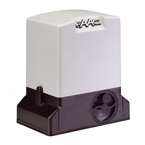
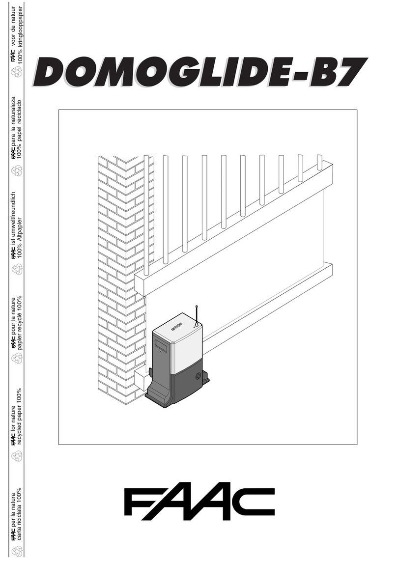
FAAC DOMOGLIDE-B7 User manual

19
EC DECLARATION OF CONFORMITY FOR MACHINES
(DIRECTIVE 98/37/EC)
Manufacturer: FAAC S.p.A.
Address: Via Benini, 1 - 40069 Zola Predosa BOLOGNA - ITALY
Declares that: DOMOGLIDE-B7 mod. operator
• is built to be integrated into a machine or to be assembled with other machinery to create a machine under the
provisions of Directive 98/37/EC;
• conforms to the essential safety requirements of the following EEC directives:
73/23/EEC and subsequent amendment 93/68/EEC.
89/336/EEC and subsequent amendment 92/31/EEC and 93/68/EEC
and also declares that it is prohibited to put into service the machinery until the machine in which it will be integrated or of
which it will become a component has been identified and declared as conforming to the conditions of Directive 98/37/
EC.
Bologna, 01-07-2005
The Managing Director
A. Bassi
WARNINGS FOR THE INSTALLER
GENERAL SAFETY OBLIGATIONS
1) ATTENTION! To ensure the safety of people, it is important that you read
all the following instructions. Incorrect installation or incorrect use of the
product could cause serious harm to people.
2) Carefully read the instructions before beginning to install the product.
3) Do not leave packing materials (plastic, polystyrene, etc.) within reach of
children as such materials are potential sources of danger.
4) Store these instructions for future reference.
5) This product was designed and built strictly for the use indicated in this
documentation. Any other use, not expressly indicated here, could compro-
mise the good condition/operation of the product and/or be a source of
danger.
6) FAAC declines all liability caused by improper use or use other than that for
which the automated system was intended.
7) Do not install the equipment in an explosive atmosphere: the presence of
inflammable gas or fumes is a serious danger to safety.
8) The mechanical parts must conform to the provisions of Standards EN 12604
and EN 12605.
For non-EU countries, to obtain an adequate level of safety, the Standards
mentioned above must be observed, in addition to national legal regulations.
9) FAAC is not responsible for failure to observe Good Technique in the
construction of the closing elements to be motorised, or for any deformation
that may occur during use.
10) The installation must conform to Standards EN 12453 and EN 12445.
For non-EU countries, to obtain an adequate level of safety, the Standards
mentioned above must be observed, in addition to national legal regulations.
11) Before attempting any job on the system, cut out electrical power and
disconnect the batteries.
12) The mains power supply of the automated system must be fitted with an all-
pole switch with contact opening distance of 3mm or greater. Use of a 6A
thermal breaker with all-pole circuit break is recommended.
13) Make sure that a differential switch with threshold of 0.03 A is fitted upstream
of the system.
14) Make sure that the earthing system is perfectly constructed, and connect
metal parts of the means of the closure to it.
15) The automated system is supplied with an intrinsic anti-crushing safety device
consisting of a torque control. Nevertheless, its tripping threshold must be
checked as specified in the Standards indicated at point 10.
16) The safety devices (EN 12978 standard) protect any danger areas against
mechanical movement Risks, such as crushing, dragging, and shearing.
17) Use of at least one indicator-light (e.g. FAACLIGHT 12VDC) is recommended
for every system, as well as a warning sign adequately secured to the frame
structure, in addition to the devices mentioned at point “16”.
18) FAAC declines all liability as concerns safety and efficient operation of the
automated system, if system components not produced by FAAC are used.
19) For maintenance, strictly use original parts by FAAC.
20) Do not in any way modify the components of the automated system.
21) The installer shall supply all information concerning manual operation of the
system in case of an emergency, and shall hand over to the user the warnings
handbook supplied with the product.
22) Do not allow children or adults to stay near the product while it is operating.
23) Keep remote controls or other pulse generators away from children, to
prevent the automated system from being activated involuntarily.
24) Transit is permitted only when the automated system is idle.
25) The user must not attempt any kind of repair or direct action whatever and
contact qualified personnel only.
26) Do not short-circuit the poles of the batteries and do not try to recharge the
batteries with power supply units other than those provided with the
equipment.
27) Do not throw exhausted batteries into containers for other waste but dispose
of them in the appropriate containers to enable them to be recycled. Disposal
costs have already been paid for by the manufacturer.
28) Maintenance: check at least every 6 months the efficiency of the system,
particularly the efficiency of the safety devices (including, where foreseen,
the operator thrust force) and of the release devices.
29) Anything not expressly specified in these instructions is not permitted.

20
Notes on DOMOGLIDE-B7 work batteries
The battery supplied with the DOMOGLIDE-B7 operator is a WORK BATTERY which directly powers the automated system. It is not a
back-upbattery.
The battery is recharged by the control board to which it is connected via a transformer and a specific integrated circuit. Bear in
mindthatittakesabout10to20minutesofrechargingtorecoverthe energy used during an opening/closing cycle (this valuevaries
according to operating ambient temperature, battery life and type of system).
Atinstallation, the batteries, due to storage, may not befully charged and thus enable the gate to operateonly a few times before
dischargingcompletely. That is why, before installinganew system, we recommend tofullychargethe supplied batteries, or provide
at least two identical fully charged batteries. In this way, you will be able to carry out the system programming operations and run
the functional checks.
HOW TO CHARGE THE BATTERIES FOR THE FIRST TIME
Charging can be done directly at the bench before the system is installed. Follow the instructions referring to the figure below:
1) connect the secondary winding of the 12Vac transformer (supplied separately) to connector J2 of the board and the primary
winding to mains voltage;
Note: if not using the transformer supplied by FAAC, make sure that the secondary winding is 12Vac - 16VA.
2) connect the battery to the J4 connector on the board and allow it to charge for about 12 hours.
NOTE: While the batteries are being charged, LED P of the board (see Fig. 19 and para. 8.2) may change from fast flashing light (a
flash about every 250msec means the battery is discharged) to steady light (battery charged).Even if the LED stays lighted steady
a little while after you start charging, leave the batteries connected for the whole of the indicated time.

21
DOMOGLIDE-B7 automated system
These instructions apply to the following model:
FAACDOMOGLIDE-B7
The DOMOGLIDE-B7 automated system automates residential
slidinggateswithleavesof upto 5m inlength and300 kgin weight.
It consists of non-reversing electro-mechanical gearmotor,
powered by a 12 Vdc work battery coupled to a control board
recharging the battery. The board can be programmed and is
used to set the following: function logics, work times (by self-
learning) and pause times, leaf speed, anti-crushing sensitivity,
and partial opening width.
Thenon-reversing system guaranteesthegate will automatically
lock when the motor is not operating. A release system enables
the gate to be moved by hand in case of malfunction.
The DOMOGLIDE-B7 automated system was designed and built
for controlling vehicle access. Do not use for any other
purpose.
1. DESCRIPTION AND TECHNICAL SPECIFICATIONS
Tab. 1 - Technical specifications of DOMOGLIDE-B7 operator
M
ledo
7B-EDILGOMOD
ylppusrewoP )yrettabyb(cdV21
)W(rewopdebrosbadetaR 84
).nim/m(deepseerf-daolraenilxaM 51
)N(ecrofcitatS 051
y
rettabdegrahcnoselcycevitucesnoC 03~
)1(
emitegrahceryrettaB elcycdetelpmochcaerof'01~
)C°(erutarepmettneibmagnitarepO 55+÷02-
)gK(thgiewrotarepO 3
,5
ssalcnoitcetorP 44PI
)m(htgnelxamfaeL 5
)gk(thgiewxamfaeL 003
)mm(DxHxLsnoisnemidllarevorotarepO 2.giFees
(1) The consecutive cycles could be reduced by over 50% at low
temperatures(< 0°C).
2. DIMENSIONS
햲햲
햲
햲햲 rotarepo7B-EDILGOMOD
햳햳
햳
햳햳 slenapedisevitcetorP
햴햴
햴
햴햴 noiniP
햵햵
햵
햵햵 esaelerlaunaM
햶햶
햶
햶햶 etalpnoitadnuoF
햷햷
햷
햷햷 draoblortnoC
햸햸
햸
햸햸 draoblortnoCdnayrettaB
햹햹
햹
햹햹 yrettabkroW
햺햺
햺
햺햺 sdraugdnaH
햻햻
햻
햻햻 )lanoitpO(annetnA
)yleta
rapesdeilppuS(remrofsnarT
•Dimensionsinmm
Fig. 1 Fig. 2

22
2 x 0,5 3 x 0,5
3 x 0,5
2 x 0,75
3 x 0,5
3. DESCRIPTION OF SYSTEM - ELECTRICAL EQUIPMENT
(standard system)
Notes:
1) To lay electric cables, use adequate rigid and/or flexible tubes.
2) To avoid any kind of interference always separate low voltage connection cables from 230Vac power cables.
3) The transformer can be remotely located up to a distance of 100 m from the unit.
12Vdcflashinglamp Receiver
Closingstop
Upper track
Key operated push-
button
Txphotocell RxPhotocell
Openingstop DOMOGLIDE-B7
operator
Differentialthermal
breaker
3 x 1.5 (2 + T) for 230Vac or 2 x
0.75for12Vac(Remote
transformer)
Fig. 3
Fig. 4

23
4. INSTALLING THE AUTOMATED SYSTEM
4.1. Preliminary checks
Toensure safetyandan efficientlyoperatingautomated system,
make sure the following conditions are observed:
• The structure of the gate must be suitable for being
automated. In particular, check that the structure is
sufficiently strong and rigid, and that its dimensions and
weight conform to those indicated in the technical
specifications.
• Make sure that the gate slides without any inclination.
• Make sure that the gate moves uniformly and correctly,
without any irregular friction during its entire travel.
• The soil must permit sufficient stability for the expansion plugs
securing the foundation plate.
• Check if the upper guide and travel limit mechanical stops
are installed.
• Remove any locks and lock bolts.
We advise you to have any metalwork carried out before the
automated system is installed.
4.2. Preparing the fundation plate
• Fit the 4 supplied caged nuts, as shown in Fig. 5, in the 4
square holes of the plate.
4.3. Securing the foundation plate
1) The foundation plate must be located as shown in Fig. 6
(right closing) or Fig. 7 (left closing) to ensure the rack and
pinion mesh correctly.
2) Secure the foundation plate to the floor, using adequate
expansion plugs (Fig. 8) and provide one or more sheaths for
routing the electric cables through the plate (Figs . 6-7 Ref.
a). Using a spirit level, check if the plate is perfectly horizontal.
Closingdir.
*Usethe dimensions according to type of rack
Galvanisedrack30x6=36.5mm
Galvanisedrack30x12=39.5mm
Nylonrack 30x20 = 41.5mm
Closingdir.
*Usethe dimensions according to type of rack
Galvanisedrack30x6=36.5mm
Galvanisedrack30x12=39.5mm
Nylonrack 30x20 = 41.5mm
Fig. 5
Fig. 7
Fig. 6
Fig. 8

24
4.4. Positioning the operator
• Lay the electric cables for connection to the accessories and
power supply as shown in Fig. 4. To facilitate making the
connections, allow the cables to project by the required
length for connection to the terminal board, transformer and
decoding card (if provided).
• Position the operator on the plate, using the supplied screws
as shown in Fig. 9.
4.5. Adjusting the operator
• Adjust the distance of the operator from the gate by referring
to Fig. 10.
4.6. Securing the operator
• Temporarily fix the operator by slightly tightening the screws
as shown in Fig. 11.
4.7. Releasing the operator
Preparetheoperator for manual operating mode as described
below:
• Open the protective door with a coin.
• Take the supplied key located inside the door, fit it in the
release system and turn it clockwise until it reaches the
mechanical stop (Fig. 12).
Usethe dimensions according to typeofrack:
Galvanisedrack30x6 ⇒A=46.5mmandB=146mm
Galvanisedrack30x12 ⇒A=49.5mmandB=146mm
Nylon rack 30x20 ⇒A=51.5mmandB=112.5mm
Fig. 9
Fig. 10
Fig. 11
Fig. 12

25
4.8. Installing the rack
4.8.1. Steel rack to be welded (Fig. 13)
1) Place the three threaded pawls on the rack element, positioning them at the top of the slot. In this
way, the slot play will enable any adjustments to be made.
2) Manually take the gate into its closing position.
3) Lay the first piece of rack at appropriate level on the pinion and weld the threaded pawl on the
gate as shown in Fig. 16.
4) Move the gate manually, checking if the rack is resting on the pinion, and weld the second and
third pawl.
5) Bring another rack element near to the previous one, using a piece of rack (as shown in Fig. 17) to
synchronise the teeth of the two elements.
6) Move the gate manually and weld the three threaded pawls, so proceeding until the gate is fully
covered.
4.8.2. Steel rack to be screwed (Fig. 14)
1) Manually take the gate into its closing position.
2) Lay the first piece of rack at the appropriate level on the pinion and place the spacer between
rack and gate, positioning it at the top of the slot.
3) Mark the hole position on the gate. Drill a Ø 6.5 mm hole and thread with a Ø 8 mm tap. Screw the
bolt.
4) Move the gate manually, checking if the rack is resting on the pinion, and repeat the operations
at point 3.
5) Bring another rack element near to the previous one, using a piece of rack (as shown in Fig. 17) to
synchronise the teeth of the two elements.
6) Move the gate manually and carry out the securing operations as for the first element, proceeding
until the gate is fully covered.
4.8.3. Nylon rack to be screwed (Fig. 15)
1) Manually take the gate into its closing position.
2) Lay on the pinion the first piece of rack at the appropriate level and mark the hole position on the
gate; make a hole with a 4 mm bit and screw the 6x20 mm self-tapping screw with reinforcing
plate.
3) Move the gate manually, checking if the rack is resting on the pinion, and repeat the operations
at point 2.
4) Bring another rack element near to the previous one, using a piece of rack (as shown in Fig. 17) to
synchronise the teeth of the two elements.
5) Move the gate manually and carry out the securing operations as for the first element, proceeding
until the gate is fully covered.
Fig. 13
Fig. 14
Fig. 15
Fig. 17Fig. 16

26
Notes on rack installation
• Make sure that, during the gate travel, all the rack elements
mesh correctly with the pinion.
• Do not, on any account, weld the rack elements either to
the spacers or to each other.
• When you have finished installing the rack, adjust the distance
between the pinion teeth and the rack groove, checking if
the distance is 2.5 mm (Fig. 18) along the entire travel, using
the rack slots.
• Manually check if the gate habitually reaches the travel limit
mechanical stops and make sure that there is no friction
during gate travel.
• Do not use grease or other lubricants between rack and
pinion.
Fig. 18

27
J2
J1
J5
J4
F1
PP1
P2
LED
J3
J10
CONTROL BOARD
WARNINGS
Attention: Before attempting any job on the control board (connections, maintenance), cut out electric power and the battery.
- Install, upstream of the system, a differential thermal breaker with adequate tripping threshold.
- Always separate 230VAC power cable from control and safety cables (push-buttons, receiver, photocells, etc.). To avoid any
electric noise, use separate sheaths or a shielded cable (with earthed shield).
5. BOARD LAYOUT
6. CONTROL BOARD TECHNICAL SPECIFICATIONS
Tab. 2 - Technical specifications
DEL sDELgnimmargorP
PDELscitsongaiddnaNOrewoP
1P nottub-hsupgnimmargorp"noitcnuF"
2P nottub-hsupgnimmargorp
"eulaV"
1F A02FesufrotomdnayrettaB
1J draoblanimreTseirosseccA
2J draoblanimreTremrofsnarT
3J draoblanimretno
itcennocrotoM
4J rotcennocyrettaB
5J rotcennocrevieceRPR/cediniM
01J draoblanimretrosnescitengaM
ylppusrewoP caV21
seirettaB 59x56x051snoisnemid-hA7cdV21bPcitemreH
scitsiretcarahcremrofsnarT AV61-caV21yr
adnoceS-zH06/05~caV032yramirP
tnerrucxamrotoM A51
erutarepmettneibmagnitarepO C°55+÷C°02-
sesufnoitcetorP A
02-1°N
noitcnufgnihsurc-itnA lortnoctnerruC/redocnE
cdV42tadaol.xamseirosseccA Am051
daolxamrotcennocdipaR Am05
scigolnoitcnuF citamotua-imeS/ecivedytefaS/citamotua"deppetS"/citamotuA
emitgnisolc/gninepO gninrael
-flesyB
emitesuaP .ces03,02,01,5:elbammargorP
htdiwgninepolaitraP .mc081,051,021,09
deepS slevel4noelbatcel
eS
tnemtsujdaecrofcitatS slevel4noelbatceleS
noitareleceD cinortcelE
stupnidraoblanimreT rosneS-.gnslctasec
ivedytefaS-.gnpotasecivedytefaS-potS-nepOyllaitraP-nepO
stuptuodraoblanimreT ylppusrewopcdV21-cdV42seir
osseccA-thgil-rotacidni-pmalgnihsalF-rotoM
srotcennoC yrettaB-sdracPR-sdraccediniM
snoitcnufelbammargorP deepsrotarepo-ecrofgnihsurc-itna-htdiwgninepolaitrap-emitesuap-cigoL
Jumpersposition
must not be modified
Fig. 19

28
**
*
7. ELECTRICAL CONNECTIONS
Wire up as shown in Fig. 20
7.1. Description of J1 terminal board
Tab. 3 -Description of accessories connection
lanimreT
noitpircseD yrosseccadetcennoC
1ANEPO)dnammocgninepolatot( )nottub-hsupdetarepoyek.g.e(tcatnocANhtiweciveD
2BNEPO)dnammocgninepolaitrap( )nottub-hsupdetarepoyek.g.e(tcatnocANhtiweciveD
3POTS)dnammockcoletag( .tcatnocCNhtiwe
civeD
)1(
4POWSF)tcatnocsecivedytefasgninepo( )MAEBEFAS.g.e(sllecotohP
)1(
5LCWSF)tcatnocsecivedytefasgnisolc( )MAEBEFAS.g.e(sllecotohP
)1(
6DESUTON/
8-7 +)ylppusrewopV42rofevitisop( Am051fonoitprosbalatotXAMseirosseccA
11-9 .L.W)thgilrotacidniotylp
pusrewop( pmalW5.0-V21
11-01 PMAL)pmalgnihsalfotylppusrewop( pmalgnihsalfV21THGILCAAF
51÷21 -)ylppusrewopcdV4
2rofevitagen( /
(1) If you are not using any accessories, connect the terminal to earth (terminals 12 ÷ 15).
Note: when the automated system is idle, the power supply (+24 V) to accessories is disabled.
Magnetic
sensor
* If not using the transformer supplied by FAAC, make sure that the secondary
winding is 12Vac - 16VA.
** For connection of photocells, see par. 7.4
Fig. 20

29
7.2. Wiring the motor
Wire the DOMOGLIDE-B7 motor according to the gate closing direction as shown in the figure below.
7.4. Connection of photocells and safety devices
Before connecting the photocells (or other devices) we advise
youtoselectthetypeof operation according to the movement
area to be protected (see Fig. 22). N.B.: If two devices with N.C. contact have the same function,
they must be connected to each other in series (Fig. 23).
N.B.: If two devices with N.A. contact have the same function,
they must be connected to each other in parallel (Fig. 24).
Battery
ClosingDir.
BLUE
BROWN
Battery
ClosingDir.
BROWN
BLUE
Closing safety devices Openingor opening/closing
safety devices
Opening safety devices
Connectionof2 NC contacts in series
Connectionof 2 NA contacts inparallel
Fig. 21
Fig. 23
Fig. 24
Fig. 22

30
Attention: a maximum of 2 pairs of SAFEBEAM photocells can be connected to the control board
Examples of photocell connections
7.5. Connection of MINIDEC, RP cards
Insert the MINIDEC decoding card or RP card in the block
connector J5 (Fig. 19) as indicated in Fig. 26 showing the
connection of a MINIDEC card.
For programming the decoding cards, consult the individual
instructions.
8. START-UP
8.1. Powering up the system
After making allthe cable connectionswedescribed previously,
power up the system to enable diagnostics, positioning of the
travel limit magnets, check of inputs status and programming.
8.2. Diagnostics
LED"P" (seeFig.19) -visible from insidetheenclosure -performs the
diagnosticsfunction. The LED has 4 statuses as showninthetable
below:
Tab. 4 - LED P status description
thgilydaetS.degrahcyrettabdnatneserprewopsniaM
gnihsalfwolS
yrevesthgil(
)dnoces
eromtonrofdeilppustonrewo
psniaM
.degrahcyrettabhtiw,setunim5naht
syatsDELeht,snruterrewopsniamnehW
.ylidaetsdethgil
DELeht,deilppu
stonllitssirewopsniamfI
.)edomPEELS(ffoseog
gnihsalfdipaR
052yrevesthgil(
)cesm
yrettabdnatneserprewopsnia
M
.)dekcoletag(degrahcsid
ehtlitnuyldiparhsalfotseunitnocDELehT
.yltneiciffusdegrahcersahyrettab
seogDELe
ht,deilppustonsirewopsniamfI
.)edomPEELS(ffo
FFOthgiL.)edomPEELS(deilppusrewopsniamoN
Note: in the SLEEP mode, an OPEN pulse is sufficient to move
the gate (with charged battery)
1 pair of CLOSING photocells connection of no devices 1 pair of OPENING photocells
2 pairs of CLOSING photocells 1 pair of CLOSING photocells and 1
pair of OPENING/CLOSING photocells
Fig. 25
Fig. 26

31
햲햳햴
!
8.3. Positioning the travel limit magnets
8.3.1. Prearrangement
TheDOMOGLIDE-B7operatorissuppliedwithasensorwhich, by
detecting the transit of two magnets secured to the top of the
rack, commands the gate to stop when closing or opening.
Procedure for correct positioning of the two supplied magnets:
• Assemble the magnets according to the type of rack used:
1) Galvanised rack 30x6 module 4 (Fig. 27 - Ref. 햲햲
햲햲
햲)
2) Galvanised rack 30x12 module 4 (Fig. 27 - Ref. 햳햳
햳햳
햳)
3) Reinforced nylon rack 30x20 module 4 (Fig. 27 - Ref. 햴햴
햴햴
햴)
8.3.2. Positioning
• Position the magnets on the rack as shown in Fig. 28 Ref 햲햲
햲햲
햲.
Make sure that distance between the magnet and the
operator's body is 5mm max (Fig. 28 Ref. 햳햳
햳햳
햳).
• Fully tighten the operator fixing screws(Fig. 11).
8.3.3. Adjustment and Fixing
• Press push-button P2 (Fig. 29 and par. 8.4) to enter the inputs
status function.
• Manually take the gate to opening position, but allow a
space of 2 cm from the travel limit mechanical stop.
• Slide the magnet on the rack (Fig. 30) until you see that LED1
on the control board goes off (Fig. 29).
• Tighten the magnet's securing screws.
• Manually take the gate to closing position, but allow a space
of 2 cm from the travel limit mechanical stop.
• Slide the magnet on the rack (Fig. 31) until you see that LED1
on the control board goes off (Fig. 29).
• Tighten the magnet's securing screws.
8.3.4. Operator locked
• Make sure the gate is in its closed position.
• Turn the release key anti-clockwise (Fig. 32).
• Remove the release key and put it back in its place; close
the protective door.
• Move the gate until the release meshes.
led1
Fig. 27
Fig. 28
Fig. 29
Fig. 31
Fig. 30
Fig. 32

32
P1
P2
P1
P2
!
!
P1
P2
P1
P2
!
!
P1
P2
!
!
!
!
!
P1
P2
P1
P2
!
!
!
!
8.4. Status of inputs
Theboardhasa function for checking the status of inputs on the
terminalboard.
In all LEDS OFF status (LEDs both with letters and numbers), press
the P2 push-button.
When the LEDs light up, this indicates the inputs status as shown
in Tab. 5.
Tab. 5 - Description of inputs status LEDs
deL dethgiL
)tcatnocdesolc(
ffO
)tcatnocnepo(
A= AnepO evitcadnammoC evitcanidnammoC
B= BnepO evitcadnammoC evitcanidnammoC
C= potS evitcanidnammoC evitcadnammoC
D= pow
sF secivedytefaS
degagnesid
secivedytefaS
degagne
E= lcwsF secivedytefaS
degagnesid
secivedytefaS
degagne
1= erosneS d
egagnesidrosneS degagnerosneS
Notes:
• The status of LEDs with the gate closed at rest is shown in bold.
• In the inputs status function, push-button P1 commands an
OPEN A.
Whencheckshave finished, once again press push-button P2 to
exit the inputs status function.
8.5. Programming
These are the basic settings of the board:
Function logic: A4
Pause times: B1
Partial opening width: C2
Static force: D3
Speed: E3
If you wish to execute customised programming (see par. from
8.5.1 to 8.5.5) and time-learning (see par.8.5.6) follow the steps
in the next pages.
8.5.1. Function Logic
In all LEDS OFF status, press push-
button P1.
Led A will light up together with LED
4.
Presspush-button P2, forachoice of
4differentfunctionlogics.
A1 automatic
A2 safety
A3 Step-by-step automatic
A4 Step-by-step semi-
automatic (default)
8.5.2. Pause Times
Presspush-buttonP1 again and LED
B will light together with LED 1.
Presspush-button P2, forachoice of
4differentpausetimes.
B1 5 seconds (default)
B2 10 seconds
B3 20 seconds
B4 30 seconds
8.5.3. Partial Opening Width
Presspush-buttonP1 again and LED
C will light together with LED 2.
Presspush-button P2, forachoice of
4 different partial openings.
C1 90 cm
C2 120 cm (default)
C3 150 cm
C4 180 cm

33
P1
P2
P1
P2
!
!
P1
P2
P1
P2
!
!
P1
P2
P1
P2
P1
P2
!
!
!
!
!
!
!
8.5.4. Static Force
Presspush-button P1 again and LED
D will light together with LED 3.
Presspush-button P2, forachoice of
4differentstaticforces.
D1 low
D2 medium low
D3 medium high (default)
D4 high
8.5.5. Speed
Presspush-button P1 again and LED
E will light together with LED 3
Presspush-button P2, forachoice of
4different speeds
E1 low
E2 medium low
E3 medium high (default)
E4 high
8.5.6. Simple learning
Ifyou press push-button P1 again,
all 5 LEDs from A to E will light.
(Makesurethatthegateisclosed
and operator locked)
If you press push-button P2 for 1
second,thegatewillstartmoving
until the opening travel limit
magnet engages the sensor on
theoperator.The5LEDsflashduring
this stage.
After learning has been
completed, the 5 LEDs remain
lighted steadily.
Presspush-button P1 again to exit
(all LEDs OFF). Give an OPEN A
pulse with the radio control or the
keypush-button toclosethe gate.
8.6. Status of indicator light
If you wish to use a 12V-0.5W indicator light (terminal 9 - 11 of J1,
seeFig. 20),thefollowing table showsthe statuses oftheindicator
light according to gate position.
Tab. 6 - Statuses of indicator light
8.7. Testing the automated system
After programming, run an accurate functional check of the
automated system and of all the accessories connected to it,
especially the safety devices.
sutatsthgil-rotacidnI sutatsetaG
ffOthgiLdesolC
dethgiLesuapninepO-nepO
gnihsalFgnisolC
dethgiLgninepO
dethgiLdekcoL

34
○○○○○○○○○○○○○○○○○○○○○○○○○○○○○○○○
○○○○○○○○○○○○○○○○○○○○○○○○○○○○○○○○
○○○○○○○○○○○○○○○○○○○○○○○○○○○○○○○○
○○○○○○○○○○○○○○○○○○○○○○○○○○○○○○○○
○○○○○○○○○○○○○○○○○○○○○○○○○○○○○○○○
○○○○○○○○○○○○○○○○○○○○○○○○○○○○○○○○
○○○○○○○○○○○○○○○○○○○○○○○○○○○○○○○○
○○○○○○○○○○○○○○○○○○○○○○○○○○○○○○○○
○○○○○○○○○○○○○○○○○○○○○○○○○○○○○○○○
○○○○○○○○○○○○○○○○○○○○○○○○○○○○○○○○
○○○○○○○○○○○○○○○○○○○○○○○○○○○○○○○○
○○○○○○○○○○○○○○○○○○○○○○○○○○○○○○○○
○○○○○○○○○○○○○○○○○○○○○○○○○○○○○○○○
○○○○○○○○○○○○○○○○○○○○○○○○○○○○○○○○
○○○○○○○○○○○○○○○○○○○○○○○○○○○○○○○○
○○○○○○○○○○○○○○○○○○○○○○○○○○○○○○○○
○○○○○○○○○○○○○○○○○○○○○○○○○○○○○○○○
○○○○○○○○○○○○○○○○○○○○○○○○○○○○○○○○
○○○○○○○○○○○○○○○○○○○○○○○○○○○○○○○○
○○○○○○○○○○○○○○○○○○○○○○○○○○○○○○○○
○○○○○○○○○○○○○○○○○○○○○○○○○○○○○○○○
○○○○○○○○○○○○○○○○○○○○○○○○○○○○○○○○
○○○○○○○○○○○○○○○○○○○○○○○○○○○○○○○○
○○○○○○○○○○○○○○○○○○○○○○○○○○○○○○○○
○○○○○○○○○○○○○○○○○○○○○○○○○○○○○○○○
○○○○○○○○○○○○○○○○○○○○○○○○○○○○○○○○
○○○○○○○○○○○○○○○○○○○○○○○○○○○○○○○○
○○○○○○○○○○○○○○○○○○○○○○○○○○○○○○○○
○○○○○○○○○○○○○○○○○○○○○○○○○○○○○○○○
○○○○○○○○○○○○○○○○○○○○○○○○○○○○○○○○
○○○○○○○○○○○○○○○○○○○○○○○○○○○○○○○○
○○○○○○○○○○○○○○○○○○○○○○○○○○○○○○○○
○○○○○○○○○○○○○○○○○○○○○○○○○○○○○○○○
○○○○○○○○○○○○○○○○○○○○○○○○○○○○○○○○
○○○○○○○○○○○○○○○○○○○○○○○○○○○○○○○○
○○○○○○○○○○○○○○○○○○○○○○○○○○○○○○○○
○○○○○○○○○○○○○○○○○○○○○○○○○○○○○○○○
○○○○○○○○○○○○○○○○○○○○○○○○○○○○○○○○
○○○○○○○○○○○○○○○○○○○○○○○○○○○○○○○○
○○○○○○○○○○○○○○○○○○○○○○○○○○○○○○○○
○○○○○○○○○○○○○○○○○○○○○○○○○○○○○○○○
○○○○○○○○○○○○○○○○○○○○○○○○○○○○○○○○
○○○○○○○○○○○○○○○○○○○○○○○○○○○○○○○○
○○○○○○○○○○○○○○○○○○○○○○○○○○○○○○○○
○○○○○○○○○○○○○○○○○○○○○○○○○○○○○○○○
○○○○○○○○○○○○○○○○○○○○○○○○○○○○○○○○
○○○○○○○○○○○○○○○○○○○○○○○○○○○○○○○○
○○○○○○○○○○○○○○○○○○○○○○○○○○○○○○○○
○○○○○○○○○○○○○○○○○○○○○○○○○○○○○○○○
○○○○○○○○○○○○○○○○○○○○○○○○○○○○○○○○
○○○○○○○○○○○○○○○○○○○○○○○○○○○○○○○○
○○○○○○○○○○○○○○○○○○○○○○○○○○○○○○○○
○○○○○○○○○○○○○○○○○○○○○○○○○○○○○○○○
○○○○○○○○○○○○○○○○○○○○○○○○○○○○○○○○
○○○○○○○○○○○○○○○○○○○○○○○○○○○○○○○○
○○○○○○○○○○○○○○○○○○○○○○○○○○○○○○○○
○○○○○○○○○○○○○○○○○○○○○○○○○○○○○○○○
○○○○○○○○○○○○○○○○○○○○○○○○○○○○○○○○
○○○○○○○○○○○○○○○○○○○○○○○○○○○○○○○○
○○○○○○○○○○○○○○○○○○○○○○○○○○○○○○○○
○○○○○○○○○○○○○○○○○○○○○○○○○○○○○○○○
○○○○○○○○○○○○○○○○○○○○○○○○○○○○○○○○
○○○○○○○○○○○○○○○○○○○○○○○○○○○○○○○○
○○○○○○○○○○○○○○○○○○○○○○○○○○○○○○○○
○○○○○○○○○○○○○○○○○○○○○○○○○○○○○○○○
○○○○○○○○○○○○○○○○○○○○○○○○○○○○○○○○
○○○○○○○○○○○○○○○○○○○○○○○○○○○○○○○○
○○○○○○○○○○○○○○○○○○○○○○○○○○○○○○○○
○○○○○○○○○○○○○○○○○○○○○○○○○○○○○○○○
○○○○○○○○○○○○○○○○○○○○○○○○○○○○○○○○
○○○○○○○○○○○○○○○○○○○○○○○○○○○○○○○○
○○○○○○○○○○○○○○○○○○○○○○○○○○○○○○○○
○○○○○○○○○○○○○○○○○○○○○○○○○○○○○○○○
○○○○○○○○○○○○○○○○○○○○○○○○○○○○○○○○
○○○○○○○○○○○○○○○○○○○○○○○○○○○○○○○○
9. MANUAL OPERATION
If the gate has to be moved manually due to a malfunction of
the automated system, use the release device as follows:
• Open the protective door with a coin.
• Take the supplied key located inside the door, fit it in the
release system and turn it clockwise until it reaches the
mechanical stop (fig. 33).
• Open or close the gate manually.
10. RESTORING NORMAL OPERATION MODE
Procedure to relock the gate:
• Manually take the gate back to its closed position.
• Turn the release key anti-clockwise until it reaches the
mechanical stop (Fig. 33).
• Remove the release key and put it back in its place; close
the protective door.
• Move the gate until the release meshes.
11. MAINTENANCE
Carry out the following jobs at least every 6 months:
• Check if the anti-crushing facility is correctly set.
• Check the efficiency of the release system.
• Check the efficiency of the safety devices and accessories.
12. REPAIRS
For any repairs, contact authorised Repair Centres.
13. NOTES
LOCKS
RELEASES
Fig. 33

35
a/7.baT
"1A"ACIGOL SESLUP
SUTATSETAGA-NEPOBNEPOPOTSSECIVEDYTEFASGNINEPOSECIVEDYTEFASGNISOLCECIVEDYTEFASLC/PO
DE
SOLC emitesuapretfasesolc-erdnasev/faelsnepO )delbasidNEPO(tceffeoNtceffeoN)delbasidNEPO(tceffeoN
ESUAPnoN
EPO emitesuapsdaoleR
noitarepospotS
tceffeoNemitesuapsdaoleR
GNISOLC yletaidemmisev/faelehtsnepo-eR tceffeoN otsesreveryletaidemmI
nepo
,esaelerno,dnaskcoL
gninepotasesrever
GNINEPO tceffeoN otsesreveryletaidemmI
esol
ctceffeoN ,esaelerno,dnaskcoL
gnineposeunitnoc
DEKCOL sev/faelehtsesolCtceffeoNtceffeoN)delbasidNEPO(tceffeo
N
b/7.baT
"2A"ACIGOL SESLUP
SUTATSETAGA-NEPOBNEPOPOTSSECIVEDYTEFASGNINEPOSECIVEDYTEFASGNISOLCECIVEDYTEFASLC/PO
DE
SOLC emitesuapretfasesolc-erdnasev/faelsnepO )delbasidNEPO(tceffeoNtceffeoN)delbasidNEPO(tceffeoN
ESUAPnoN
EPO yletaidemmisev/faelehtsesolc-eR
noitarepospotS
tceffeoN ongepmisidla)otibiniNEPO("5opodeduihC
GNISOLC y
letaidemmisev/faelehtsnepo-eR tceffeoN otsesreveryletaidemmI
nepo
,esaelerno,dnaskcoL
gninepotasesrever
GNI
NEPO yletaidemmisev/faelehtsesolc-eR otsesreveryletaidemmI
esolc tceffeoN ,esaelerno,dnaskcoL
gnineposeunit
noc
DEKCOL sev/faelehtsesolCtceffeoNtceffeoN)delbasidNEPO(tceffeoN
c/7.baT
"3A"ACIGOL SESLUP
SUTATSETAGA-NEPOBNEPOPOTSSECIVEDYTEFASGNINEPOSECIVEDYTEFASGNISOLCECIVEDYTEFASLC/PO
DE
SOLC emitesuapretfasesolc-erdnasev/faelsnepO )delbasidNEPO(tceffeoNtceffeoN)delbasidNEPO(tceffeoN
ESUAPnoN
EPO noitarepospotS
noitarepospotS
tceffeoNemitesuapsdaoleR
GNISOLC yletaidemmisev/faelehtsnepo-eR tceffeoN ot
sesreveryletaidemmI
nepo
,esaelerno,dnaskcoL
gninepotasesrever
GNINEPO noitarepospotS otsesreveryletaidemmI
esolc tceffeoN ,esaelerno,dnaskcoL
gnineposeunitnoc
DEKCOL sev/faelehtsesolCtceffeoNtceffeoN)delbasidNEPO(tce
ffeoN
d/7.baT
"4A"ACIGOL SESLUP
SUTATSETAGA-NEPOBNEPOPOTSSECIVEDYTEFASGNINEPOSECIVEDYTEFASGNISOLCECIVEDYTEFASLC/PO
DE
SOLC sev/faelsnepO )delbasidNEPO(tceffeoNtceffeoN)delbasidNEPO(tceffeoN
NEPO yletaidemmisev/faelehtsesolc-e
R
noitarepospotS
tceffeoN
)delbasidNEPO(tceffeoN
GNISOLC noitarepospotS otsesreveryletaidemmI
nepo
,esaelerno
,dnaskcoL
gninepotasesrever
GNINEPO noitarepospotS otsesreveryletaidemmI
esolc tceffeoN ,esaelerno,dnaskcoL
g
nineposeunitnoc
DEKCOL noitceridesrevernignivomstratseR:NEPOretfA
yletaidemmisev/faelehtsesolc-eR:POTSre
tfA )delbasidNEPO(tceffeoN ti,nepotsumtifi(tceffeoN
)NEPOselbasid )delbasidNEPO(tceffeoN

36
TROUBLESHOOTING
tluaF sesuacelbissoP noituloS
FFOPDELdraoB
5nahteromrofdeilppusrewopsniamoN
degrahcyrettabhtiwsetunim .etagehtevomoteslupNEPOnaevigtsu
J
yrettabhtiwdeilppusrewopsniamoN
degrahcsid
rewopsniamlitnudekcolyatslliwetagehT
yltneiciffussiyrettabeh
tdnasnruter
.degrahcer
tonseodtI.nwodtuhsmetsysdetamotuA
rolortnocoidar(dnammocynaybevom
.)hctiwsrotceles
detarepoyek
seirettabdegrahcsiD
roFFOsidraobehtfoPDELfikcehC
ehtwolla,esacrettalehtnI.yldipargnihsalf
.eg
rahcerotseirettab
tonslanimret)5dna4(WSFdna)3(POTS
.detcennoc
ehtninwohssagniriwehtkcehC
dnaD,CsDELfikceh
cosladnasnoitcurtsni
.sutatsstupniehtnoyltcerrocthgilE
.deliafesufdraoB ,yrassecenfi,dna)A02F(esufehtkce
hC
.tiecalper
ylnosevoM.nwodtuhsmetsysdetamotuA
.dnammocdetarepo-yekyb
42nahteromrofdeilppusrewopsniamoN
.
sruoh
nehwdetavitca-ersirevieceroidarehT
eslupagnivigybrosnruterrewopsniam
sihtni;hctiwsrotcelesdetarepo
-yekehthtiw
nihtiwnrutertonseodrewopsniamfi,esac
ecnosireviecereht,sruoh42txeneht
.nwodderewopniaga
lortn
ocoidarytluaF
ehtfikcehc,lortnocoidarrehtonagnisU
fi,dnayltcerrocgnitareposimetsys
.lortnocoidarytluafeh
tecalper,yrassecen
draobreviecerytluaF
nwodtuhsllitssimetsysdetamotuaehtfI
sawlortnocoidartahtgnikcehcre
tfaneve
.dracreviecerehtecalper,ytluafton
rotomehT.nwodtuhsmetsysdetamotuA
.evomtonseodetagehttub,snur
ti
millevartehtdehcaersahrotomehT
.potslacinahcem
repsastengamtimillevartehtegnarrA
.snoitcurtsni
metsysdeta
motuaeht,tnemevomgniruD
.nosaeronrofnoitomsesrever
yranigaminagniteem(wolootecroF
)elcatsbo
ehtnoselcatsb
oynaeraerehtfikcehC
nevenurosenotssahcus,etagehtfoetuor
ehtfoecrofcitatsehtesaercnidna,tlahpsa
.rotom
eri
tneehtsmrofrepmetsysdetamotuaehT
tiro.noitarelecednilevartgnisolc/gninepo
tuohtiwecivedtimillevartehtno
spots
.noitarelecedgnimrofrep
.yltcerrocdetucexetongninraeL .snoitcurtsnirepsagninraeletucexE
tonsitengam
timillevartehtfonoitisopehT
.tcerroc
repsasecivedtimillevartfonoitisopkcehC
niagagninraeletucexednasnoit
curtsni
tapotslacinahcemehtsehcaeretagehT
.deepslluf
tonsitengamtimillevartehtfonoitisopehT
.tcerroc
repsa
secivedtimillevartfonoitisopkcehC
niagagninraeletucexednasnoitcurtsni

User’s guide
DOMOGLIDE-B7 AUTOMATED SYSTEM
Read the instructions carefully before using the product and
store them for future use
GENERAL SAFETY REGULATIONS
If correctly installed and used, the DOMOGLIDE-B7 automated
system ensures a high degree of safety.
Somesimple rules on behaviourcanprevent accidental trouble:
- Do not pass through the gate when it is moving. Wait for the
gate to open fully before passing through it.
- Do not, on any account, stand in the gate's movement range.
- Do not stand near the automated system or allow children,
persons or things to stand or lie there, especially while it is in
use.
- Keep remote controls or other pulse generators away from
children, to prevent the automated system from being
activated involuntarily.
- Do not allow children to play with the automated system.
- Do not willingly obstruct gate movement.
- Prevent any branches or shrubs from interfering with gate
movement.
- Keep indicator-lights efficient and easy to see.
- Do not attempt to activate the gate by hand unless you
have released it.
- In the event of malfunctions, release the gearmotor to allow
access and wait for qualified technical personnel to do the
necessary work.
- Before using the manual release, disconnect the batteries.
- Do not in any way modify the components of the automated
system.
- Do not attempt any kind of repair or direct action whatever
and contact qualified personnel only.
- At least every six months: arrange a check of the automated
system, safety devices and accessories.
DESCRIPTION
These instructions apply to the following model:
FAACDOMOGLIDE-B7
The FAAC DOMOGLIDE-B7 automated system for residential
sliding gates consists of a non-reversing electro-mechanical
operator, powered on 12 Vdc, coupled to a control board with
awork battery (not a back-upbattery),ensuringoperation even
in the event of a mains power cut.
Thenon-reversing system guarantees thegatewill automatically
lock when the motor is not operating. A release system enables
the gate to be moved by hand in case of malfunction.
Thegearmotoris controlled by an electronic control unit housed
inside the gearmotor where it is adequately protected against
atmosphericagents.
The gates is normally in its closed position.
Whenthe electronic controlunitreceives an openingcommand
viathe radio control oranyother pulse generator, itactivatesthe
gearmotorto move thegateuntil it reaches theopeningposition
toallowaccess.
Ifautomatic mode was set, theleavescloses automatically after
the selected pause time has elapsed.
Ifthe semi-automatic modewasset, a secondpulsemust be sent
to close the gate again.
A stop pulse (if supplied) always stops movement.
Fordetails on thebehaviour of theautomatedsystem in different
function logics, consult the installation Technician.
Automated systems include safety devices that prevent the
gate from moving when there is an obstacle in the area they
protect.
The DOMOGLIDE-B7 automated system is provided with an
adjustableanti-crushing device whichreverses gate movement
in case of contact with an obstacle.
The warning-light indicates that the gate is currently moving.
MANUAL OPERATION
If the gate has to be moved manually due to a fault of the
automated system, use the release device as follows:
• Open the protective door with a coin.
• Take the supplied key located inside the door, fit it in the
release system and turn it clockwise until it reaches the
mechanical stop (Fig. 1).
• Open or close the gate manually.
RESTORING NORMAL OPERATION MODE
• Manually take the gate back to its closed position.
• Turn the release key anti-clockwise until it reaches the
mechanical stop (Fig. 1).
• Remove the release key and put it back in its place; close
the protective door.
• Move the gate until the release meshes.
LOCKS
RELEASES
Fig. 1
Other manuals for DOMOGLIDE-B7
1
Table of contents
Other FAAC Garage Door Opener manuals

FAAC
FAAC 593 User manual

FAAC
FAAC 391 User manual

FAAC
FAAC Estate Swing E-SC 1102 Series User manual

FAAC
FAAC 844 ER 3PH User manual

FAAC
FAAC 531EM User manual

FAAC
FAAC D1000 User manual

FAAC
FAAC C850 User manual

FAAC
FAAC S2500I CERNIERA User manual

FAAC
FAAC 739 240V User manual

FAAC
FAAC DOMOGLIDE-B7 User manual