19
ENGLISHENGLISH
5.2. DESCRIPTION
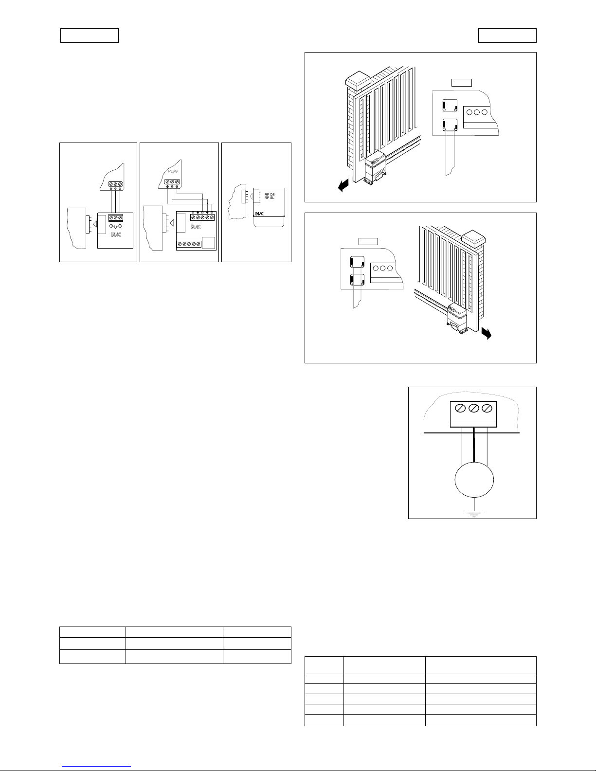
5.2.1. CONNECTOR J1
TheconnectorJ1is used for the quick connection of MINIDEC,
DECODER, RP RECEIVER boards (Figs. 25,26,27).
Accessory boards are to be inserted with their component
sides facing the inside of the 746MPS electronic control unit.
Always disconnect the power supply before inserting or
removing accessory boards.
Fig. 27
Fig. 26Fig. 25
MINIDEC
SL/DS
PLUS
844MPS
DECODER
SL/SLP/DS
844MPS
844MPS
5.2.2. TERMINAL BLOCK J2 (low voltage)
1
&
5
=Common/Negative of accessory power supply (-)
2 = OPEN control device (N.O.)
Any control device (pushbutton,detector,..) which,
on closing the contact,relays an open and/or close
impulse to the gate.
To install more than one Open control device,con-
nect the N.O.contacts in parallel.
3 = STOP control device (N.C.)
Any control device (e.g. pushbutton) which, on
opening a contact,stops the movement of the gate.
To install more than one Stop control device, con-
nect the N.C.contacts in series.
ÜIf no Stop control devices are to be connected,
place a jumper across the input and the common
terminal (terminal 1 or 5).
4 = FSW closure safety device (N.C.)
Any control device (photocells, safety edges,mag-
netic loops) with an N.C.contact which reverses the
movement of the gate when an obstacle is de-
tected within the protected area during the clos-
ing movement. If a closure safety device is tripped
when the gate is open or during a pause time, they
will prevent gate closure. These devices do not in-
tervene during gate opening movements.
To install more than one safety device,connect the
N.C.contacts in series.
ÜIf no closure safety devices are to be installed,
place a jumper across this input and the common
terminal (terminal 1or 5).
6 = 24Vdc accessories power supply positive (+)
The maximum load of the accessories is 360mA.
To calculate power draw,refer to the instructions for
the individual accessories.
7 = Warning Light output
For information regarding operation of the warning
light,refer to the table below.
Gate status
Closed Opening/Open Closing
Off On Flashing
5.2.3. CONNECTORS J3-J4 (limit switch)
J3 = Connection of limit switch for left-hand closure
J4 = Connection of limit switch for right-hand closure
Refer to Figs. 28-29 for quick connection of the inductive limit
switch sensor for the corresponding gate closure direction.
Fig. 28
Fig. 29
BROWNBLACK
BLUE
Fig. 30
5.2.4. TERMINAL BLOCK J5 (high voltage)
Terminal block for motor
connection.
Connect the wires to the
terminals of J5 as shown in
Fig.30.
B
LACK
AND
B
ROWN
WIRES
=
electric motor supply
phases
B
LUE
WIRE
= electric motor
common
5.2.5. CONNECTOR J6
(high voltage)
Connector for quick
connection of the
capacitor.
5.2.6. TERMINAL BLOCK J7 (high voltage)
230V~ terminal block for connection of the flashing light (max
60W).
5.2.7. TERMINAL BLOCK J8 (high voltage)
Terminal block for connection of the 230V~ 50Hz power supply
(L=Phase N=Neutral)
Connect the earth wire to the operator as shown in Fig.31
5.2.8. INDICATOR LEDS
5 LEDs on the board indicate the status of the terminal inputs:
L
ED
ON
= contact closed
L
ED
OFF
= contact open
TABLE 4 MEANING OF STATUS INDICATOR LEDS
LED ON OFF
OPEN
Command active Command not active
STOP
Command not active Command active
FSW
Safeties disengaged Safeties engaged
FCC
Closing limit disengaged Closing limit engaged
FCA
Opening limit disengaged Opening limit engaged
J4
J3
CH
DX
CH
SX
746MPS
J2
J4
J3
CH
DX
CH
SX
746MPS
J2
M
J5
746MPS 746MPS 746MPS