2.1 American Naonal Standards Instute (ANSI) and Occupaonal Safety and Health Administraon (OSHA): The SRD discussed in this
manual meets the standards of ANSI Z359.14-2021, ANSI A10.32-2012, and Occupaonal Safety and Health Administraon (OSHA)
regulaons 1926.502 and 1910.140. ANSI requires SRDs be classied according to the type of usage the user would be exposed to, and are
tested either as Class 1 or Class 2. Dynamic performance means that the SRD is installed in a tesng drop tower. A test weight is aached
to the SRD and then dropped. Test results are recorded.
Parameters recorded are:
The Arrest Distance is the total vercal distance required to arrest a fall. The Arrest Distance includes the deceleraon distance and the
acvaon distance. The Average Arrest Force is the average of the forces applied to the body and the anchorage by the fall protecon
system. The Maximum Arrest Force is the maximum amount of force that may be applied to the body and the anchorage by the fall
protecon system. In addion to the above tests conducted in ambient condions, the units must be retested for average and peak
forces under certain environmental condions, where the units are cooled, then tested, heated, then tested, or saturated in water and
tested again. Separate units may be used for each test. All test results are recorded.
This test data is then used to establish the basis for fall clearance guidelines published in the user instrucon manual.
Class 1 and 2: Class 1 devices shall be used only on overhead anchorages and shall be subjected to a maximum free fall of 2 feet (0.6 m)
or less. Class 2 devices are intended for applicaons where an overhead anchorage may not be available or feasible and be subjected to a
free fall of no more than 6 feet (1.8 m) over an edge.
To be declared a Class 1 and Class 2 device, ANSI requires an SRD to have an overhead Arrest Distance of less than 42” (1.1 m), an Average
Arrest Force of less than 1,350 lbs (6 kN) [1,575 lbs (7 kN) condioned] and a Maximum Arresng Force of 1,800 lbs (8 kN), for both
ambient and condioned tesng.
When dynamically tested in accordance with requirements of ANSI Z359.14-2021, FallTech Class 1 and Class 2 Self-Retracng Devices have
an AAF of 1,350 lbs (6 KN) or less and an AD of less than 42” (1.1 m).
Please see Secon 5 of this user instrucon manual for how to calculate your Minimum Required Fall Clearance (MRFC)
Please see Secon 5.2 of this user instrucon manual for how to calculate your Minimum Required Fall Clearance (MRFC) using the
axed labels.
Classicaon informaon found on product labels is based on test results. Table 1B in Appendix A provides test performance results for
the SRD discussed in this manual. NOTE: Arrest distance is one of several parts of the Minimum Required Fall Clearance (MRFC).
MRFC is discussed in detail in Secon 5 .
OSHA requires an SRD limit the free fall to 2 feet (0.9 m) or less. If the maximum free fall distance must be exceeded, the employer must
document, based on test data, that the maximum arresng force will not be exceeded, and the personal fall arrest system will funcon
properly. Contact FallTech for more informaon on this tesng.
• Arrest Distance (AD)
• Average Arrest Force (AAF)
• Maximum Arrest Force (MAF)
102022
MSRD26 Rev B 5
3.0 Applicaon
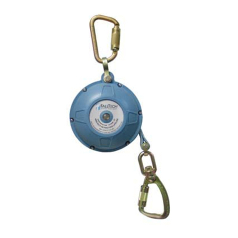
3.1 Purpose: The FT-X Web SRL-P is designed to be used as a component in a Personal Fall Arrest System (PFAS), to provide a
combinaon of worker mobility and fall protecon as required for inspecon work, general construcon, maintenance work, oil produc
on, conned space work, etc.
3.2 Personal Fall Arrest System: A PFAS is an assembly of components and subsystems used to arrest a person during a fall event. A PFAS
typically consists of an anchorage, a deceleraon device such as a Energy Absorbing Lanyard (EAL), a Self-Retracng Device (SRD), or a
Fall Arrestor Connecng Subsystem (FACSS), and a properly ed Full Body Harness (FBH). The SRD discussed in this manual may be used
in non-overhead anchorage situaons. Maximum permissible free fall in a typical PFAS is 6’ (1.8 m). Other applicaons may be below the
D-ring, but no edge exposures are allowed with this product.
3.3 Horizontal Lifeline (HLL) and Rail Systems: The SRL may be aached to rigid and exible anchors provided that all HLL or rail system
applicaons, installaon, and uses are under the supervision of a qualied person.
3.4 Rescue: Ensure a wrien rescue plan, method, and system is in place and readily available for rapid response. Rescues may require
specialized equipment or measures. Rescue operaons are beyond the scope of this manual. See ANSI Z359.4.
3.5 Applicaon Limits: Take acon to avoid moving machinery, abrasive surfaces, and thermal, electrical, including the arc from welding
applicaons, and chemical hazards as contact may damage the SRL, which may result in serious injury or death. The SRL is not
designed for use in restraint, personnel riding, suspension, or work posioning. Rescue applicaons are beyond the scope
of this manual. Do not use the SRL for these applicaons except as a back-up PFAS.
