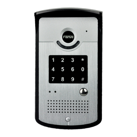
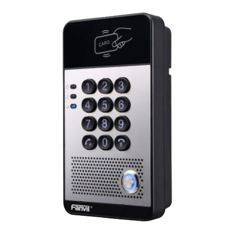
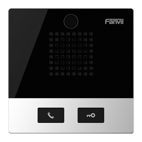
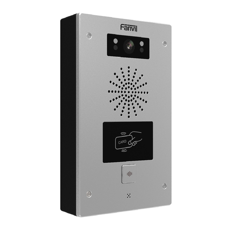
Fanvil PA2 User manual

Software Version: 2.6.0
Release Date:2019/09/20
User Manual
PA2

1
Directory
Directory..........................................................................................................................................1
1 Picture..........................................................................................................................................3
2 Table..............................................................................................................................................5
3 Safety Instruction.........................................................................................................................1
4 Overview.......................................................................................................................................2
5 Install Guide..................................................................................................错误!未定义书签。
5.1 Use POE or external Power Adapter ................................................................................3
5.2 Install................................................................................................................................4
5.2.1 button instruction .....................................................................................................4
5.2.2 Confirm the connection............................................................................................5
5.3 Appendix Table.................................................................................................................6
5.3.1 Common command mode....................................................................................6
5.3.2 Function key LED state ........................................................................................6
6 Basic Introduction........................................................................................................................8
6.1 Quick Setting....................................................................................................................8
6.2 WEB configuration...........................................................................................................8
6.3 SIP Configurations............................................................................................................9
7 Basic Function............................................................................................................................10
7.1 Making Calls...................................................................................................................10
7.2 Answering Calls..............................................................................................................10
7.3 End of the Call................................................................................................................11
7.4 Auto-Answering..............................................................................................................11
7.5 DND................................................................................................................................12
7.6 Call Waiting....................................................................................................................13
8 Advance Function ......................................................................................................................14
8.1 Intercom..........................................................................................................................14
8.2 MCAST...........................................................................................................................14
8.3 Hotspot............................................................................................................................16
9 Web Configurations...................................................................................................................18
9.1 Web Page Authentication ...............................................................................................18
9.2 System >> Information...................................................................................................18
9.3 System >> Account.........................................................................................................19
9.4 System >> Configurations..............................................................................................19
9.5 System >> Upgrade ........................................................................................................20

9.6 System >> Auto Provision ..........................................................................................20
9.7 System >> FDMS...........................................................................................................23
9.8 System >> Tools.............................................................................................................23
9.9 Network >> Basic...........................................................................................................24
9.10 Network >> Advanced..................................................................................................26
9.11 Network >> VPN..........................................................................................................27
9.12 Network >> Web Filter.................................................................................................28
9.13 Line >> SIP...................................................................................................................29
9.14 Line >> Basic Settings..................................................................................................32
9.15 Line >> SIP Hotspot.....................................................................................................33
9.16 Intercom settings >> Blacklist......................................................................................34
9.17 Intercom settings >> Features.......................................................................................34
9.18 Intercom Setting >> Audio...........................................................................................36
9.19 Intercom Setting >> Video ...........................................................................................38
9.20 Intercom Setting >> MCAST .......................................................................................39
9.21 Intercom Setting >> action URL ...............................................................................41
9.22 Intercom Setting >> Time/Date....................................................................................41
9.23 Intercom Setting >> Trusted Certificates......................................................................43
9.24 Intercom Setting >> Device Certificates....................................................................43
9.25 Security Settings...........................................................................................................44
9.26 Function Key >> Function Key Settings ......................................................................46
10 Trouble Shooting......................................................................................................................50
10.1 Get device system information .....................................................................................50
10.2 Reboot device ...............................................................................................................50
10.3 Device factory reset......................................................................................................50
10.4 Network Packets Capture..............................................................................................50
10.5 Common Trouble Cases................................................................................................50

1 Picture
Picture 1 - button instruction..........................................................................................4
Picture 2 - connected graphs..........................................................................................6
Picture 3 - Quickly setting..............................................................................................8
Picture 4 - WEB Login...................................................................................................9
Picture 5 - SIP Line Configuration ...............................................................................9
Picture 6 - Function Setting..........................................................................................10
Picture 7 - - Function Setting.......................................................................................11
Picture 8 - Enable Auto Answer................................................................................11
Picture 9 - Set DND Option ......................................................................................12
Picture 10 - Enable DND .............................................................................................12
Picture 11 - Call Waiting...........................................................................................13
Picture 12 - WEB Intercom.......................................................................................14
Figure 1 - Picture 13 - MCAST....................................................................................15
Picture 14 - SIP Hotspot .............................................................................................17
Picture 15 - WEBAccount.........................................................................................19
Picture 16 - System Setting..........................................................................................19
Picture 17 - Upgrade....................................................................................................20
Picture 18 -Auto provision........................................................................................20
Picture 19 - FDMS.......................................................................................................23
Picture 20 - Tools .........................................................................................................24
Picture 21 - Network Basic Setting..............................................................................24
Picture 22 - Network Setting........................................................................................26
Picture 23 - VPN........................................................................................................27
Picture 24 - WEB Filter Table...................................................................................28
Picture 25 - SIP..........................................................................................................29
Picture 26 - Network Basic..........................................................................................32
Picture 27 - Line Basic Setting..................................................................................33
Picture 28 - SIP Hotspot...............................................................................................34
Picture 29 - Blacklist....................................................................................................34
Picture 30 - Feature......................................................................................................35
Picture 31 -Audio........................................................................................................36
Picture 32 - Video Setting ............................................................................................38
Picture 33 - MCAST....................................................................................................40
Picture 34 -Action URL ..............................................................................................41
Picture 35 - Time/Date..............................................................................................42
Picture 36 - Trusted Certificates...................................................................................43
Picture 37 - Trusted Certificates...................................................................................43
Picture 38 -Alert/Security Settings..............................................................................44
Picture 39 - Function Key Settings ...........................................................................46
Picture 40 - Hot Key Settings.......................................................................................47
Picture 41 - Multicast Settings.....................................................................................47
Picture 42 - Advanced Settings.................................................................................48

2 Table
Table 1 - button instruction ............................................................................................4
Table 2 - Common command mode...............................................................................6
Table 3 - Function key LED state...................................................................................6
Table 4 - Intercom........................................................................................................14
Table 5 - MCAST.........................................................................................................15
Table 6 - SIP Hotspot...................................................................................................16
Table 7 - Auto provision...............................................................................................21
Table 8 - FDMS............................................................................................................23
Table 9 - Network Basic Setting ..................................................................................24
Table 10 - Network Setting ..........................................................................................26
Table 11 - SIP...............................................................................................................29
Table 12 - Line Basic Setting....................................................................................33
Table 13 - Common device function Settings on the web page .............................35
Table 14 - Video Setting...............................................................................................38
Table 15 - MCAST parameters .................................................................................40
Table 16 - Action URL.................................................................................................41
Table 17 - Time/Date.................................................................................................42
Table 18 - Alert/Security Settings ................................................................................44
Table 19 - Function Key Settings..............................................................................46
Table 20 - Hot Key Settings.........................................................................................47
Table 21 - Multicast Settings........................................................................................47
Table 22 - Advanced Settings....................................................................................48

1
3 Safety Instruction
Please read the following safety notices before installing or using this unit. They are
crucial for the safe and reliable operation of the device.
⚫Please use the external power supply that is included in the package. Other power
supply may cause damage to the phone and affect the behavior or induce noise.
⚫Before using the external power supply in the package, please check the home
power voltage. Inaccurate power voltage may cause fire and damage.
⚫Please do not damage the power cord. If power cord or plug is impaired, do not use
it because it may cause fire or electric shock.
⚫Do not drop, knock or shake the phone. Rough handling can break internal circuit
boards.
⚫This phone is design for indoor use. Do not install the device in places where there
is direct sunlight. Also do not put the device on carpets or cushions. It may cause
fire or breakdown.
⚫Avoid exposure the phone to high temperature or below 0℃or high humidity.
⚫Avoid wetting the unit with any liquid.
⚫Do not attempt to open it. Non-expert handling of the device could damage it.
Consult your authorized dealer for help, or else it may cause fire, electric shock and
breakdown.
⚫Do not use harsh chemicals, cleaning solvents, or strong detergents to clean it.
Wipe it with a soft cloth that has been slightly dampened in a mild soap and water
solution.
⚫When lightning, do not touch power plug, it may cause an electric shock.
⚫Do not install this phone in an ill-ventilated place. You are in a situation that could
cause bodily injury. Before you work on any equipment, be aware of the hazards
involved with electrical circuitry and be familiar with standard practices for
preventing accidents.

2
4 Overview
PA2 is a SIP audio and video intercom developed specifically for the needs of industry users.
Media streaming adopts the standard IP/RTP/RTSP protocol. It inherits the advantages of good
stability of azimuthphone and carrier-grade sound quality, and is perfectly compatible with all current
mainstream sip-based IPPBX/ soft switch /IMS platforms, such as Asterisk, Broadsoft, Metaswitch,
3CX, Elastix, etc. It sets a variety of functional interfaces in one: intercom, broadcast, video, security,
recording, broadcast, adapt to a variety of use environment, convenient and rapid deployment of
equipment, is the ideal choice.

3
5 Installation Guide
5.1 Use POE or external Power Adapter
PA2, called as ‘the device’ hereafter, supports two power supply modes, power supply from external
power adapter or over Ethernet (POE) complied switch.
POE power supply saves the space and cost of providing the device additional power outlet. With a
POE switch, the device can be powered through a single Ethernet cable which is also used for data
transmission. By attaching UPS system to POE switch, the device can keep working at power outage
just like traditional PSTN telephone which is powered by the telephone line.
For users who do not have POE equipment, the traditional power adaptor should be used. If the device
is connected to both PoE switch and external power adapter, PA2 will get power supply from PoE
switch in priority, and change to external power adapter once the PoE power supply fails.
Please use the power adapter supplied by Fanvil and the POE switch met the specifications to ensure
the device work properly.

4
5.2 Install
Before you start using the device, please install the following:
5.2.1 button instruction
Picture 1 - button instruction
The image above shows the key layout of the device. Each button provides its own specific function.
The user can refer to the instructions for the keys in the illustration in this section to operate the device.
Table 1 - button instruction
Label
Explanation
①Speaker interface
according to the device input voltage adaptive output maximum power; 4Ω
speaker, POE / 10W, 12V / 10W, 18V / 20W, 24V / 30W. The greater the horn
impedance, the smaller the output power. Suggested wire diameter: 18AWG or larger
diameter.
②Headset interface
Speaker audio line signal output impedance 32 Ohm, single ended output voltage 1.2V,
used for external headphones or active speakers
③LED interface
Output 5V voltage 5 mA current, can be an external LED, indicating the network status,
call status, registration status.
④Function key interface
connection switch, you can log on page set the call number or IP address.
⑤Microphone interface
Recommend the use of 2.2K Ohm impedance electret condenser microphone,
sensitivity: -38dB, bias voltage 2.2V. Microphone signal cable it is recommended to use
a shielded cable and do not connect the shield cable to the grounding screw, improve

5
anti-interference.
⑥Switch input interface
Connect an infrared probe or emergency switch or Doorsensor and other switch
components.
⑦Switch output
interface
corresponding to the short-circuit input interface, login device security page settings,
you can control the alarm light, electric locks and other equipment; with the adjacent
⑧power port connection for external equipment power supply.
⑧Power input interface
12V ~ 24V 2A input, according to the input voltage to determine the maximum output
power amplifier.
⑨Camera interface
standard RJ45 interface, connect the original camera, the proposed use of five or five
sub-network cable
⑩Ethernet interface
WAN port, standard RJ45 interface, 10 / 100M adaptive, support POE input, it is
recommended to use five or super five network cable.
⑪Registration/Network
LED
indicates network status, call status, registration status. Fast flashing: network anomaly
or SIP account exception. Slow flashing: during a call. Always bright: successful
registration.
⑫Volume control key
When device is idle, the button is used to adjust the volume of ringtone, when the
device is in call, the button is used to adjust call volume and when device is having
broadcast, the button is used to adjust broadcast volume.
⑬Restore factory key
press and hold for 3 seconds to flash the device to restart and restore the factory
settings.
⑭Recording output
interface
the local microphone voice and call voice mixed output, suitable for computer and
other equipment recording.
⑮Grounding screw
When PA2’s external part is connected to metal shell or panel, please connect the
external part to this interface, in order to prevent static electricity or other
interferences which may affect the device’s normal working.
5.2.2 Confirm the connection
Confirm whether the equipment of the power cord, network cable and the boot-up is
normal. (Check the network state of light)

6
Picture 2 - connected graphs
5.3 Appendix Table
5.3.1 Common command mode
Table 2 - Common command mode
Action
Description
Standby to IP
Wait for captain to press volume down button 3s to report IP
Switching network
mode
In standby mode, long press the volume button for 10 seconds, and
there will be a beep sound and the indicator light will flash for 5
seconds. Within 5 seconds, press the volume up button for three times
continuously to switch the network mode. Network status is static or
PPPoE mode will be switched to DHCP mode; When the network is
DHCP mode, it will be switched to static IP 192.168.1.128, and IP will be
reported after successful switch
5.3.2 Function key LED state
Table 3 - Function key LED state

7
Type
LED
State
Line/network
Quick flashing
Registration failed/ network abnormal
Normally on
Successfully registered
Slow flashing
In call

8
6 Basic Introduction
6.1 Quick Setting
Before proceeding with this step, make sure your Internet broadband connection is working properly and
complete the network hardware connection. The default factory mode of is fixed IP address mode, which
is 192.168.1.128 by default.
◼Long press the volumedown button on the device for 3 seconds (30 seconds after power on), and
the voice will automatically play the IP address of the device or use the "IP scan tool" software to
find the IP address of the device.(Download
http://download.fanvil.com/tool/iDoorPhoneNetworkScanner.exe)
◼Long press the volume up button for 10 seconds (30 seconds after power on), wait for the speaker
to emit rapid beep sound, then quickly press the volume up button for three times, the beep stops.
After waiting for 10 seconds, the system will automatically broadcast the IP address after
successfully switching to dynamic IP acquisition. Switch again to a fixed IP address.
◼Login to the device's WEB page for configuration according to the IP address
◼Configure the account, user name, server address and other parameters required for registration
provided by the service provider on the WEB configuration page;
Picture 3 - Quickly setting
6.2 WEB configuration
When the device and your computer are successfully connected to the network, enter the IP address of
the device on the browser as http://xxx.xxx.xxx.xxx/ and you can see the login interface of the web page
management.

9
Picture 4 - WEB Login
The username and password should be correct to log in to the web page. The default username and
password are "admin". For the specific details of the operation of the web page, please refer to 9
Web Configurations
6.3 SIP Configurations
At least one SIP line should be configured properly to enable the telephony service. The line
configuration is like a virtualized SIM card. Just like a SIM card on a mobile phone, it stores the service
provider and the account information used for registration and authentication. When the device is
applied with the configuration, it will register the device to the service provider with the server’s
address and user’s authentication as stored in the configurations.
The SIP line configuration should be set via the WEB configuration page by entering the correct
information such as phone number, authentication name/password, SIP server address, server port,
etc. which are provided by the SIP server administrator.
⚫WEB interface:After login into the phone page, enter [Line] >> [SIP] and select SIP1/SIP2 for
configuration, click apply to complete registration after configuration, as shown below:
Picture 5 - SIP Line Configuration

10
7 Basic Function
7.1 Making Calls
After setting the function key to Hot key and setting the number, press the function key to immediately
call out the set number, as shown below:
Picture 6 - Function Setting
See detailed configuration instructions 9.26 Function Key
7.2 Answering Calls
After setting up the automatic answer and setting up the automatic answer time, it will hear the ringing
bell within the set time and automatically answer the call after timeout. Cancel automatic answering.
When a call comes in, you will hear the ringing bell and will not answer the phone over time.

11
7.3 End of the Call
Picture 7 - - Function Setting
You can hang up the call through the Release key (you can set the function key as the Release key) or
turn on the speed dial button to hang up the call. See detailed configuration instructions 9.26 Function
Key.
7.4 Auto-Answering
The user can turn off the auto-answer function (enabled by default) on the device webpage, and the
ring tone will be heard after the shutdown, and the auto-answer will not time out.
Web interface:
enter [Intercom Settings] >> [Features], Enable auto answer, set mode and auto answer time and
click submit.
Picture 8 - Enable Auto Answer
⚫Auto Answer mode:
◼Disable:Turn off the automatic answer function, the device has a call, ring, will not time out to
answer automatically.
◼Line1:Line 1 has an automatic call timeout.

12
◼Line2:Line 2 has an automatic call timeout.
◼Line1 and Line2:Line 1 and line 2 have an automatic call timeout.
◼Lines and IP Call:Line and IP direct dial call timeout automatically answer.
⚫Auto Answer Timeout(0~60)
The range can be set to 0~60s, and the call will be answered automatically when the timeout is set.
7.5 DND
Users can turn on the do-not-disturb (DND) feature on the device's web page to reject incoming calls
(including call waiting). Do not disturb can be set by the SIP line respectively on/off.
Turn on/off all lines of the device without interruption by the following methods:
⚫Web interface: enter [Intercom Settings] >> [Features], set the DND Mode to phone and Enable
DND.
Picture 9 - Set DND Option
Turn on/off the interruption free method for the specific line of the device, as follows:
⚫Web interface: enter [Line] >> [SIP], choose a Line and enter [Line] >> [Advanced settings],
Enable DND.
Picture 10 - Enable DND

13
7.6 Call Waiting
⚫Enable call waiting: new calls can be accepted during a call.
⚫Disable call waiting: new calls will be automatically rejected and a busy signal will be prompted
⚫Enable call waiting tone: when you receive a new call on the line, the device will beep.
Users can enable/disable call waiting in the device interface and the web interface.
⚫Web interface: enter [Intercom Settings] >> [Features], enable/disable call waiting,
enable/disable call waiting tone.
Picture 11 - Call Waiting

14
8 Advance Function
8.1 Intercom
The equipment can answer intercom calls automatically.
Picture 12 - WEB Intercom
Table 4 - Intercom
Parameters
Description
Enable Intercom
When the intercom system is enabled, the device will accept
the SIP header call-info of the Call request
Command automatic call
Enable Intercom Barge
If the option is enabled, PA2 will answer the intercom call
automatically while it is in a normal call, and it will reject new
intercom call if there is already one intercome call
Enable Intercom Mute
Enable mute during intercom mode
Enable Intercom Ringing
If the incoming call is intercom call, the device plays the
intercom tone.
8.2 MCAST
This feature allows user to make some kind of broadcast call to people who are in multicast group.
User can configure a multicast DSS Key on the phone, which allows user to send a Real Time
Transport Protocol (RTP) stream to the pre-configured multicast address without involving SIP
signaling. You can also configure the phone to receive an RTP stream from pre-configured multicast
listening address without involving SIP signaling. You can specify up to 10 multicast listening
addresses.
Other manuals for PA2
2
This manual suits for next models
1
Table of contents
Other Fanvil Intercom System manuals

Fanvil
Fanvil i51W User manual

Fanvil
Fanvil i31S User manual

Fanvil
Fanvil i30 User manual

Fanvil
Fanvil i56A User manual

Fanvil
Fanvil Y50r-Y User manual

Fanvil
Fanvil i20S User manual

Fanvil
Fanvil i10V Installation and user guide

Fanvil
Fanvil i30 User manual

Fanvil
Fanvil i20S User manual

Fanvil
Fanvil i55A&i55A-Z User manual