FAR KJ 17 Setup guide

KJ 17
- ISTRUZIONI ORIGINALI
RIVETTATRICE MANUALE PER INSERTI FILETTATI M3 / M6.
ISTRUZIONI PER L’USO
- TRANSLATION OF ORIGINAL INSTRUCTIONS
HANd TOOL FOR bLINd RIveT NUTS M3 / M6
OPeRATING INSTRUCTIONS
- TRAdUCTION deS INSTRUCTIONS ORIGINALeS
OUTIL à RIveTeR POUR éCROUS à SeRTIR M3 / M6
MOde d’eMPLOI
- ÜbeRSeTZUNG vON ORIGINALANLeITUNGeN
HANdweRkZeUG FÜR bLINd-eINNIeTMUTTeRN M3 / M6
bedIeNUNGSANLeITUNG
- TRAdUCCION de LAS ISTRUCCIONeS ORIGINALeS
ReMACHAdORA MANUAL PARA ReMACHeS ROSCAdOS M3 / M6
INSTRUCCIONeS de USO
I
GB
F
D
E

2750309 - KJ 17 – rev 02 - ( 10-2010 )
4
3
1
5
2
1
0,5 mm
2
6
h
h

3
750309 - KJ 17 – rev 02 - ( 10-2010 )
HAND TOOL FOR BLIND RIVET NUTS FROM M3 TO M6.
Before using it, make sure that the stay bolt and the head assembled on the tool are suitable for the thread of the insert to be used;
otherwise, it will be necessary to change the stay bolt and the head size.
WARNING: The standard stay bolt and head supplied with the tool is usually M6.
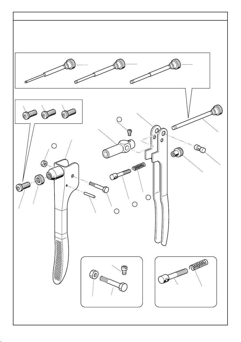
SIZE CHANGE:
Unscrew the head ( 1 ) and the ring nut ( 2).
Loosen the screw ( 3) and take out the stay bolt ( 4); replace it by choising the correct size from the kit.
Each tool is equipped with a stay bolt and a head for each size, the ring nut ( 2) can be fitted with any insert size.
STROKE ADJUSTMENT:
By unscrewing the knob ( 5) the stroke will increase; by screwing the knob ( 5) the stroke will be reduced.
By increasing the stroke, the insert deformation will be greater and therefore, the ( h) distance from the insert head and its
deformation, will be reduced. By reducing the stroke, the ( h) distance will increase because of the smaller deformation.
When the preliminary adjustment has been made, the insert can be fixed on the material to clamp; complete the stroke in accor-
dance with the pressure that the insert needs for the material.
In case of reduced stroke, the insert will not be properly locked, otherwise, in case of wider stroke, the thread will be deformed.
HEAD ADJUSTMENT:
After having set the stroke, it is necessary to adjust the head ( 1). Put the threaded insert on the stay bolt; it is very important
that the head of the insert is fully located. The stay bolt must come out by 0,5 mm from the insert, if this doesn't happen, it is
necessary to unlock the ring nut (2) and adjust the head position: by screwing it, the extention of the stay bolt will increase; by
unscrewing it, the extention of the stay bolt will be reduced. After that you can lock again the ring nut ( 2).
Every time the insert size is changed this adjustment is always necessary.
INSERT OPERATION:
Screw the insert on the stay bolt; position it in the hole of the material and pull the insert by the levers ( 6). After that, unscrew
the stay bolt: now the tool is ready for a new insert.
RIVETTATRICE MANUALE PER L'UTILIZZO DI INSERTI FILETTATI CON FILETTATURA DA M3 A M6.
Prima dell'utilizzo accertarsi che la coppia tirante - testina montata sulla rivettatrice sia adeguata alla filettatura dell'inserto che si vuole
serrare,in caso contrario occorre procedere al cambio di formato.
ATTENZIONE: Solitamente la coppia tirante-testina montata sulla rivettatrice in confezione corrisponde ad una filettatura di M6.
CAMBIO DI FORMATO:
Svitare e togliere la testina ( 1 ) e la ghiera ( 2 )
Allentare la vite ( 3) ed estrarre il tirante ( 4) ;sostituirlo sciegliendo dal kit di corredo la misura necessaria.Ogni rivettatrice è corredata
di un tirante ed una testina per ogni formato di inserto, la ghiera ( 2 ) viene invece utilizzata con tutti i formati.
REGOLAZIONE DELLA CORSA:
Questa operazione deve essere eseguita prima della messa in opera dell'inserto, in funzione dello spessore del materiale da
serrare. La regolazione si ottiene intervenendo sul pomello di registro ( 5 ) svitandolo per aumentare la corsa e avvitandolo per
diminuirla. Aumentando la corsa si ottiene una maggiore deformazione dell'inserto con conseguente diminuzione della distan-
za ( h ) tra la testa dell'inserto e la sua deformazione. Al contrario diminuendo la corsa la distanza ( h ) aumenterà a causa della
minore deformazione. Eseguita la prima regolazione di massima fissare l'inserto sul materiale e rifinire la regolazione della
corsa in base alla stretta che l'inserto opera sul materiale.La corsa ottimale è quella che permette un saldo, ma non esaspera-
to, serraggio dell'inserto sul materiale: in caso di corsa ridotta si rischia il non perfetto bloccaggio ,in caso opposto ,cioè corsa
troppo "ampia" ,si rischia la deformazione del filetto.
REGOLAZIONE DELLA TESTINA:
Una volta definita la corsa regolare la testina ( 1 ) in modo che il tirante faccia presa su tutti i filetti dell'inserto.
Avvitare sul tirante l'inserto filettato in modo che la sua testa vada a battuta con la testina della rivettatrice.
Verificare che il tirante fuoriesca di circa 0,5 mm dall'inserto ,in caso contrario sbloccare la ghiera ( 2 ) e registrare la posizione
della testina: avvitandola aumenterà la sporgenza del tirante,svitandola la sporgenza del tirante diminuirà;
ad operazione ultimata ribloccare la ghiera( 2 ).
Le operazioni di regolazione descritte devono essere sempre ripetute quando avviene il cambio di formato.
SERRAGGIO DELL'INSERTO:
Avvitare l'inserto sul tirante, posizionarlo nel foro praticato sul materiale e serrarlo tramite l'azione della leva ( 6 ).
Ad operazione ultimata svitare il tirante: la rivettarice è pronta per il serraggio di un nuovo inserto.
I
GB

4750309 - KJ 17 – rev 02 - ( 10-2010 )
OUTIL MANUEL POUR L'UTILISATION D'INSERTS DE M3 À M6.
Avant l'emploi vérifier que l'ensemble tirant-tête, monté sur l'outil, soit approprié au filetage de l'insert que l'on veut serrer.
Au cas contraire, il faut pourvoir au changement de diamètre.
ATTENTION: d'habitude l'ensemble tirant-tête assemblé sur l'outil dans le coffret correspond à un filetage de M6.
CHANGEMENT DE DIAMETRE:
Dévisser la tête ( 1) et l'embout ( 2).
Desserrer la vis ( 3) et enlever le tirant ( 4); remplacer le tirant en choisissant la dimension nécessaire dans le kit.
Tous les outils sont livrés avec un tirant et une tête dans chaque diamètre d'insert. L'embout ( 2) est employé pour tous les formats.
REGLAGE DE LA COURSE:
Dévisser la vis de réglage ( 5) pour augmenter la course et visser pour la réduire.
En augmentant la course,l'insert subira une déformation plus importante et la distance ( h) entre la tête de l'insert et sa déformation
subira un écrasement. Au cas contraire, en réduisant la course, la distance ( h) augmentera à cause de la déformation inférieure.
Une fois que l'on a fait le réglage préliminaire, il faut fixer l'insert sur la pièce et ajuster la course en contrôlant le serrage de
l'insert sur l'épaisseur. Au cas où la course est réduite, on risque un blocage incorrect; au cas contraire, c'est-à-dire quand la
course est trop grande, on risque une déformation du filet.
REGLAGE DE LA TETE:
Après le réglage de la course on peut régler la tête ( 1).
Visser l'insert fileté sur le tirant jusqu'au contact de l'insert avec la tête de l'outil.
Vérifier que le tirant sorte de l'insert de 0,5 mm; au cas contraire, débloquer l'embout ( 2) et régler la position de la tête: en la vissant
pour augmenter, ou en dévissant pour diminuer la sortie du tirant. Après avoir effectué cette opération, bloquer l'embout ( 2).
Les opérations citées ci-dessus doivent toujours être répétées quand on change de diamètre ou de longueur d'insert.
SERRAGE DE L'INSERT:
Après avoir vissé l'insert sur le tirant, on doit le positionner dans le trou percé sur le matériel et serrer le levier ( 6).
A la fin de l'opération, dévisser le tirant. L'outil est prêt pour serrer un nouvel insert.
REMACHADORA MANUAL PARA LA UTILIZACION DE REMACHES ROSCADOS CON FILETEADURA DE M3 A M6.
Antes de utilizarla asegurarse que la pareja tirante - cabeza montada sobre la remachadora sea adecuada a la fileteadura del remache
que se desea ajustar, en caso contrario se debe proceder al cambio de formato.
ATENCION: Normalmente la pareja tirante - cabeza montada sobre la remachadora de fábrica corresponde a una fileteadura de M6.
CAMBIO DE FORMATO:
Destornillar y quitar la cabeza ( 1) y la virola ( 2).
Aflojareltornillo(3)yextraereltirante(4);sostituirloeligiendodelkitdefábricalamedidanecesaria.Cadaremachadoraesabastecida
de un tirante y una cabeza para cada formato de remache, la virola ( 2) es utilizada para todos los formatos.
REGULACION DE LA CARRERA:
Esta operación debe ser realizada antes de la puesta en obra del remache, en función del espesor del material a ajustar. La regulación
se obtiene interviniendo sobre el pomo de registro ( 5) desenroscandolo para aumentar la carrera y enroscandolo para disminuirla.
Aumentando la carrera se obtiene una mayor deformación del remache con consiguiente disminución de la distancia ( h) entre la
cabeza del remache y su deformación. Al contrario disminuyendo la carrera la distancia ( h) aumentará a causa de la menor defor-
mación. Realizada la primera regulación de máxima fijar el remache sobre el material y terminar la regulación de la carrera en base al
apretamiento que el remache ejerce sobre el material. La carrera optima es aquella que permite un firme, pero no exasperado, ajuste
del remache sobre el material: en caso de carrera reducida se corre el riesgo de un imperfecto ajuste, en caso opuesto, o sea carrera
muy " amplia ", se corre el riesgo de una deformación en el filete.
REGULACION DE LA CABEZA:
Una vez definida la carrera regular la cabeza ( 1) en modo que el tirante haga toma sobre todos los filetes del remache
Atornillar sobre el tirante el remache roscado en modo que su cabeza vaya a golpe con la cabeza de la remachadora.
Verificar que el tirante sobresalga aproximadamente 0,5 mm del remache, en caso contrario desbloquear la virola ( 2) y registrar la
posición de la cabeza: atornillandola aumentará la parte que sobresale del tirante, desenroscandola la parte sobresaliente del tirante
disminuirá; con la operación terminada bloquear nuevamente la virola ( 2).
Las operaciones de regulación descriptas deben ser siempre repetidas cuando se realiza el cambio de formato.
AJUSTE DEL REMACHE:
Atornillar el remache sobre el tirante, posicionarlo en la perforación practicada sobre el material y ajustarlo a través de la palanca ( 6).
Con la operación terminada desenroscar el tirante: la remachadora está lista para el ajuste de un nuevo remache.
F
E

5
750309 - KJ 17 – rev 02 - ( 10-2010 )
HANDNIET GERATE FÜR BENUTZUNG VON BLINDEINNIETMUTTERN VON M3 BIS M6.
Vor Gebrauch, nachsehen ob die zwei Teile Zugbolze-Kopf, die auf dem Werkzeug montiert sind, zur Blindnietmutter-Gewinde, die
man klemmen will, passen. Wenn es nicht den Fall ist, muss man den richtigen Durchmesser auswählen.
ACHTUNG: Normalerweise ist das Paar " Zugbolze-Kopf " auf dem Werkzeug in M6 montiert.
DURCHMESSERWECHSEL:
Kopf ( 1) und Ansatz ( 2) abschrauben.
Die Schraube ( 3) lockern und den Zugbolzen ( 4) wegnehmen; der Zugbolzen wird gewechselt in dem man die richtige Dimension
aus dem Kit heraus nimmt.
Alle Werkzeuge sind mit Zugbolzen und Köpfe von jedem Durchmesser geliefert. Den Ansatz ( 2) ist für alle Grössen verwendbar.
KURSUSREGULIERUNG:
Regulierschraube ( 5) lockern für den Kursus steigern und schrauben um ihn verkleinern.
Wenn man den Kursus steigert, erträgt die Blindnietmutter eine grössere Verzerrung und die Distanz ( h) zwischen dem Kopf der
Blindnietmutter und seine Verzerrung erträgt eine Quatschung.
Im Gegenteil, wenn man den Kursus reduziert, wird die Distanz ( h) grösser wegen der unteren Verzerrung.
Wenn die Vorregulierung eingestellt ist, muss man die Blindnietmutter auf das Stück setzen und Kursus anpassen in dem man
den Kursus von der Blindnietmutter mit der Dicke kontrolliert.
Im Falle der Kursus reduziert ist, riskiert man eine schlechte Blockierung; im Gegenteil, d.h. wenn der Kursus zu gross ist, riskiert
man eine Gewinde-verzerrung.
KOPF EINSTELLUNG:
Nach der Kursus-Einstellung kann man den Kopf einstellen.
Die Blindnietmutter auf den Zugbolzen schrauben bis Kontakt mit dem Kopf des Werkzeuges.
Prüfen dass der Zugbolze von 0,5 mm aus der Blindnietmutter rausschaut; wenn es nicht den Fall ist, den Ansatz ( 2) deblockieren.
Dann die Kopfstellung einstellen per Schraubung für steigern, oder abschrauben für verringern um den Zugbolze heraus zu machen.
Nach diesem Vorgang, den Ansatz blockieren ( 2).
Dieser Vorgang muss immer wiederholt werden wenn Grösse oder Länge von Blindnietmutter gewechselt werden.
BLINDNIETMUTTERKLEMMUNG:
NachdemmandieBlindnietmutter auf den Zugbolzengeschraubthat,mussmandieBlindnietmutterindasgebohrenes Loch einlegen
und den Hebel ( 6) pressen. Am Ende diesem Vorgang, den Zugbolzen abschrauben. Das Werkzeug ist für eine neue Blindnietmutter
zur Schraubung parat.
D

6
PARTI DI RICAMBIO • SPARE PARTS • PIECES DETACHEES • ERSATZTEILE • PIEZAS DE REPUESTO
750309 - KJ 17 – rev 02 - ( 10-2010 )
17
14 15 16
6
9
78
KIT B
10B(x1)
11B(x1)
18
10 B
11 B
12 A
5A(x1)
12A(x1)
19A(x1)
KIT A
19 A
5 A
2
3
1
4
20
13

7
KITA 741514 Kit Vite M 7 Screw M 7 kit Kit vis M 7
05A 711514 1 Vite TE M7 x 33,5 Screw TE M7 x 33,5 Vis TE M7 x 33,5
12A 710137 1 Vite TCCI M5 x 5,3 Screw TCCI M5 x 5,3 Vis TCCI M5 x 5,3
19A 710048 1 Dado M 7 UNI 5589 Nut M 7 UNI 5589 Ecrou M 7 UNI 5589
KITB 740136 Kit Perno Pin kit Kit pivot
10B 710135 1 Molla Spring Ressort
11B 710136 1 Perno filettato Threaded pin Pivot filete
KIT Indica che il particolare viene venduto in Kit
composti da particolari diversi in quantità
diverse.
It indicates that the part is sold in kits consisting of
different parts in different quantities.
Indique que la pièce est vendue dans des KITS
composés de diverses pièces dans des quantités
différentes.
N° COD. Qt. DESCRIZIONE DESCRIPTION DESCRIPTION KIT
01 721509 1 Leva principale Principal lever Levier principal
02 711510 1 Leva secondaria Secondary lever Levier secondaire
03 711512 1 Corpo Body Corps
04 712287 1 Perno Roll pin Pivot
05A 711514 1 Vite TE M7 x 33,5 Screw TE M7 x 33,5 Vis TE M7 x 33,5 A
06 721516 1 Struttura tirante M 3 Tie rod assembly M 3 Structure tirant M 3
07 721517 1 Struttura tirante M 4 Tie rod assembly M 4 Structure tirant M 4
08 721518 1 Struttura tirante M 5 Tie rod assembly M 5 Structure tirant M 5
09 721519 1 Struttura tirante M 6 Tie rod assembly M 6 Structure tirant M 6
10B 710135 1 Molla Spring Ressort B
11B 710136 1 Perno filettato Threaded pin Pivot filete B
12A 710137 1 Vite TCCI M5 x 5,3 Screw TCCI M5 x 5,3 Vis TCCI M5 x 5,3 A
13 710144 1 Ghiera Ring nut Bague
14 710145 1 Testa M 3 Head M 3 Tête M 3
15 710146 1 Testa M 4 Head M 4 Tête M 4
16 710147 1 Testa M 5 Head M 5 Tête M 5
17 710148 1 Testa M 6 Head M 6 Tête M 6
18 710149 1 Pomello Knob Bouton
19A 710048 1 Dado M 7 UNI 5589 Nut M 7 UNI 5589 Ecrou M 7 UNI 5589 A
20 711521 1 Spina elastica ø 4 x 28 UNI 6873 Spring pin ø 4 x 28 UNI 6873 Goupille élastique ø 4 x 28 UNI 6873
KIT
750309 - KJ 17 – rev 02 - ( 10-2010 )

8
750309 - KJ 17 – rev 02 - ( 10-2010 )
17
14 15 16
6
9
78
KIT B
10B(x1)
11B(x1)
18
10 B
11 B
12 A
5A(x1)
12A(x1)
19A(x1)
KIT A
19 A
5 A
2
3
1
4
20
13
PARTI DI RICAMBIO • SPARE PARTS • PIECES DETACHEES • ERSATZTEILE • PIEZAS DE REPUESTO

9
KITA 741514 Kit Schraube M 7 Kit tornillo M 7
05A 711514 1 Schraube TE M7 x 33,5 Tornillo TE M7 x 33,5
12A 710137 1 Schraube TCCI M5 x 5,3 Tornillo TCCI M5 x 5,3
19A 710048 1 Mutter M 7 UNI 5589 Tuerca M 7 UNI 5589
KITB 740136 Kit Stift Kit perno
10B 710135 1 Feder Muelle
11B 710136 1 Gewindestift Perno fileteado
KIT Dieses Wort gibt an, daß der Teil in KIT von verschiedenen Teilen in
unterschiedlichen Mengen verkauft wird.
Indica que la pieza se vende en juegos formados por piezas distintas en
cantidades distintas.
N° COD. Qt. BESCHREIBUNG DESCRIPCIÓN KIT
01 721509 1 Haupthebel Palanca principal
02 711510 1 Zweithebel Palanca secundaria
03 711512 1 Körper Cuerpo
04 712287 1 Stift Perno
05A 711514 1 Schraube TE M7 x 33,5 Tornillo TE M7 x 33,5 A
06 721516 1 Gewindedorn (Zusammenbau) M 3 Ensamblaje tirante M 3
07 721517 1 Gewindedorn (Zusammenbau) M 4 Ensamblaje tirante M 4
08 721518 1 Gewindedorn (Zusammenbau) M 5 Ensamblaje tirante M 5
09 721519 1 Gewindedorn (Zusammenbau) M 6 Ensamblaje tirante M 6
10B 710135 1 Feder Muelle B
11B 710136 1 Gewindestift Perno fileteado B
12A 710137 1 Schraube TCCI M5 x 5,3 Tornillo TCCI M5 x 5,3 A
13 710144 1 Nutmutter Virola
14 710145 1 Kopfteil M 3 Cabeza M 3
15 710146 1 Kopfteil M 4 Cabeza M 4
16 710147 1 Kopfteil M 5 Cabeza M 5
17 710148 1 Kopfteil M 6 Cabeza M 6
18 710149 1 Knopf Perilla
19A 710048 1 Mutter M 7 UNI 5589 Tuerca M 7 UNI 5589 A
20 711521 1 Spannstift ø 4 x 28 UNI 6873 Clavija elastica ø 4 x 28 UNI 6873
KIT
750309 - KJ 17 – rev 02 - ( 10-2010 )


SISTEMI DI FISSAGGIO
FASTENING SYSTEMS • SYSTEMES DE FIXATION
VERBINDUNGSSYSTEME • SISTEMAS DE FIJACION
SYSTEMY MOCOWANIA • СИСТЕМЫ КРЕПЛЕНИЯ
www.far.bo.it
L’elenco dei centri di assistenza è disponibile sul Ns. sito
web: http://www.far.bo.it ( Organizzazione )
The list of the service centres is available on our website
http://www.far.bo.it ( Organization )
La liste des centres d’assistance est disponible sur notre
site internet http://www.far.bo.it ( Organisation )
Die Liste der Reparaturservices ist verfügbar unter unserer
Webseite http://www.far.bo.it ( Organisation )
La lista de los servicios postventa es disponible en nuestro
sitio web http://www.far.bo.it ( Organización )
Listapunktówserwisowychjestdostępnananaszejstronieinternetowej
http://www.far.bo.it ( Organizacja )
Список сервисных центров приведен на нашем веб-сайте
http://www.far.bo.it ( ОРГАНИЗАЦИЯ )
I
F
E
PL
RUS
GB
D
SEDE • HEAD OFFICE • SIEGE
HAUPTSITZ • SEDE
SIEDZIBA • ОФИСНЫЙ ЦЕНТР :
S.r.l. Uninominale
40057 Quarto Inferiore - Bologna - Italy
Via Giovanni XXIII, 2
Tel. +39 - 051 6009511
Ufficio Vendite Fax +39 - 051 767443
E-mail: commerciale@far.bo.it
Export Dpt. Fax +39 - 051 768284
E-mail: export@far.bo.it
DEPOSITO • WAREHOUSE • DEPOT
WARENLAGER • ALMACEN
ODDZIAŁ • СКЛАД :
20099 Sesto San Giovanni
Milano
Italy
Via Archimede, 8
Tel. +39 - 02 2409634
Fax +39 - 02 26222279
E-mail: milano@far.bo.it
Table of contents
Other FAR Tools manuals
Popular Tools manuals by other brands

TRI tool
TRI tool SEVERMASTER 576AC Operation manual

HOLZMANN MASCHINEN
HOLZMANN MASCHINEN LSR15AIR user manual

Silony Medical
Silony Medical VERTICALE Navigation manual

CMT ORANGE TOOLS
CMT ORANGE TOOLS CMT792 instruction manual

Samoa-Hallbauer
Samoa-Hallbauer PEP 500 VARIO-PAT Technical service guide

Niigata seiki
Niigata seiki DCV Series instruction manual