FAR KJ 70 Setup guide

KJ 70
I
GB
F
E
D
PL
KJ 70
- ISTRUZIONI ORIGINALI
RIVETTATRICE OLEOPNEUMATICA
PER INSERTI M3/M12
ISTRUZIONI D’USO - PARTI DI RICAMBIO
- TRANSLATION OF ORIGINAL INSTRUCTIONS
HYDROPNEUMATIC RIVETING TOOL
FOR INSERTS M3/M12
INSTRUCTIONS FOR USE - SPARE PARTS
- TRADUCTION DES INSTRUCTIONS ORIGINALES
OUTIL À RIVETER OLÉOPNEUMATIQUE POUR
ÉCROUS À SERTIR M3/M12
MODE D’EMPLOI - PIECES DETACHEES
- ÜBERSETZUNG VON ORIGINALANLEITUNGEN
PNEUMATISCH-HYDRAULISCHES NIETWERKZEUG
FÜR BLINDNIETMUTTERN M3/M12
BEDIENUNGSANLEITUNG - ERSATZTEILE
- TRADUCCION DE LAS ISTRUCCIONES ORIGINALES
REMACHADORA OLEONEUMATICA
PARA INSERTOS M3/M12
INSTRUCCIONES DE USO - PIEZAS DE REPUESTO
- TŁUMACZENIE ORYGINALNEJ INSTRUKCJI
NITOWNICA PNEUMATYCZNO-HYDRAULICZNA
DO NITONAKRĘTEK M3-M12
INSTRUKCJA OBSŁUGI - CZĘŚCI ZAMIENNE

KJ 70
Far S.r.l. - Massimo Generali
(Presidente del Consiglio di Amministrazione)
(Chairman of the Board of Directors)
(Président du Conseil d’Administration)
(Vorsitzender des Verwaltungsrates)
(Presidente del Consejo de Administración)
(Prezes Zarzadu)
.............................................
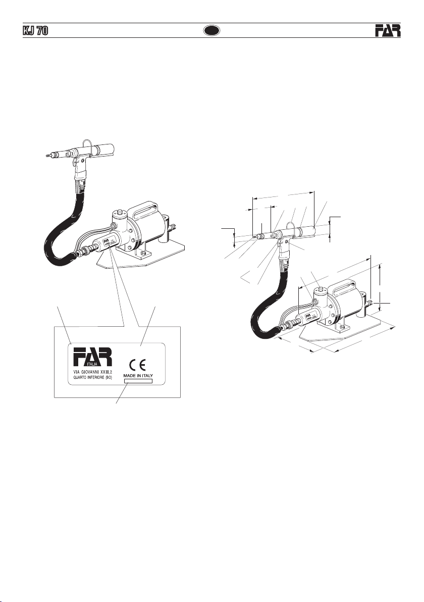
La sottoscritta Far S.r.l., con sede in Quarto Inferiore (BO)
alla via Giovanni XXIII n° 2,
DICHIARA
sotto la propria esclusiva responsabilità che la rivettatrice
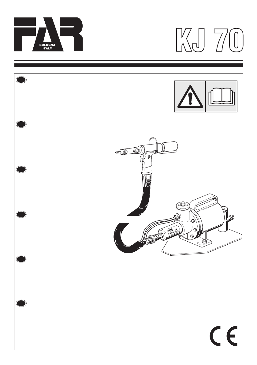
“KJ 70 Rivettatrice oleopneumatica per inserti filettati
M3-M12 con Booster di potenza separato dal corpo
rivettatrice”numerodiserie:vediretro copertina,allaquale
questa dichiarazione si riferisce è conforme ai requisiti
essenziali di sicurezza previsti dal dal D. Lgs. 17/2010
di recepimento della Direttiva Macchine 2006/42/CE e
successive modificazioni ed integrazioni.
La persona autorizzata a costituire il fascicolo tecnico
risponde al nome di Massimo Generali, presso la Far S.r.l.,
consedeinQuartoInferiore(BO)allaviaGiovanniXXIIIn°2
The undersigned Far S.r.l., having its office in Quarto
Inferiore (BO), Via Giovanni XXIII No. 2, herewith
DECLARES
on its sole responsability that the riveting machine
“KJ 70 Hydropneumatic tool for blind rivet nuts M3-M12
Tool body separated from the intensifier” serial number:
see back cover, which is the object of this declaration
complies with the basic safety requirements estabilished
in the law decree Leg. D. 17/2010 of Machinery Directive
2006/42/CE acknowledge and subsequent amendments
and integrations.
The person who is authorized to create the technical
brochure is Massimo Generali, c/o Far S.r.l., head office
in Quarto Inferiore (BO), via Giovanni XXIII n. 2.
LasociétéFarS.r.l.soussignéeavecsiègeàQuartoInferiore
(BO), Via Giovanni XXIII n° 2,
DECLARE
sous sa seule responsabilité que la riveteuse
“KJ70Machineàsertiroléopneumatiquepourinsertsfiletés
M3-M12 Corps du pistolet séparé du booster” numéro de
série: voir la dos couverture, à laquelle cette déclaration
se rapporte est conforme aux conditions essentielles de
sécurité requises par la
loi17/2010d'acceptationdelaDirectiveMachines2006/42/
CE et modifications et intégrations successives.
Lapersonne autorisée àconstituer le dossiertechnique est
Massimo Generali chez FAR S.r.l., avec siège
à Quarto Inferiore (BO) – Via Giovanni XXIII. n.2..
DieUnterzeichnete,Fa. FarS.r.l.,mitSitzinQuarto Inferiore
(BO), Via Giovanni XXIII Nr. 2,
ERKLÄRT
hiermit auf ihre alleinige Verantwortung, daß die
Nietmaschine
“KJ 70 Hydraulisch-pneumatisches Nietwerkzeug
für Blindnietmuttern M3-M12 Werkzeugkörper vom
Verstärker getrennt” seriennummer: siehe Rückseite ,
auf das sich diese Erklärung bezieht, den wesentlichen
Sicherheitsanforderungen des Gesetzesdekrets 17/2010
von Umsetzung der Maschinenrichtlinie 2006/42/CE
und den nachfolgenden Änderungen und Anfügungen
entspricht.Der Berechtigte zur Bildung der technische
Broschüre ist Massimo Generali, bei der Firma Far S.r.l.,
mit Sitz in Quarto Inferiore (BO), via Giovanni XXIII Nr. 2..
LafirmatariaFar S.r.l.,domiciliadaen QuartoInferiore (BO)
en via Giovanni XXIII n° 2,
DECLARA
bajo su exclusiva responsabilidad que la remachadora
“KJ 70 Remachadora oleoneumática para remaches
roscadosM3-M12Boosterdepotenciaseparadodalcuerpo
de la remachadora” número de serie: ver la contratapa,
a la cual la presente declaración se refiere corresponde
a los requisitos esenciales de seguridad previstos porel
D.Lay 17/2010 de recepción de la Directiva Maquinas
2006/42/CE y sucesivas modificaciones e integraciones.
La persona autirizada a constituir el fasciculo tecnico es
Massimo Generali,
cerca FAR S.r.l., con sede a Quarto Inferiore (BO) – Via
Giovanni XXIII n.2.
NiżejpodpisanarmaFarS.r.l.,zsiedzibąwQuartoInferiore(BO),
via Giovanni XXIII nr 2,
OŚWIADCZA
na własną i wyłączną odpowiedzialność, że nitownica„
KJ 70 Nitownica hydrauliczno-pneumatyczna do nitonakrętek
gwintowanychM3-M12zbusteremmocyoddzielonymodkorpusu
nitownicy”, numer seryjny: patrz tylna okładka, do której odnosi
sięniniejszadeklaracja,jestzgodnazwymogamibezpieczeństwa
przewidzianymiprzezdekretlegislacyjny17/2010implementujący
Dyrektywę Maszynową 2006/42/WE wraz z późniejszymi
zmianami i uzupełnieniami.
Osobą upoważnioną do utworzenia dokumentacji technicznej
jest Massimo Generali z rmy Far S.r.l. mającej siedzibę w Quarto
Inferiore (BO), via Giovanni XXIII nr 2.
Quarto Inferiore, 01-03-2019
I
GB
F
E
PL
D

I
I
F
F
E
PL
PL
ISTRUZIONI D’USO.................................................4
INSTRUCTIONS FOR USE.......................................9
MODE D’EMPLOI..................................................14
BEDIENUNGSANLEITUNG.....................................19
INSTRUCCIONES DE USO.....................................24
INSTRUKCJA OBSŁUGI...............................................29
PARTI DI RICAMBIO .............................................34
SPARE PARTS.......................................................36
PIECES DETACHEES .............................................38
ERSATZTEILE........................................................40
CZĘŚCI ZAMIENNE ....................................................42
KJ 70
GB
GB
D
D

IKJ 70
4Date 07-2016 Revisione - 12
ISTRUZIONI D’USO
INDICE
GARANZIA E ASSISTENZA TECNICA.....................................4
AVVERTENZE E MISURE DI SICUREZZA...............................4
IDENTIFICAZIONE DELLA RIVETTATRICE.............................5
NOTE GENERALI E CAMPO DI APPLICAZIONE.....................5
PARTI PRINCIPALI................................................................5
DATI TECNICI........................................................................5
POSA IN OPERA DELL’INSERTO...........................................6
CAMBIO DI FORMATO ..........................................................7
RABBOCCO OLIO CIRCUITO OLEODINAMICO......................8
SMALTIMENTO DELLA RIVETTATRICE.................................8
ATTENZIONE!!!
La mancata osservanza o trascuratezza delle seguenti
avvertenze di sicurezza può avere conseguenze sulla
vostra o altrui incolumità e sul buon funzionamento
dell’utensile.
•Leggereattentamenteleistruzioniprimadell’uso.
•Perleoperazionidimanutenzionee/oriparazioneaffidarsi
a centri di assistenza autorizzati dalla FAR s.r.l. e fare uso
esclusivo di pezzi di ricambio originali. La FAR s.r.l. declina
ogni responsabilità per danni da particolari difettosi, che
si dovessero verificare per inadempienza di quanto sopra
(Direttiva CEE 85/374).
L’ELENCO DEI CENTRI DI ASSISTENZA È DISPONIBILE SUL
NS. SITO WEB: http://www.far.bo.it ( Organizzazione )
•Siraccomandal’usodell’utensileda partedipersonale
specializzato.
•Durantel’impiego dell’utensile,usare occhialiovisiere
protettive e guanti.
•Perleoperazionidicaricaolio,usaresolofluidicon
caratteristiche indicate nel presente fascicolo.
•Incasodiperditeaccidentalidioliochedovesserovenire
a contatto con la pelle, lavarsi accuratamente con acqua e
sapone alcalino.
•L’utensilepuòesseretrasportatoamanoedèconsigliabile,
dopo l’uso, riporlo nel proprio imballo.
GARANZIA E ASSISTENZA TECNICA
Le rivettatrici FAR sono coperte da garanzia di 12 mesi.
Il periodo di garanzia dell'attrezzo decorre dal momento
della sua comprovata ricezione da parte dell'acquirente. La
garanzia copre l'utente/acquirente quando l'attrezzo viene
acquistatoattraversounrivenditoreautorizzatoesoloquando
viene impiegato per gli usi per i quali è stato concepito. La
garanzia non è valida se l'attrezzo non viene utilizzato e se
non viene sottoposto a manutenzione come specificato nel
manuale di istruzione e manutenzione. In caso di difetti o
guasti la FAR S.r.l. si impegna unicamente a riparare e/o
sostituire, a propria discrezione esclusiva, i componenti
giudicati difettosi.
AVVERTENZE E MISURE Dl SICUREZZA
•Siconsigliaaifinidi uncorretto funzionamentodella
rivettatrice, una revisione semestrale.
• Gliinterventidiriparazioneepuliziadell’utensiledovranno
essere eseguiti con macchina non alimentata dall’aria
compressa.
• Èconsigliabile, ovepossibile, I’usodiun bilanciatoredi
sicurezza.
• Incasodiesposizionequotidianapersonaleinambienteil
cui livello di pressione acustica dell’emissione ponderata
A sia superiore al limite di sicurezza di 70 dB (A), fare uso
di adeguati mezzi individuali di protezione dell’udito (cuffia
o tappo antirumore, diminuzione del tempo di esposizione
quotidiana etc...).
• Mantenereilbancoe/ol’areadilavoropulitaeordinata,il
disordine può causare danni alla persona.
• Nonlasciare chepersoneestranee allavorotocchino gli
utensili.
• Assicurarsicheitubidialimentazionedell’ariacompressa
siano correttamente dimensionati per l’uso previsto.
• Nontrascinarel’utensilecollegatoall’alimentazionetirandolo
per il tubo; mantenere quest’ultimo lontano da fonti di calore
e da oggetti taglienti.
• Manteneregli utensiliinbuono statod’uso epuliti,non
rimuovere mai le protezioni e il silenziatore dell’utensile.
•Dopoavere eseguitooperazionidi riparazione e/o
registrazione assicurarsi di avere rimosso le chiavi di servizio
o di registrazione.
•Primadi scollegareil tubodialimentazione dell’aria
compressa dalla rivettatrice, assicurarsi che quest’ultimo
non sia in pressione.
• Attenersiscrupolosamenteaquesteistruzioni.

5
I
KJ 70
Revisione - 12 Date 07-2016
IDENTIFICAZIONE DELLA RIVETTATRICE
La rivettatrice KJ 70 è identificata da una marcatura indicante
ragione sociale e indirizzo, designazione della macchina ,
marcatura CE. In caso di richiesta di assistenza tecnica fare
sempre riferimento ai dati riportati nella marcatura.
NOTE GENERALI E CAMPO DI APPLICAZIONE
L’uso dell’utensile è finalizzato esclusivamente all’utilizzo di
inserti filettati con filetto compreso tra M3 e M12.
Il sistema oleopneumatico utilizzato dalla rivettatrice KJ 70
fornisce una maggior potenza rispetto al tradizionale sistema
pneumatico su cui si basano altri modelli di rivettatrici. Ciò
significaunadrasticariduzionedeiproblemidovutiall’usuradei
componenti con conseguente aumento di affidabilità e durata.
Le soluzioni tecniche adottate riducono le dimensioni e il peso
della macchina rendendo la rivettatrice KJ 70 assolutamente
maneggevole.Lapossibilitàdiperditedalsistemaoleodinamico
sonopreclusedall’impiegodiguarnizioniatenutacheeliminano
questo problema.
DATI TECNICI
• Pressionediesercizio ................................................6 BAR
• Diametrointernominimotuboalimentazione
aria compressa .......................................................... 8 mm
• Consumomaxarialibera,perciclo......................... 10,4 Nl
• Forzamassima......................................... 6 BAR - 30143 N
PESO:
• Pistola...................................................................2,050 Kg
• Totale....................................................................6,850 Kg
• Temperaturadiutilizzo........................................-5°/+50 C°
• Valoremedioquadraticoponderatoin
frequenza dell’accelerazione complessiva (Ac)
a cui sono sottoposte gli arti superiori................< 2,5 m/s2
• Pressioneacusticadell’emissioneponderata(A)..... 78 dBA
• Pressioneacusticaistantaneaponderata(C) ......< 130 dBC
• Potenzaacusticaponderata(A) ............................... 90 dBA
PARTI PRINCIPALI
A)................................................. Ghiera bloccaggio testina
B).................. Foro inserimento spina sbloccaggio innesto
C)...........................................................Attacco bilanciatore
D).................................................. Ghiera regolazione corsa
E) ...........................................................Motore pneumatico
F) .................................................................. Tirante filettato
G)................................................................................Testina
H)............................ Grilletto di comando: pos.1 Trazione -
............................................................- pos.2 Svitamento
I).......................................... Allacciamento aria compressa
L) ...............................................................Tappo carico olio
M).............................................................. Tappo di servizio
N)......................................................Segnalatore livello olio
KJ 70
KJ 70
Ragione sociale e indirizzo
del fabbricante
Designazione
macchina
Numero di serie
KJ 70
150
315
165
Ø 25
90
350
Ø 44
265
A
I
M
NL
H
2
1
F
E
BCD
G
ALIMENTAZIONE DELL’ARIA
L’aria di alimentazione deve essere libera da corpi estranei e da
umidità per proteggere la macchina da usura precoce
delle parti in movimento; è consigliabile, pertanto, l’impiego di
un gruppo lubrificatore per aria compressa.

IKJ 70
6Date 07-2016 Revisione - 12
ATTENZIONE!!! LA REGOLAZIONE NON CORRETTA DELLA CORSA DELLA RIVETTATRICE
PUÒ CAUSARE IL CATTIVO SERRAGGIO DEGLI INSERTI E LA ROTTURA DEL TIRANTE!
POSA IN OPERA DELL’INSERTO
Verificare che la coppia tirante-testina montata sulla rivettatrice sia adeguata alla misura dell’inserto che si vuole serrare; in caso
contrario procedere al cambio di formato. Solitamente la coppia tirante-testina montata sulla rivettatrice in confezione corrisponde
ad una filettatura di M 10. Prima di utilizzare la rivettatrice e dopo ogni cambio di formato occorre eseguire le seguenti operazioni
in funzione del formato e dello spessore del materiale da serrare.
Inserire nelle tacche della ghiera di regolazione corsa I’apposita chiave (in dotazione). Regolare la corsa della rivettatrice al minimo,
ruotando per quanto possibile la ghiera “G” nel senso indicato dal simbolo “–”. Inserire l’inserto sul tirante ed esercitare su di esso
una leggera pressione; in questo modo l’inserto si avvita automaticamente sul tirante. Assicurarsi che la testa dell’inserto vada
in battuta con la testina della rivettatrice. Fissare l’inserto e verificare il serraggio che questo opera sullo spessore del materiale.
Regolare la corsa della rivettatrice mediante la rotazione della ghiera “G”, in funzione del serraggio desiderato, considerando che
all’aumentare della corsa (rotazione della ghiera “G” nel senso indicato dal simbolo “+”) la distanza “h” tra testa e deformazione
dell’inserto diminuisce con conseguente aumento dell’azione di serraggio.
+
–
H
H
G

7
I
KJ 70
Revisione - 12 Date 07-2016
CAMBIO DI FORMATO
Al variare della filettatura degli inserti da serrare, occorre eseguire la sostituzione della coppia Tirante/testina, pertanto procedere
come segue:
FIG. 1. Allentare la ghiera con una chiave commerciale di mm 22 e rimuovere la testina.
FIG. 2. Fare passare la spina (in dotazione) attraverso l’apposito foro di servizio,situato nel canotto porta testina, ed esercitare
su di essa una pressione verso l’interno in modo da sbloccare l’innesto dal tirante. Contemporaneamente svitare il tirante ed
estrarlo leggermente.
FIG. 3-4. Mantenendo sbloccato l’innesto avvitare il formato di tirante desiderato. Completata la sostituzione del Tirante ruotarlo
leggermente fino a che non si avverte lo scatto d’innesto, procedere quindi al montaggio della relativa testina bloccandola con
l’apposita ghiera allentata in precedenza. Ogni volta che si effettua il cambio di formato ripetere le operazioni di registrazione
riportate nelle pagine precedenti.
ATTENZIONE! LE OPERAZIONI SOPRAELENCATE DEVONO ESSERE ESEGUITE CON MACCHINA NON ALIMENTATA.
22 mm.
22 mm.
1 2
34

I
8Date 07-2016 Revisione - 12
KJ 70
ATTENZIONE! Prima di scollegare il tubo dell’aria compressa dalla rivettatrice accertarsi che quest’ultimo non
sia in pressione! Si raccomanda l’uso di olio HLP 32 cSt o simili.
SMALTIMENTO DELLA RIVETTATRICE
Per lo smaltimento della rivettatrice attenersi alle prescrizioni imposte dalle leggi nazionali.
Dopo aver scollegato la macchina dall’impianto pneumatico, procedere allo smontaggio dei vari componenti
suddividendoli in funzione della loro tipologia: acciaio, alluminio, materiale plastico, ecc.
Procedere quindi alla rottamazione nel rispetto delle leggi vigenti.
RABBOCCO OLIO CIRCUITO OLEODINAMICO
Verificare periodicamente che il livello dell’olio non scenda mai al di sotto dei 3/4 indicati dall’apposito segnalatore (B). Nel caso si rendesse
necessario un rabbocco togliere il tappo (A) servendosi di una chiave di mm 17, quindi immettere olio idraulico HLP 32 CST finché questo non
raggiunge il bordo del foro filettato.
ATTENZIONE ! Nel caso questa operazione non venga effettuata, si potrà riscontrare, nel tempo, un calo di corsa della rivettatrice che andrà
accentuandosi fino a comprometterne il funzionamento. Occorrerà pertanto eliminare la presenza d’aria all’interno del circuito oleodinamico e
ripristinarne la corretta quantità di olio. Procedere quindi come segue: Riporre il corpo rivettatrice all’interno di un raccoglitore (in modo da non
disperdere eventuali fuoriuscite di olio) e posizionare la parte superiore del booster in modo tale che si trovi esattamente sullo stesso piano
del corpo rivettatrice, mentre i tubi di alimentazione devono essere disposti come da figura. Rimuovere il tappo di rabbocco olio (A) e il tappo
di servizio (C) servendosi rispettivamente di una chiave commerciale di mm. 17 e di una chiave commerciale a brugola di mm.5. Immettere olio
idraulico HLP 32 CST fino a che questo non uscirà privo di tracce di aria (bolle) dal foro liberato dal tappo di servizio (C). Ad operazione ultimata
rimontare il tappo di servizio (C) e verificare che l’olio abbia raggiunto il bordo del foro filettato, rimontare quindi il tappo (A) e pulire accuratamente
larivettatricedall’oliofuoriuscito.Èestremamenteimportanteattenersialleistruzionisopraindicateedeffettuareleoperazionidirabboccoolio
muniti di guanti.L’olio fuoriuscito durante le operazioni indicate, dovrà essere raccolto in appositi recipienti ed affidato successivamente ad una
ditta autorizzata per lo smaltimento del rifiuto. Non schiacciare o tagliare i tubi che collegano la rivettatrice al booster.
Ach.17mm
IMPORTANTE: Assicurarsi che il tappo di rabbocco
olio (G) venga serrato con una coppia pari a:
Min. 5 Nm ÷ Max. 8 Nm.
min. 5 Nm
max. 8 Nm
C
B
KJ70
K
J
7
0

9
GB
Revisione - 12 Date 07-2016
KJ 70
INSTRUCTIONS FOR USE I
INDEX
GUARANTEE AND TECHNICAL ASSISTANCE.............................. 9
SAFETY MEASURES AND REQUIREMENTS ............................... 9
TOOL IDENTIFICATION ............................................................. 10
GENERAL NOTES AND USE...................................................... 10
MAIN COMPONENTS ................................................................ 10
TECHNICAL DATA ..................................................................... 10
PLACING OF THE INSERT......................................................... 11
CHANGE OF SIZE ..................................................................... 12
TOOPING UP THE OIL-DYNAMIC CIRCUIT............................... 13
DISPOSAL OF THE RIVETING TOOL ......................................... 13
CAUTION!!!
All the operations must be done in conformity with the
safety requirements, in order to avoid any consequence
for your and other people security and to allow the best
tool work way.
•Readtheinstructionscarefullybeforeusingthetool.
•For allmaintenanceand/or repairspleasecontact FAR
s.r.l. authorized service centers and use only original
spare parts. FAR s.r.l. may not be held liable for
damages from defective parts caused by failure to
observe what mentioned above (EEC directive
85/374).
The list of the service centres is available on our website
http://www.far.bo.it ( Organization )
•Thetoolmustbeusedonlybyexpertworkers.
•Aprotectivevisorandglovesmustbeputonwhenusing
the tool.
•Fortoppingup theoil, wesuggestusing onlyfluidsin
accordance with the features specified in this working book.
•Ifanydropofoiltouchesyourskin,youmustwashwith
water and alkaline soap.
•Thetoolcanbecarriedandwesuggestputtingitintoitsbox
after using.
GUARANTEE AND TECHNICAL ASSISTANCE
FAR riveting tools are covered by a 12-month warranty. The
tool warranty period starts on the date of delivery to the
buyer, as specified in the relevant document. The warranty
covers the user/buyer provided that the tool is purchased
through an authorized dealer and only if it is used for the
purposes for which it was conceived. The warranty shall
not be valid if the tool is not used or maintained as specified
in the instruction and maintenance handbook. In the event
of defects or failures, FAR S.r.l. shall undertake solely to
repair and/or replace the components it judges to be faulty.
SAFETY MEASURES AND REQUIREMENTS
• Thetoolneedsathoroughsix-monthlyoverhaul.
• Repairingandcleaningoperationsmustbedonewhenthe
tool is not fed.
• Asafetybalancerissuggestedwhenitispossible.
• IftheA-weightedemissionsoundpressurelevelismorethan
70 dB (A), you must use some hearing protections (anti-noise
headset, etc.).
• Theworkbenchandtheworksurfacemustbealwaysclean
and tidy. The untidy can cause damages to people.
• Donotallowunauthorizedpersonstousetheworkingtools.
• Makeyousurethatthecompressedairfeedinghoseshave
the correct size to be used.
• Donotcarrytheconnectedtoolbypullingthehose.Thehole
must be far from any heating sources or from cutting parts.
• Keepthetoolsingoodconditions;donotremoveeithersafety
parts or silencers.
• Afterrepairingand/oradjusting,makesureyouhavealready
removed the adjusting spanners.
• Beforedisconnectingthecompressedairhosefromthetool
make sure that there is no pressure in the hose.
• Theseinstructionsmustbecarefullyfollowed.

GB
10 Date 07-2016 Revisione - 12
KJ 70
TOOL IDENTIFICATION
The riveting tool KJ 70 is identified from a marking that shows
company name and address of manufacturer, designation of
the tool, CE. Always refer to the information on the riveting tool
when requesting technical service.
GENERAL NOTES AND USE
The tool can be employed only for blind rivet nuts with thread
of M3 ÷ M12 diameter.
The KJ 70 oil pneumatic system assures more power than
the pneumatic system used for other models. That means
a reduction in the problems due to the wear and tear of the
components, therefore, there will be an increase in reliability.
Thetechnicai solutions adopted reduce the dimensions and the
weight of the tooi which, for these reasons, make it very handy.
The possibilities of leakage from the oil-dynamic system, are
eliminated by some sealed gaskets, which solve this problem.
TECHNICAL DATA
• Workingpressure ......................................................6 BAR
• Min.int.diam.ofthecompressedair
feeding hose ....................................... min. diam = 8 mm
• Airconsumptionpercycle ...................................... 10,4 Nl
• Maxpower.................................................6 BAR -13656 N
WEIGHT:
• Gun.......................................................................2,050 Kg
• Total......................................................................6,850 Kg
• Workingtemperature...........................................-5°/+50°C
• Rootmeansquareintotalaccelerationfrequency(Ac)
to which the arms are subjected.........................< 2.5 m/s2
• A-weightedemissionsoundpressurelevel.............78 dBA
• PeakC-weightedinstantaneoussoundpressure<130 dBC
• A-weightedsoundpower........................................ 90 dBA
MAIN COMPONENTS
A) .....................................................Ring nut clamping head
B) ................................ Insertion Pin Hole Dechucking clutch
C) ...........................................................Balancer connection
D) ................................................Ring nut adjustment stroke
E) ............................................................... Pneumatic motor
F) .................................................................Threaded tie rod
G) ...................................................................................Head
H)........... Drive trigger: Pos. 1 Tiraction - Pos. 2 Unscrewing
I) ................................................... Compressed air connection
L) .......................................................................Oil filler plug
M) ......................................................................Service plug
N)................................................................ Oil level indicator
KJ 70
KJ 70
KJ 70
150
315
165
Ø 25
90
350
Ø 44
265
A
I
M
NL
H
2
1
F
E
BCD
G
AIR FEED
The air feed must be free from foreign bodies and humidity in
order to protect the tool from premature wear and tear
of the components in movement, therefore we suggest to use
a lubrificator group for compressed air.
Company name and
address
Designation of
the tool
Serial number

11
GB
Revisione - 12 Date 07-2016
KJ 70
WARNING!!! A WRONG ADJUSTMENT OF THE RIVETING TOOL STROKE
MAY CAUSE A FAULTY CLAMPING OF INSERTS AND MAY BRAKE THE TIE ROD!
PLACING OF THE INSERT
Make sure that the couple tie-rod/head mounted on your riveting tool is suitable for the insert to clamp; otherwise, change size
accordingly. Usually the riveting tool is supplied with the couple tie-rod/head corresponding to a M 10 thread. Before using the
riveting tool and after any change of size, perform the following operations according to the size and thickness of the part to
clamp. Plug in the notchs of the regulation stroke ring nut the special key (issued). Adjust the riveting tool stroke to the minimum
by turning the ring nut “G” to “–” marked on the tool. Place the insert on the tie rod and push slightly on it so as to make it clamp
automatically. Make sure the insert head touches the riveting tool head properly. Fasten the insert and in order to ensure a proper
clamping of the material, adjust the riveting tool stroke by turning the ring nut “G” accordingly. By increasing stroke, i.e. by turning
the ring nut “G” to “+”, the distance “h” between head and insert deformation will decrease and clamping will result more effective.
+
–
H
H
G

GB
12 Date 07-2016 Revisione - 12
KJ 70
CHANGE OF SIZE
Depending on insert thread, it is necessary to replace the couple “tie-rod/head” as follows:
PICTURE 1. Loosen the ring nut by means of a 22-mm standard spanner and remove the riveting tool head.
PICTURE 2. Make the pin supplied pass through the pertinent service hole located on the cone carrying head and apply a light
pressure on the head inwards, in order to dechuck the tie rod clutch., at the same time, unscrew the tie rod and extract it.
PICTURE 3-4. Keep the clutch dechucked and screw the tie rod size desired. When the replacement of the tie rod has been
performed, swing it until you hear a click. Them assembly the proper head and lock it with the corresponding ring nut loosen
before. Each time you carry out any change of size, repeat the adjustment operations as specified in the previous pages.
WARNING! DESCONNECT AIR FEED WHEN PERFORMING THOSE OPERATIONS.
22 mm.
22 mm.
1 2
34

13
GB
Revisione - 12 Date 07-2016
KJ 70
TOPPING UP THE OIL-DYNAMIC CIRCUIT
Verify periodically that the oil level does not go below 3/4 of the limit indicated by the proper indicator (
B
). Whether you need to top up
the circuit, remove the plug (
A
) by means of a 17-mm wrench, then pour hydraulic oil,
HLP 32 CST
, until it reaches the border of the
threaded hole.
WARNING!
If you fail to perform this operation, you will note power loss that will lead to jeopardise the proper working of the tool.
Therefore, you need to get rid of the air from the tool and restore the exact oil level in the oil-dynamic circuit.
Proceed as follows: put the riveting gun inside a container, in order to avoid loosing oil, and put the upper side of the booster on the same
level of the gun/and lay the feed hoses as the picture shows. Remove the oil screw cap (
A
) and the service plug (
C
) by using a 17-mm
wrench and a 5-mm allen wrench respectively. Pour oil
HLP 32 CST
until it flows from the hole, without plug (
C
), completely free from
air bubbles. When the operation has been carried out, replace the plug (
C
) and make sure that oil has reached the border of the threaded
hole. Screw the screw cap (
A
) and clean carefully the riveting tool from overflowed oil. It is very important to apply carefully to the
instructions and use always gloves when you handle the tool. Overflowed oil, during the topping, must be collected in proper containers
anddeliveredafterwards,tospecializedwasteoilgettheringcompany. Donotsmashorcuttheconnectinghosesbetweengunandbooster.
WARNING! Before disconnecting the compressed air hose, make sure that it is not under pressure!
We recommend to use oil HLP 32 cSt or similars.
DISPOSAL OF THE RIVETING TOOL
Follow the prescriptions of the national laws for disposing of the riveting tool.
After disconnecting the tool from the pneumatic system, disassemble and split all the components according
to the material: steel, aluminium, plastic material, etc.
Then proceed to scrap the materials in accordance with current laws.
Ach.17mm
WARNING: Make sure that the oil filler cap (A)
is tightened at a torque corresponding to Min.
5 Nm ÷ Max. 8 Nm.
min. 5 Nm
max. 8 Nm
C
B
KJ70
K
J
7
0

F
14 Date 07-2016 Revisione - 12
KJ 70
MODE D’EMPLOI
INDEX
GARANTIE ET ASSISTANCE TECHNIQUE.................................. 14
INSTRUCTIONS ET MESURES DE SECURITE........................... 14
IDENTIFICATION DE L’OUTIL DE POSE..................................... 15
CARACTERISTIQUES ET EMPLOI ............................................. 15
PARTIES PRINCIPALES ............................................................ 15
CARACTERISTIQUES TECHNIQUES.......................................... 15
POSE DE L’INSERT.................................................................... 16
CHANGEMENT DE FORMAT...................................................... 17
REMPLISSAGE DE L’HUILE DU CIRCUIT HYDRAULIQUE......... 18
ELIMINATION DE LA RIVETEUSE.............................................. 18
ATTENTION!!!
Le non respect des instructions suivantes peut
avoir des conséquences désagréables pour
vous-mêmes et pour l’intégrité d’autrui.
•Lisez avec soin la notice avant l’usage.
•Pour les opérations d’entretien et/ou réparations, adressez-
vous aux centres de service après-vente autorisés de FAR
s.r.l. et n’utilisez que des pièces détachées originales.
FAR s.r.l. décline toute responsabilité pour les dommages
dus à des pièces défectueuses qui interviendraient suite au
non-respect de la notice ci-dessus (Directive CEE 85/374).
La liste des centres d’assistance est disponible sur notre site
internet http://www.far.bo.it ( Organisation )
•L’outil de pose doit être utilisé par le personnel spécialisé.
•Pendant l’utilisation de l’outil utiliser des gants et des lunettes
de protections ou une visière
•Pour le remplissage de l’huile, il faut utiliser les fluides
indiqués dans ce dossier.
•Encasdefuitesimprévuesdehuile(aucontactdelapeau),
il faut se laver soigneusement avec de l’eau et du savon
alcalin.
•L’outildeposepeutêtretransportéàlamainetildoitêtre
remis dans sa boîte après l’usage.
GARANTIE ET ASSISTANCE TECHNIQUE
Les riveteuses FAR sont sous garantie pendant 12 mois. La
période de garantie de l'outil commence à partir du moment
où il est avéré que son acquéreur en prend possession. La
garantiecouvrel'utilisateur/acquéreurquandl'outilestacheté
chez un revendeur agréé et uniquement quand il est utilisé
aux fins pour lesquelles il a été conçu. La garantie n'est pas
valable si l'outil n'est pas utilisé et s'il n'est pas soumis à
l'entretien tel qu'il est spécifié dans le manuel d'utilisation et
d'entretien. En cas de défauts ou de pannes, la société FAR
S.r.l. s'engage uniquement à réparer et/ou à remplacer, à sa
seule discrétion, les composants jugés défectueux.
INSTRUCTIONS ET MESURES DE SECURITE
• Pourobtenirunbonfonctionnementdel’outil,nousvous
suggérons de le réviser tous les six mois.
• Lesinterventionsderéparationsetdenettoyagesdel’outil
doivent se faire machine non alimenté en air.
• Sipossible,ilfaudraitutiliserdeséquilibreursdesécurité.
• Encasd’expositionquotidienneoùleniveaudepressionsoit
supérieur à la limite de sécurité 70 dB (A), l’on doit assurer
la protection de l’ouïe (casque antibruit, réduction du temps
d’exposition quotidienne, etc).
• Latableetlepostedetravaildoiventêtretoujourspropres
et rangés. Le désordre peut causer des dommages aux
personnes.
• Lespersonnesnonauthoriséesnepeuventpasseservirdes
outils de pose.
•Ilfaut s’assurerquelestuyauxd’alimentationdel’air
comprimé soient appropriés (conformes) à l’utilisation
prévue.
• Nepas transporterl’outilde posequandil estconnecté
à l’alimentation. Le tuyau doit se trouver toujours loin de
sources de chaleur ou d’objets tranchants.
• Lesoutilsdeposedoiventêtretoujoursenbonétat.Nepas
enlever les protections et le silencieux de l’outil.
• Aprèslaréparation et/ouréglage,ilfaut s’assurerd’avoir
enlever les clés de réglage.
• Avantdedébrancherletuyaud’alimentationd’aircomprimé
de l’outil, il faut s’assurer qu’il ne soit pas sous pression.
• Suivrescrupuleusementcesinstructions.

15
F
Revisione - 12 Date 07-2016
KJ 70
IDENTIFICATION DE L’OUTIL DE POSE
L’outil de pose KJ 70 est identifié par un marquage indiquant
raison sociale et adresse du fabricant, désignation de l’outil
de pose, marquage
CE.
En cas de recours au service après-vente, il faut toujours se
référer aux données indiquées sur la riveteuse.
CARACTERISTIQUES ET EMPLOI
L’outil peut être utilisé seulement pour inserts filetés avec
filet M3 ÷ M12.
Lesystèmeoléopneumatiquedel’outilKJ70permetd’obtenir
unpuissancesupérieureparrapportausystèmepneumatique
traditionnel.Cela signifie une réduction des problemes
provoquesparl’usuredescomposants,donc,uneplusgrande
longevité. Les solutions techniques adoptées réduisent les
dimensionsetlepoids dupistolet en larendant trèsmaniable.
Lesrisquesdefuitesdusystèmeoléodynamiquesontéliminés
par l’utilisation de joints à haute résistance.
CARACTERISTIQUES TECHNIQUES
• Pressiond’utilisation .................................................6 BAR
• Diamètreint.min.tuyaualimentation
air comprima ............................................................ 8 mm
• Consommationd’airparcycle ................................ 10,4 Nl
• Forcemaximum....................................... 6 BAR - 30143 N
POIDS:
• Pistolet..................................................................2,250 Kg
• Total......................................................................6,850 Kg
• Températured’utilisation ....................................-5°/+50 C°
• Valeurmoyennequadratiquepondéréeen
fréquence de l’accélération totale (Ac) à laquelle
les bras sont soumis..........................................< 2,5 m/s2
• Pressionacoustiquedel’émissionpondéré(A).......78 dBA
• Pressionacoustiqueinstantanéepondéré(C)....< 130 dBC
• Puissanceacoustiquepondérée(A).........................90 dBA
PARTIES PRINCIPALES
A)........................................................ Bague de blocage tête
B) ................Trou pour passage de la broche pour deblocage
........................................................................de l’embrayage
C) .............................................................Attache equilibreur
D) ...............................................Bague de réglage de course
E) ..........................................................Moteur pneumatique
F) .........................................................................Tirant fileté
G) ....................................................................................Tête
H) ......................... Gachette de commande: Pos. 1 Traction -
.................................................................. - Pos. 2 Dévissage
I) ............................................... Raccordement d’air comprimé
L) .................................................Bouchon remplissage huile
M) ...........................................................Bouchon de service
N)..................................................... Indicateur niveau d’huile
KJ 70
KJ 70
KJ 70
150
315
165
Ø 25
90
350
Ø 44
265
A
I
M
NL
H
2
1
F
E
BCD
G
ALIMENTATION EN AIR
L’air d’alimentation doit être libre de corps étrangers et
d’humidité pour sauvegarder l’outil de l’usure précoce des
parties en mouvement, donc il est recommandé d’employer
un groupe de graissage pour air comprimè.
Raison sociale et adresse Designation de
l’outil de pose
Numéro de série

F
16 Date 07-2016 Revisione - 12
KJ 70
ATTENTION!!! LE REGLAGE INCORRECT DE LA COURSE DE L’OUTIL DE POSE PEUT PROVOQUER
LE MAUVAIS SERRAGE DES INSERTS ET LA RUPTURE DU TIRANT!
POSE DE L’INSERT
Vérifier si le couple tirant-tête monté sur l’outil de pose correspond à la mesure de l’insert à serrer; dans le cas contraire procéder
au changement du format. Généralement le couple tirant-tête fourni avec l’outil de pose correspond à un filet M 10. Avant d’utiliser
l’outil et après tout changement du format il faut effectuer les opérations suivantes selon le format et l’épaisseur de la pièce
à serrer. Embrocher dans les crans de l’embout de réglage de la course la clé (fournie). Régler la course de l’outil de pose au
minimum, en tournant autant que possible l’embout de réglage “G” dans le sens indiqué par le symbole “–”. Embrocher l’insert
sur le tirant et faire une légère pression sur l’insert; de cette façon il se visse automatiquement sur le tirant. Il faut s’assurer que
la tête de l’insert touche la tête de l’outil de pose. Fixer l’insert et en vérifier le serrage sur l’épaisseur du matériel à serrer. Régler
la course de l’outil de pose en tournant l’embout “G” selon le serrage voulu. La distance “h” entre tête et déformation de l’insert
est réduite quand l’on augmente la course (rotation de l’embout “G” dans le sens indiqué par le symbole “+”), le serrage est par
conséquent augmenté.
+
–
H
H
G

17
F
Revisione - 12 Date 07-2016
KJ 70
CHANGEMENT DE FORMAT
Lors de la modification du filet des inserts à serrer il faut remplacer le couple tirant/tête. Procéder comme suit:
FIG. 1. Dévisser l’embout au moyen d’une clé plate standard de 22 mm et enlever la tête.
FIG. 2. Faire passer la broche (fournie) par le trou de service se trouvant sur le cône porte-têtes et faire sur la broche une pression
vers l’arrière pour débloquer l’embrayage du tirant. En même temps, dévisser le tirant et le faire sortir.
FIG. 3-4. Toujours avec l’embrayage débloqué, visser le format de tirant choisi. Terminé le remplacement du couple tirant/tête,
tournerlégèrementletirant mêmejusqu’au momentoù l’onremarqueledéclicd’embrayage.Ensuite,monter latête correspondante
et la bloquer par l’embout prévu à cet effet et précédemment dévissé. Chaque fois que l’on effectue le changement de format, on
doit répéter les opérations indiquées dans les chapitres précédents.
ATTENTION! EFFECTUER LES OPERATIONS SUSMENTIONNEES LE PISTOLET N’ETANT PAS ALIMENTE.
22 mm.
22 mm.
1 2
34

18
F
Date 07-2016 Revisione - 12
KJ 70
REMPLISSAGE DE L’HUILE DU CIRCUIT HYDRAULIQUE
Le niveau d’huile doit être périodiquement contrôlé: il ne doit jamais se trouver au-dessous des trois quarts signalés par l’indicateur spécial (
B
). Au cas où
le remplissage d’huile serait nécessaire, il faudra enlever le bouchon (
A
) au moyen d’une clé de 17 mm et verser l’huile hydraulique
HLP 32 CST
jusqu’au
bord du trou taraudé.
ATTENTION!
Au cas ou le remplissage de l’huile n’est pas effectue, on peut remarquer a la longue une diminution de puissance de l’outil qui peut nuire au
fonctionnement de l’outil même. On devra donc éliminer la présence d’air et ajouter l’huile du circuit hydraulique. Procéder comme suit: Placer le corps de
l’outildansunbac derétention (pour éviter d’éventuellesfuites d’huile)etpositionner lapartiesupérieuredu booster sur lemêmeplanducorps del’outilet
les tuyaux d’alimentation comme indique dans la figure. Enlever le bouchon de remplissage d’huile (
A
) et le bouchon de service (
C
) par une clé de 17 mm
et d’unecléhexagonale de 5 mm. Verser l’huilehydraulique
HLP 32 CST
jusqu’a cequ’elles’écoulesans bulles d’airdutroudubouchon(
C
). Lorsquecette
opérationestachèvee,ilfautvisseranouveaulebouchon(
C
)etvérifiersil’huileaatteintleborddutroufileté;remonterlebouchon(
A
)etôtersoigneusement
l’huile débordée de l’outil. Il faut absolument suivre les instructions suscitées et les effectuer avec des gants.
L’huile écoulée doit être ramassée dans des conteneurs spéciaux et remis a une société autorisée aux écoulements de rébus. Ne pas écraser ou couper les
tuyaux qui connectent l’outil au booster.
ATTENTION! Avant de déconnecter le tuyau de l’air comprimé, il faut s’assurer qu’il ne soit pas en pression!
Nous recommandons l'utilisation d'huile HLP 32 cSt ou similaires
ELIMINATION DE LA RIVETEUSE
Pourl’éliminationdelariveteuse,veilleraurespectdesdispositionslégalesenvigueurdanslepaysoùl’éliminations’effectue.
Après avoir débranché la machine de l’alimentation pneumatique, procéder au démontage des différents
composants en fonction de la nature des matériaux : acier, aluminium, matières plastiques, etc…
Procéder à la démolition dans le respect de la réglementation en vigueur.
Ach.17mm
IMPORTANT: S’assurer que le bouchon de
remplissage d’huile (A) soit vissé avec couple
de Min. 5 Nm ÷ Max. 8 Nm.
min. 5 Nm
max. 8 Nm
C
B
KJ70
K
J
7
0

19
D
Revisione - 12 Date 07-2016
KJ 70
BEDIENUNGSANLEITUNG
INHALTSVERZEICHNIS
GEWÄHRLEISTUNG UND TECHNISCHER KUNDENDIENST19
SICHERHEITSMASSNAHMEN UND ANWEISUNGEN ..........19
WERKZEUGIDENTIFIZIERUNG............................................20
ALLGEMEINES UND ANWENDUNGSBEREICH....................20
HAUPTTEILE.......................................................................20
TECHNISCHE DATEN...........................................................20
SETZVORGANG...................................................................21
DIMENSIONSWECHSEL......................................................22
NACHFÜLLEN VON ÖL IN DEM ÖLDYNAMISCHEN KREIS..23
ENTSORGUNG DER NIETMASCHINE..................................23
Alle Arbeiten müssen in Übereinstimmung
mit den Sicherheitsvorschriften durchgeführt
werden, um die eigene Sicherheit und die
anderer Personen zu gewährleisten und die
beste zu erreichen.
•DieAnleitungvorGebrauchdesGerätsaufmerksamlesen.
•DieWartungs-und/oder Reparaturarbeitenvonden
autorisierten Kundendienststellen von FAR s.r.l. ausführen
lassen und ausschließlich Originalersatzteile verwenden.
Die Firma FAR s.r.l. haftet nicht für durch defekte Teile
verursachte Schäden, sofern diese auf die Mißachtung der
o.g. Vorschrift zurückzuführen sind (Richtlinie 85/374/
EWG).
Die Liste der Reparaturservices ist verfügbar unter unserer Webseite
http://www.far.bo.it ( Organisation )
•DasWerkzeugdarfnurvonFacharbeiternbenützwerden.
•BeiGebrauchdes Werkzeugessind Schutzbrilleund
Handschuhe zu verwenden.
•BeimÖlwechselverwendenSienurÖlediedenempfohlenen
Ölen dieser Anleitung entsprechen.
•FallsSieÖlaufdieHautbekommen,waschenSiediemit
Wasser und Alkaliseife ab.
GEWÄHRLEISTUNG UND TECHNISCHER KUNDENDIENST
Auf die Nietwerkzeuge von FAR wird eine Garantie von 12
Monaten gewährt. Der Garantiezeitraum beginnt in dem
Moment,indemderKäuferdasGerätnachweislichinEmpfang
genommen hat. Die Garantie ist nur gültig, wenn das Gerät
bei einem Vertragshändler erworben und ausschließlich zu
denZwecken verwendetwird,für die eskonzipiertwurde. Die
Garantie wird ungültig, wenn das Gerät nicht in Einklang mit
den Anweisungen in der Betriebs- und Wartungsanleitung
verwendetundgewartetwird.DieFirmaFARs.r.l.verpflichtet
einzig zur Reparatur bzw. zum Austausch, nach ihrem
ausschließlichen Ermessen, der Komponenten, die für
mangelhaft befunden werden.
SICHERHEITSMASSNAHMEN UND ANWEISUNGEN
• WirempfehlendasWerkzeugnachGebrauchindenKoffer
zu geben, in der es auch transportiert werden kann.
• DasWerkzeugsoll allesechsMonate gründlichüberholt
werden.
• BeiReparaturundReinigungdesWerkzeugesistdasGerät
immer vom Druckluftnetz zu trennen.
• WennnotwendigverwendenSieeinenSicherheits-Balancer.
•Falls das Personal täglich einem A-bewerteten
Emissionsschalldruckpegel über die gesetzliche Grenze
von 70 dB (A) ausgesetzt ist, muss immer ein Ohrenschutz
getragen werden (wie Gehörschutzkapseln oder -pfropfen,
Verkürzung des täglichen Aufenthalts im Lärmbereich usw.)
• DieWerkbankund/oderArbeitsflächesollenimmerreinsein;
die Unordnung kann Personenschaden verursachen.
• WerkzeugedürfendurchUnbefugtenichtbetriebenwerden.
•VersichernSiesich,daßderDruckluftschlauchinder
richtigen Dimension ist.
•NehmenSie dasangeschlossene Werkzeugnieam
Druckluftschlauch.
Das gesamte Werkzeug soll fern von Hitze und schneidenden
Teilen gehalten werden.
•HaltenSiedasWerkzeugsauberundingutemZustandund
nehmen Sie weder Schutzvorrichtungen noch Schalldämpfer
weg.
• NachReparaturund/oderEinstellungvergewissernSiesich,
daß die Dienst- oder Einstellschlüssel entfernt wurden.
• BevorSiedenDruckluftschlauchvomWerkzeugabschalten,
vergewissern Sie sich, dass dieser drucklos ist.
• DieseAnweisungenmüssensorgfältigbeachtetwerden.

D
20 Date 07-2016 Revisione - 12
KJ 70
WERKZEUGIDENTIFIZIERUNG
Das Blindniet-Werkzeug KJ 70 ist durch eine Markierung
gekennzeichnet, die den Firmenname und Adresse des
Herstellers, Angabe des Werkzeugs,
CE Marke zeigt.
Bei Anfragen an den technischen Kundendienst stets die auf
dem Nietwerkzeug genannten Daten angeben.
ALLGEMEINES UND ANWENDUNGSBEREICH
Das Werkzeug soll nur für Blindnietmuttern mit M3 ÷ M12
Gewinde verwendet werden.
Das Ölpneumatische System der KJ 70 gewährleistet mehr
Kraft als das pneumatische System anderer Modelle.. Dies
bedeutet eine drastische Herabsetzung der Probleme, die auf
den Verschleiß der Komponenten zurückzuführen sind und
einem sich daraus ergebenden Anstieg der Zuverlässigkeit und
Haltbarkeit.Die angewandtentechnischen Lösungensetzendie
DimensionenunddasGewichtderMaschineherabundmachen
dasNietwerkzeugKJ70absoluthandlich.DieMöglichkeitendes
AuslaufensvonÖlausdemöldynamischenSystemwerdendurch
die Verwendung von undurchlässigen Dichtungen verhindert,
die dieses Problem eliminieren.
TECHNISCHE DATEN
• Betriebsdruck............................................................6 BAR
• DerMindestinnendurchmesserdes
Druckluftschlauches beträgt .................................... 8 mm
• Luftverbrauch ........................................................ 10,4 Nl
• Max.Setzkraft............................................6 BAR -30143 N
GEWICHT:
• Pistole...................................................................2,250 Kg
• Gesamt .................................................................6,850 Kg
• Einsatztemperatur........................................von -5°/+50°C
• MittelquadratwertderBeschleunigungsfrequenz(Ac)
die sich auf den Arm auswirkt............................ < 2,5 m/s2
• A-bewerteteEmissionsschalldruckpegel................ 78 dBA
• MomentaneC-bewertete
Emissionsschalldruckpegel .................................<130 dBC
• A-bewerteteSchalldruckpegel................................. 90 dBA
HAUPTTEILE
A).........................................................Kontermutter fur Kopf
B).................................Loch zum Einstecken des Zapfens für
......................................................... die Einrückungsfreigabe
C)............................................................... Balancerhalterung
D)..................................................... Einstellring für den Hub
E) ..................................................................................Motor
F) .........................................................Ziehdorn mit Gewinde
G).................................................................................... Kopf
H).................... Auslöser Pos. 1 Ziehen - Pos. 2 Abschrauben
I)..................................................................Druckluftanschluß
L) ............................................................Stöpsel Ölauffüllung
M)..................................................................... Dienststöpsel
N).................................................................Anzeiger Ölstand
KJ 70
KJ 70
KJ 70
150
315
165
Ø 25
90
350
Ø 44
265
A
I
M
NL
H
2
1
F
E
BCD
G
LUFTSPEISUNG
Die verwendete Luft darf keine Fremdkörper und Feuchtigkeit
enthalten,umdie Maschine vor dem vorzeitigenVerschleiß der
sichbewegendenTeilezuschützen.DeshalbistdieVerwendung
einer Wartungseinheit für Druckluft unbedingt notwendig.
Firmenname und adresse Angabe des
werkzeugs
Seriennummer
Table of contents
Languages:
Other FAR Tools manuals