FAR KJ 21 Setup guide

KJ 21
- (* Escluso acciaio inossidabile)
- (* Stainless steel excluded)
- (* Sauf acier inoxydable)
- (* Edelstahl ausgeschlossen)
- (* Escluido en acero inoxidable)
- (* Z WYŁĄCZENIEM NIERDZEWNYCH )
I
GB
F
D
E
PL
PL
- ISTRUZIONI ORIGINALI
RIVETTATRICE MANUALE PER INSERTI FILETTATI M3 / M8
ISTRUZIONI PER L’USO
- TRANSLATION OF ORIGINAL INSTRUCTIONS
HAND TOOL FOR THREADED INSERTS M3 / M8
OPERATING INSTRUCTIONS
- TRADUCTION DES INSTRUCTIONS ORIGINALES
OUTIL DE POSE POUR INSERTS FILETES M3 / M8
MODE D’EMPLOI
- ÜBERSETZUNG VON ORIGINALANLEITUNGEN
HANDWERKZEUG FÜR BLIND-EINNIETMUTTERN M3 / M8
BEDIENUNGSANLEITUNG
- TRADUCCION DE LAS ISTRUCCIONES ORIGINALES
REMACHADORA MANUAL PARA REMACHES ROSCADOS M3 / M8
INSTRUCCIONES DE USO
- TŁUMACZENIE ORYGINALNEJ INSTRUKCJI
NITOWNICA RĘCZNA DO NITONAKRĘTEK GWINTOWANYCH M3 / M8
INSTRUKCJA OBSŁUGI
I
GB
F
D
E

12
3
4
5
6
h
h
1 2
0,5 mm
7

Italiano
English
HAND TOOL FOR THREADED INSERTS FROM M3 TO M8.
Before using it, make sure that the stay bolt and the head assembled on the tool are suitable for the thread of the insert to be used;
otherwise, it will be necessary to change the stay bolt and the head size.
WARNING: The standard stay bolt and head supplied with the tool is usually M8.
SIZE CHANGE:
Unscrew the head (1) and the ring nut (2).
Loosen the screw (3) and take out the stay bolt (4); replace it by choising the correct size from the kit.
Each tool is equipped with a stay bolt and a head for each size, the ring nut (2) can be fitted with any insert size. In case of stay bolts
M3, M4, M5 and M6, it may be replaced the dowel (5) only, by pulling it out of the corresponding pin. By means of an Allen key screw
the new dowel in its seat and lock it using Loctite.
STROKE ADJUSTMENT:
By unscrewing the knob (6) the stroke will increase; by screwing the knob (6) the stroke will be reduced.
By increasing the stroke, the insert deformation will be greater and therefore, the (h) distance from the insert head and its
deformation, will be reduced.
By reducing the stroke, the (h) distance will increase because of the smaller deformation.
When the preliminary adjustment has been made, the insert can be fixed on the material to clamp; complete the stroke in accor-
dance with the pressure that the insert needs for the material.
In case of reduced stroke, the insert will not be properly locked, otherwise, in case of wider stroke, the thread will be deformed.
HEAD ADJUSTMENT:
After having set the stroke, it is necessary to adjust the head (1).
Put the threaded insert on the stay bolt; it is very important that the head of the insert is fully located.
The stay bolt must come out by 0,5 mm from the insert, if this doesn’t happen, it is necessary to unlock the ring nut (2) and
adjust the head position: by screwing it, the extention of the stay bolt will increase; by unscrewing it, the extention of the stay
bolt will be reduced. After that you can lock again the ring nut (2).
Every time the insert size is changed this adjustment is always necessary.
INSERT OPERATION:
Screw the insert on the stay bolt; position it in the hole of the material and pull the insert by the levers (7). After that, unscrew
the stay bolt: now the tool is ready for a new insert.
RIVETTATRICE MANUALE PER L’UTILIZZO DI INSERTI FILETTATI CON FILETTATURA DA M3 A M8.
Prima dell’utilizzo accertarsi che la coppia tirante - testina montata sulla rivettatrice sia adeguata alla filettatura dell’inserto che si vuole
serrare, in caso contrario occorre procedere al cambio di formato.
ATTENZIONE: Solitamente la coppia tirante-testina montata sulla rivettatrice in confezione corrisponde ad una filettatura di M8.
CAMBIO DI FORMATO:
Svitare e togliere la testina (1) e la ghiera (2).
Allentare la vite (3) ed estrarre il tirante (4); sostituirlo sciegliendo dal kit di corredo la misura necessaria. Ogni rivettatrice è corredata di
un tirante ed una testina per ogni formato di inserto, la ghiera (2) viene invece utilizzata con tutti i formati. Nel caso di tiranti M3, M4, M5
ed M6, è possibile sostituire solamente il grano (5) rimuovendolo dal relativo perno. Mediante chiave esagonale avvitare il nuovo grano
nella propria sede bloccandolo con loctite frena filetti.
REGOLAZIONE DELLA CORSA:
Questa operazione deve essere eseguita prima della messa in opera dell’inserto, in funzione dello spessore del materiale da serrare.
La regolazione si ottiene intervenendo sul pomello di registro (6) svitandolo per aumentare la corsa e avvitandolo per diminuirla.
Aumentando la corsa si ottiene una maggiore deformazione dell’inserto con conseguente diminuzione della distanza (h) tra la testa
dell’inserto e la sua deformazione. Al contrario diminuendo la corsa la distanza (h) aumenterà a causa della minore deformazione.
Eseguita la prima regolazione di massima fissare l’inserto sul materiale e rifinire la regolazione della corsa in base alla stretta che l’inserto
opera sul materiale. La corsa ottimale è quella che permette un saldo, ma non esasperato, serraggio dell’inserto sul materiale: in caso
di corsa ridotta si rischia il non perfetto bloccaggio, in caso opposto, cioè corsa troppo “ampia”, si rischia la deformazione del filetto.
REGOLAZIONE DELLA TESTINA:
Una volta definita la corsa regolare la testina (1) in modo che il tirante faccia presa su tutti i filetti dell’inserto.
Avvitare sul tirante l’inserto filettato in modo che la sua testa vada a battuta con la testina della rivettatrice.
Verificare che il tirante fuoriesca di circa 0,5 mm dall’inserto, in caso contrario sbloccare la ghiera (2) e registrare la posizione della
testina: avvitandola aumenterà la sporgenza del tirante, svitandola la sporgenza del tirante diminuirà;
ad operazione ultimata ribloccare la ghiera (2).
Le operazioni di regolazione descritte devono essere sempre ripetute quando avviene il cambio di formato.
SERRAGGIO DELL’INSERTO:
Avvitare l’inserto sul tirante, posizionarlo nel foro praticato sul materiale e serrarlo tramite l’azione della leva (7).
Ad operazione ultimata svitare il tirante: la rivettarice è pronta per il serraggio di un nuovo inserto.

Français
Español
OUTIL MANUEL POUR L’UTILISATION D’INSERTS DE M3 À M8.
Avant l’emploi vérifier que l’ensemble tirant-tête, monté sur l’outil, soit approprié au filetage de l’insert que l’on veut serrer.
Au cas contraire, il faut pourvoir au changement de diamètre.
ATTENTION: d’habitude l’ensemble tirant-tête assemblé sur l’outil dans le coffret correspond à un filetage de M8.
CHANGEMENT DE DIAMETRE:
Dévisser la tête (1) et l’embout (2).
Desserrer la vis (3) et enlever le tirant (4); remplacer le tirant en choisissant la dimension nécessaire dans le kit.
Tous les outils sont livrés avec un tirant et une tête dans chaque diamètre d’insert. L’embout (2) est employé pour tous les formats.
En cas de tirants M3, M4, M5 et M6, on peut remplacer la seule goupille (5) en la extrayant du pivot correspondant. Au moyen d'une
clé Allen visser puis la nouvelle goupille dans son logement et la bloquer par Loctite frein-filets.
REGLAGE DE LA COURSE:
Dévisser la vis de réglage (6) pour augmenter la course et visser pour la réduire.
En augmentant la course, l’insert subira une déformation plus importante et la distance (h) entre la tête de l’insert et sa défor-
mation subira un écrasement.
Au cas contraire, en réduisant la course, la distance (h) augmentera à cause de la déformation inférieure.
Une fois que l’on a fait le réglage préliminaire, il faut fixer l’insert sur la pièce et ajuster la course en contrôlant le serrage de
l’insert sur l’épaisseur.
Au cas où la course est réduite, on risque un blocage incorrect; au cas contraire, c’est-à-dire quand la course est trop grande,
on risque une déformation du filet.
REGLAGE DE LA TETE:
Après le réglage de la course on peut régler la tête (1).
Visser l’insert fileté sur le tirant jusqu’au contact de l’insert avec la tête de l’outil.
Vérifier que le tirant sorte de l’insert de 0,5 mm; au cas contraire, débloquer l’embout (2) et régler la position de la tête: en la vissant
pour augmenter, ou en dévissant pour diminuer la sortie du tirant. Après avoir effectué cette opération, bloquer l’embout (2).
Les opérations citées ci-dessus doivent toujours être répétées quand on change de diamètre ou de longueur d’insert.
SERRAGE DE L’INSERT:
Après avoir vissé l’insert sur le tirant, on doit le positionner dans le trou percé sur le matériel et serrer le levier (7).
A la fin de l’opération, dévisser le tirant.
L’outil est prêt pour serrer un nouvel insert.
REMACHADORA MANUAL PARA LA UTILIZACION DE REMACHES ROSCADOS CON FILETEADURA DE M3 A M8.
Antes de utilizarla asegurarse que la pareja tirante - cabeza montada sobre la remachadora sea adecuada a la fileteadura del remache
que se desea ajustar, en caso contrario se debe proceder al cambio de formato.
ATENCION: Normalmente la pareja tirante - cabeza montada sobre la remachadora de fábrica corresponde a una fileteadura de M8.
CAMBIO DE FORMATO:
Destornillar y quitar la cabeza (1) y la virola (2).
Aflojar el tornillo (3) y extraer el tirante (4); sustituirlo eligiendo del kit de fábrica la medida necesaria. Cada remachadora es abastecida
de un tirante y una cabeza para cada formato de remache, la virola (2) es utilizada para todos los formatos. En caso de tirantes M3,
M4, M5 y M6 puede ser sustituido el sólo pasador (5) extrayéndolo del pivote correspondiente. Por medio de una llave Allen atornillar
el nuevo pasador en su alojamiento y apretar por Loctite frena filetes.
REGULACION DE LA CARRERA:
Esta operación debe ser realizada antes de la puesta en obra del remache, en función del espesor del material a ajustar. La re-
gulación se obtiene interviniendo sobre el pomo de registro (6) desenroscandolo para aumentar la carrera y enroscándolo para
disminuirla. Aumentando la carrera se obtiene una mayor deformación del remache con consiguiente disminución de la distancia
(h) entre la cabeza del remache y su deformación. Al contrario disminuyendo la carrera la distancia (h) aumentará a causa de la
menor deformación. Realizada la primera regulación de máxima fijar el remache sobre el material y terminar la regulación de la
carrera en base al apretamiento que el remache ejerce sobre el material. La carrera óptima es aquella que permite un firme, pero
no exasperado, ajuste del remache sobre el material: en caso de carrera reducida se corre el riesgo de un imperfecto ajuste, en
caso opuesto, o sea carrera muy “amplia”, se corre el riesgo de una deformación en el filete.
REGULACION DE LA CABEZA:
Una vez definida la carrera regular la cabeza (1) en modo que el tirante haga toma sobre todos los filetes del remache.
Atornillar sobre el tirante el remache roscado en modo que su cabeza vaya a golpe con la cabeza de la remachadora.
Verificar que el tirante sobresalga aproximadamente 0,5 mm del remache, en caso contrario desbloquear la virola (2) y registrar
la posición de la cabeza: atornillándola aumentará la parte que sobresale del tirante, desenroscándola la parte sobresaliente del
tirante disminuirá; con la operación terminada bloquear nuevamente la virola (2).
Las operaciones de regulación descriptas deben ser siempre repetidas cuando se realiza el cambio de formato.
AJUSTE DEL REMACHE:
Atornillar el remache sobre el tirante, posicionarlo en la perforación practicada sobre el material y ajustarlo a través de la
palanca (7).
Con la operación terminada desenroscar el tirante: la remachadora está lista para el ajuste de un nuevo remache.

Deutsch
HANDNIET GERATE FÜR BENUTZUNG VON BLINDEINNIETMUTTERN VON M3 BIS M8.
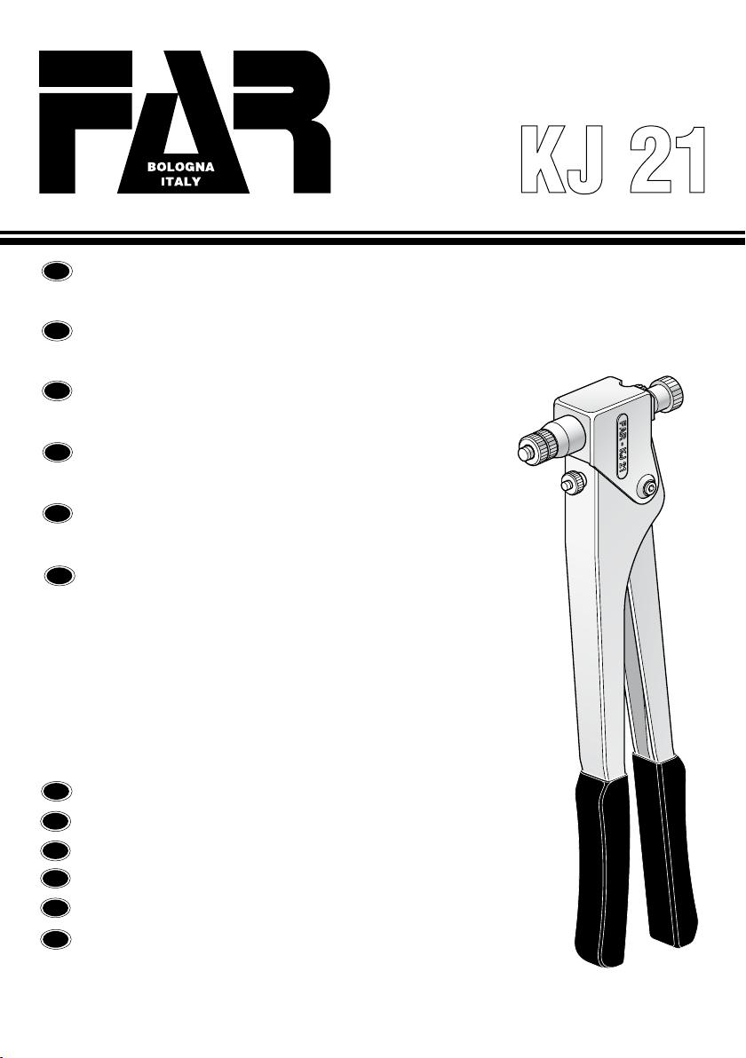
Vor Gebrauch, nachsehen ob die zwei Teile Zugbolze-Kopf, die auf dem Werkzeug montiert sind, zur Blindnietmutter-Gewinde, die
man klemmen will, passen. Wenn es nicht den Fall ist, muss man den richtigen Durchmesser auswählen.
ACHTUNG: Normalerweise ist das Paar “Zugbolze-Kopf” auf dem Werkzeug in M8 montiert.
DURCHMESSERWECHSEL:
Kopf (1) und Ansatz (2) abschrauben.
Die Schraube (3) lockern und den Zugbolzen (4) wegnehmen; der Zugbolzen wird gewechselt in dem man die richtige Dimension
aus dem Kit heraus nimmt.
Alle Werkzeuge sind mit Zugbolzen und Köpfe von jedem Durchmesser geliefert. Den Ansatz (2) ist für alle Grössen verwendbar.
Bei Zugbolzen M3, M4, M5 und M6, ist es möglich der alleine Dübel (5) auszuwechseln, indem er aus dem entsprechen den Bolzen
entfernt wird. Mittels eines Sechskantschlüssels den neuen Dübel in seinen Sitz anschrauben und mit Hilfe von Loctite für Gewinde
befestigen.
KURSUSREGULIERUNG:
Regulierschraube (6) lockern für den Kursus steigern und schrauben um ihn verkleinern.
Wenn man den Kursus steigert, erträgt die Blindnietmutter eine grössere Verzerrung und die Distanz (h) zwischen dem Kopf der
Blindnietmutter und seine Verzerrung erträgt eine Quatschung.
Im Gegenteil, wenn man den Kursus reduziert, wird die Distanz (h) grösser wegen der unteren Verzerrung.
Wenn die Vorregulierung eingestellt ist, muss man die Blindnietmutter auf das Stück setzen und Kursus anpassen in dem man
den Kursus von der Blindnietmutter mit der Dicke kontrolliert.
Im Falle der Kursus reduziert ist, riskiert man eine schlechte Blockierung; im Gegenteil, d.h. wenn der Kursus zu gross ist, riskiert
man eine Gewinde-verzerrung.
KOPF EINSTELLUNG:
Nach der Kursus-Einstellung kann man den Kopf einstellen.
Die Blindnietmutter auf den Zugbolzen schrauben bis Kontakt mit dem Kopf des Werkzeuges.
Prüfen dass der Zugbolze von 0,5 mm aus der Blindnietmutter rausschaut; wenn es nicht den Fall ist, den Ansatz (2) deblockie-
ren. Dann die Kopfstellung einstellen per Schraubung für steigern, oder abschrauben für verringern um den Zugbolze heraus zu
machen. Nach diesem Vorgang, den Ansatz blockieren (2).
Dieser Vorgang muss immer wiederholt werden wenn Grösse oder Länge von Blindnietmutter gewechselt werden.
BLINDNIETMUTTERKLEMMUNG:
Nachdem man die Blindnietmutter auf den Zugbolzen geschraubt hat, muss man die Blindnietmutter in das gebohrenes Loch
einlegen und den Hebel (7) pressen. Am Ende diesem Vorgang, den Zugbolzen abschrauben. Das Werkzeug ist für eine neue
Blindnietmutter zur Schraubung parat.
NITOWNICA RĘCZNA DO UŻYTKU Z NITONAKRĘTKAMI GWINTOWANYMI Z GWINTEM OD M3 DO M8.
Przed użyciem należy upewnić się, czy trzpien i głowica zamontowane na nitownicy są odpowiednie do gwintu nitonakrętki, którą chce się zacisnąć, w przeciwnym
wypadku, należy przeprowadzić zmianę formatu.
Uwaga: Zazwyczaj trzpien i głowica zamontowane na nitownicy w opakowaniu odpowiadają gwintowi M8.
ZMIANA FORMATU:
Odkręcić i zdjąć głowicę (1) oraz nasadkę pierścieniową (2).
Poluzować śrubę (3) i wyjąć trzpien (4); wymienić je, wybierając z dostarczonego zestawu odpowiedni rozmiar. Każda nitownica jest wyposażona w osobne trzpien i
głowicę dla każdego formatu nitonakrętki, zaś nasadka pierścieniowa (2) jest odpowiednia do wszystkich formatów. W przypadku cięgien M3, M4, M5 i M6, możliwa jest
wymiana wyłącznie części gwintowanej (5), którą wyjmuje się ze sworznia. Należy przykręcić nową część gwintowaną w gnieździe kluczem sześciokątnym, blokując ją
przy użyciu środka Loctite zabezpieczającego gwinty.
REGULACJA SKOKU:
Tę operację należy przeprowadzić przed zastosowaniem nitonakrętki, na podstawie grubości materiału, który chce się połączyć.
Regulację przeprowadza się przy użyciu pokrętła regulacyjnego (6), odkręcając je w celu zwiększenia skoku i przykręcając w celu zmniejszenia go.
Zwiększając skok uzyskuje się większe odkształcenie nitonakrętki i, wynikające z tego, zmniejszenie odległości (h) między główką nitonakrętki a zniekształceniem.
Zmniejszając zaś skok, odległość (h) zwiększy się z powodu mniejszego odkształcenia.
Po przeprowadzeniu wstępnej regulacji, zamocować nitonakrętkę na materiale i dokończyć regulacji na podstawie tego, jak nitonakrętka zaciska się na materiale.
Optymalny skok to taki, który umożliwia solidne, ale nie nadmierne zaciśnięcie nitonakrętki na materiale: w przypadku zbyt małego skoku, może mieć miejsce
niedostateczne zablokowanie nitonakrętki; w przypadku zbyt dużego skoku, ryzykuje się zniekształcenie gwintu.
REGULACJA GŁOWICY:
Po określeniu skoku, należy wyregulować głowicę (1) nitownicy w taki sposób, aby trzpien chwytało cały gwint nitonakrętki.
Przykręcić na cięgnie gwintowaną nitonakrętkę, tak aby jej główka była dociśnięta do głowicy nitownicy.
Upewnić się, że trzpien wychodzi na ok. 0,5 mm z nitonakrętki; w przeciwnym wypadku odblokować nasadkę pierścieniową (2) i wyregulować położenie głowicy: dokręcając
ją, trzpien będzie bardziej wystawało; odkręcając, trzpien schowa się; po zakończeniu operacji zablokować nasadkę (2).
Powyższe czynności regulacyjne muszą być powtarzane przy każdej zmianie formatu.
ZACISKANIE NITONAKRĘTKI:
Wkręcić nitonakrętkę na trzpien, umieścić ją w otworze wykonanym w materiale i zacisnąć przy użyciu dźwigni (7).
Po zakończeniu operacji wykręcić trzpien: nitownica jest gotowa do zaciśnięcia nowej nitonakrętki.
Polski

1
3
26
27
19
15
20
31
4
2
1
32
30
8
28
24
9
14
10 11 12 13 25
29
7 A
6 A
5
32
KIT A
7A(x1)
6A(x1)
17
22
18
23
16
21
KIT A
742302 1 Kit perno Pin kit Jeu pivot Stiftsatz Zestaw sworznia
6 713068 1 Molla ritorno leva Lever return spring Ressort retour levier Feder Rücklauf Hebel Sprężyna powrotna dźwigni
7 712302 1 Perno filettato Threaded pin Pivot filete Gewindestift Sworzeń gwintowany
KIT
Indica che il particolare
viene venduto in Kit
composti da particolari
diversi in quantità
diverse.
It indicates that the part is sold
in kits consisting of different
parts in different quantities.
Indique que la pièce est
vendue dans des KITS
composés de diverses
pièces dans des quantités
différentes.
Dieses Wort gibt an, daß der Teil
in KIT von verschiedenen Teilen in
unterschiedlichen Mengen verkauft
wird.
Oznacza, że dany detal jest
sprzedawany w Zestawach złożonych
z różnych detali w różnych ilościach.
N° COD. Qt. DESCRIZIONE DESCRIPTION DESCRIPTION BESCHREIBUNG
OPIS
KIT
1 712907 2 Manopola Handle Poignée Griff Pokrętło
2 712301 1 Leva secondaria Secondary lever Levier secondaire Zweithebel Dźwignia pomocnicza
3 712300 1 Leva principale Principal lever Levier principal Haupthebel Dźwignia główna
4 712304 1 Biella Connecting rod Bielle Umlenkhebel Złącze
5 712310 2 Leva Lever Levier Hebel Dźwignia
6 713068 1 Molla ritorno leva Lever return spring Ressort retour levier Feder Rücklauf Hebel Sprężyna powrotna dźwigni A
7 712302 1 Perno lettato Threaded pin Pivot lete Gewindestift Sworzeń gwintowany A
8 710149 1 Pomello Knob Bouton Knopf Pokrętło
9 711772 1 Ghiera Ring nut Embout Nutmutter Nasadka pierścieniowa
10 713085 1 Testina M3 Head M3 Tête M3 Kopfteil M3 Głowica M3
11 713086 1 Testina M4 Head M4 Tête M4 Kopfteil M4 Głowica M4
12 713087 1 Testina M5 Head M5 Tête M5 Kopfteil M5 Głowica M5
13 713088 1 Testina M6 Head M6 Tête M6 Kopfteil M6 Głowica M6
14 713089 1 Testina M8 Head M8 Tête M8 Kopfteil M8 Głowica M8
15 723062 1 Tirante M3 Tie rod M3 Tirant M3 Zugbolzen M3 Trzpien M3
16 723063 1 Tirante M4 Tie rod M4 Tirant M4 Zugbolzen M4 Trzpien M4
17 723064 1 Tirante M5 Tie rod M5 Tirant M5 Zugbolzen M5 Trzpien M5
18 723065 1 Tirante M6 Tie rod M6 Tirant M6 Zugbolzen M6 Trzpien M6
19 723066 1 Tirante M8 Tie rod M8 Tirant M8 Zugbolzen M8 Trzpien M8
20 713080 1 Vite STCE M3x30 UNI 5923 Screw STCE M3x30 UNI 5923 Vis STCE M3x30 UNI 5923 Schraube STCE M3x30 UNI 5923 Śruba STCE M3x30 UNI 5923
21 713081 1 Vite STCE M4x35 UNI 5923 Screw STCE M4x35 UNI 5923 Vis STCE M4x35 UNI 5923 Schraube STCE M4x35 UNI 5923 Śruba STCE M4x35 UNI 5923
22 711625 1 Vite STCE M5x35 UNI 5923 Screw STCE M5x35 UNI 5923 Vis STCE M5x35 UNI 5923 Schraube STCE M5x35 UNI 5923 Śruba STCE M5x35 UNI 5923
23 713083 1 Vite STCE M6x40 UNI 5923 Screw STCE M6x40 UNI 5923 Vis STCE M6x40 UNI 5923 Schraube STCE M6x40 UNI 5923 Śruba STCE M6x40 UNI 5923
24 713070 1 Cufa di protezione Protecting cap Protecteur Schutzkappe Osłona
25 712305 1 Corpo interno Inside body Corps intérieur Innenschaft Korpus wewnętrzny
26 710137 1 Vite TCI M5 x 5,3 Screw TCI M5 x 5,3 Vis TCI M5 x 5,3 Schraube TCI M5 x 5,3 Śruba TCI M5 x 5,3
27 712303 1 Perno Pin Pivot Stift Sworzeń
28 713084 2 Vite M4 x 8 ISO 7380 Screw M4 x 8 ISO 7380 Vis M4 x 8 ISO 7380
Schraube
M4 x 8 ISO 7380
Śruba
M4 x 8 ISO 7380
29 713079 1 Perno lungo Long pin Pivot long Langer Stift Śruba wypukła
30 713095 1 Spina elastica ø 4 x 18 Spring pin ø 4 x 18 Goupille élastique ø 4 x 18 Spannstift ø 4 x 18 Wtyczka elastyczna ø 4 x 18
31 713067 1 Perno lungo lettato Long threaded pin Pivot leté long Langer Gewindestift Sworzeń długi gwintowany
32 713061 2 Perno corto Short pin Pivot court Kurzer Stift Sworzeń krótki
KIT
PARTI DI RICAMBIO • SPARE PARTS • PIECES DETACHEES • ERSATZTEILE •
CZĘŚCI ZAMIENNE


Date 02-2011 Revision - 02
L’elenco dei centri di assistenza è disponibile sul Ns. sito
web: http://www.far.bo.it ( Organizzazione )
The list of the service centres is available on our website
http://www.far.bo.it ( Organization )
La liste des centres d’assistance est disponible sur notre
site internet http://www.far.bo.it ( Organisation )
Die Liste der Reparaturservices ist verfügbar unter unserer
Webseite http://www.far.bo.it ( Organisation )
La lista de los servicios postventa es disponible en nuestro
sitio web http://www.far.bo.it ( Organización )
Lista punktów serwisowych jest dostępna na naszej stronie internetowej
http://www.far.bo.it ( Organizacja )
I
F
E
PL
GB
D
SISTEMI DI FISSAGGIO
FASTENING SYSTEMS • SYSTEMES DE FIXATION
VERBINDUNGSSYSTEME • SISTEMAS DE FIJACION
SYSTEMY MOCOWANIA • СИСТЕМЫ КРЕПЛЕНИЯ
www.far.bo.it
SEDE • HEAD OFFICE • SIEGE
HAUPTSITZ • SEDE
SIEDZIBA • ОФИСНЫЙ ЦЕНТР :
40057 Quarto Inferiore - Bologna - Italy
Via Giovanni XXIII, 2
Tel. +39 - 051 6009511
Ufficio Vendite Fax +39 - 051 767443
E-mail: itacom@far.bo.it
Export Dpt. Fax +39 - 051 768284
E-mail: export@far.bo.it
DEPOSITO • WAREHOUSE • DEPOT
WARENLAGER • ALMACEN
ODDZIAŁ • СКЛАД :
20099 Sesto San Giovanni
Milano
Italy
Via Archimede, 8
Tel. +39 - 02 2409634
Fax +39 - 02 26222279
E-mail: itacom@far.bo.it
Table of contents
Other FAR Tools manuals