manuals.online logo
Brands
  1. Home
  2. •
  3. Brands
  4. •
  5. Farfisa
  6. •
  7. Intercom System
  8. •
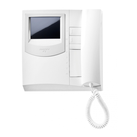
  9. Farfisa PROJECT Series User manual

Farfisa PROJECT Series User manual

TECHNICAL
MANUAL
2004
ALTERNATE
CURRENT
CALL SYSTEMS
INTRODUCTION
Thiseditioncontainshelpfulinformationontheoperationandinstalla-
tionofFarfisavideointercomssystems.
Inordertomakethesystemsworkproperlyitisnecessarytoinstallonly
Farfisa equipment, keeping strictly to the items referred to in each
diagram.
Readallthenotescarefully,(eventhesmallones)ineachinstallation
scheme and the working instructions of the system given in the
followingpages.
Forthesakeofclarity,pleasenoticethatthesequenceoftheterminals
ofeacharticlehasnotbeenfollowed.Onlytheterminalcode(letterand/
ornumber)isvalidnotthegraphicsequence.
Theitems mayhave moreterminals thanthe onesin theinstallation
diagrams.Theexcessterminalsmustnotbeused.
ItalianAssociationofElectrotechnicaland
ElectronicIndustries
Mark of VDE a German Testing and Certi-
ficationInstitute.
Qualityassuredfirm.
Notice to the installer and user
Checktheintegrityoftheproductafterremovingitfromthepacking.
Packing materials (such as plastic bags, cardboard, polystyrene
foam,etc.)mustbekept outofthereachofchildren.
Themanufacturercannotbeheldresponsibleforpossibledamages
causedbyimproper,erroneousandunreasonableuse.
The cable runs of any intercom and video-intercom system must be
kept separate from the mains or any other electrical installation as
required by International Safety Standards.
WARNINGS
An all-pole mains switch with a contact separation of at least
3mmineachpoleshallbeincorporatedintheelectricalinstalla-
tion of the building.
Before connecting the unit, make sure its data correspond to
those of the mains.
The apparatus shall not be exposed to dripping or splashing.
Forcorrectoperationmakesurethatventilationorheatdissipa-
tion openings are not obstructed.
Do not open or tamper with power supply or video intercom
apparatus when they are ON. There is high voltage inside.
Avoid bumping and hitting the video intercom apparatus, it
could break of the CRT with consequent projections of frag-
mented glass.
For installation or maintenance refer only to qualified person-
nel.
CEMARK
The CE mark ensures that the product complies with the requirements of the
European Community Directives in force; in particular, Electrical Safety LVD73/23,
Electromagnetic Compatibility EMC89/336 and Telecommunication Terminals
R&TTE99/5 Directives.
As set forth by the Directives, the technical documentation and Conformity Decla-
rations are available in the Company’s offices for verifications and controls by
competent Authorities.
EuropeanMarkofconformitytotheEEC
Directives.
SGS
I
S
O
9
0
0
1
:
2
0
0
0
S
Y
S
T
E
M
C
E
R
T
I
F
I
C
A
T
I
O
N
1
(MT12 - Gb2004)
INDEX
Installation instructions
Intercoms
- Internal stations
- External door stations
- Power supplies
- Service modules
- Installation instructions
- Installation diagrams
Video Intercoms
- Internal stations
- External door stations
- Power supplies, control units and service modules
- Installation instructions
- Installation diagrams
Telecommunication
- Internal stations
- Intercom-telephone interface
- Electronic PABX
- Installation instructions
- Installation diagrams
Product List
TECHNICALMANUAL
2004 edition
12
Page
2
3
4
7
24
25
26
29
71
72
81
90
91
95
149
150
162
164
170
173
192
2
(MT12 - Gb2004)
TheFarfisaalternatecallsystemallowsforthe
realisationofintercom,videointercom,digital
andintercom-telephonesystems.
The modularity of Farfisa indoor and outdoor
devicesallowsforsystemextensiontosatisfy
the most diverse user’s requirements, from
individualhousestoapartmentbuildings,from
simpleintercomstocompletevideointercom-
telephonesets.
Selecting the system
TheFarfisaalternatecallsystemallowsforthe
realisationofdifferenttypesofinstallation.
• Intercomsystems
• Videointercomsystems
• Intercom-telephonesystems
• Videointercomsystems
• Mixed systems (intercom/video intercom/
telephone)
Intercom systems
Itisthesimplestoftheinstallations. Itprovides
bidirectional audio communication between
intercomsandexternaldoorstationswithdoor-
openingfunction.Thefollowingvariantsofthe
basicinstallation are possible:
-intercommunicating service. It allows for
communicationbetweendifferentintercoms
of the same apartment or between different
apartmentswithprivateconversationtoother
usersandtoexternalstations.
-privateconversation.Byaddingaboardto
eachintercomyoucanrestrictthecommuni-
cationbetween internal and external user to
the called user. The other users do not hear
theconversationinprogresswhentheyliftthe
handset.
Fortherealisationofabasicintercomsystem
youneed4 common wires+ 1 singlefor each
user.
Video intercom systems
Apart from audio communication and door-
openingfunction,videointercomsystemspro-
videvisualcontroloftheentrance.Thetypical
characteristicsofvideointercomsystemsare:
-Timedoperation.Thevideointercomofthe
calleduserisenabledfor about 40 seconds.
Thetimedoubles if the handsetislifted.The
systemreturnstothestand-bystatewhenthe
handsetisreplaced.
-Private conversation. Video intercom sys-
temsallow for audio communicationonly for
the called user. The other users do not hear
theconversationinprogresswhentheyliftthe
handset.
-Intercommunicating service. This service
allowsforaudiocommunicationbetweendif-
ferent intercoms or video intercoms of the
same apartment or between different apart-
mentswithprivateconversationtootherusers
orexternalstations.
-ControlswitchingON.Theusercanenable
thesystem,switchONhis/herownvideointer-
comandmonitortheareaframedbythecam-
era. Additional wires and activation buttons
areneededincaseofmultipleentrances.
INSTALLATION INSTRUCTIONS
I
NTERCOMS *
V
IDEOINTERCOMS *
T
ELECOMMUNICATION
For the realisation of basic video intercom
systemsyouneed7commonwires+1single
foreachuser+commoncoaxialcable.
Intercom-telephone and video intercom-
telephone systems
Itisavariantoftraditional intercom and video
intercomsystemsinwhichinternalstationsuse
telephones(withmonitorsforvideointercom-
telephone functions) instead of intercoms or
videointercoms.Inthiscaseintercomconnec-
tions are established over an interface board
thatprovidestelephoneandintercomcommu-
nication. The interface can be a stand alone
product (art. FT11D) or an interface board to
be installed inside the FT105P or FT208P
electronic PABX (art. ES60 or ES65).
Internalstationscanuse:
-astandardtelephoneinwhichintercomfunc-
tions are obtained by dialling specific codes
onthekeypad
-an intercom-telephone set (art.ST740) or
video intercom-telephone set (art.ST740 +
ST7100) with telephone functions and spe-
cificbuttonsforthemainintercomservices.
In intercom-telephone systems the intercom-
municatingservicecanbe realized by means
ofa PABX thatallowsalso for privateconver-
sation.
Intercom-telephonesystemsneed4common
wires + 1 single for each user (+ 3 common
wires+commoncoaxialcableortwistedpairin
caseofvideointercom-telephonesystems)for
connections to the riser. Telephone connec-
tionsare made witha telephone pair.
Mixed systems (intercom/intercom-tele-
phone/video intercom-telephone)
All intercom, intercom-telephone and video
intercom-telephonesystemscanbecombined
accordingtotheuser’srequirements.
Choosing the correct article
Whenchoosingthearticleandtypeofinstal-
lation,youshouldconsider:
• user’srequirements
• numberofusers
• installationpossibilities
• possiblelocation ofarticles.
Thefollowingoptionsarepossibleforexternal
door stations:
•Mody series push-button panels for inter-
com, telephone and video intercom sys-
tems
•Matrix series stainless steel push-button
panels for intercom, telephone and video
intercomsystems
•Prestige series brass push-button panels
forintercom,telephoneandvideointercom
systems
•ErreP/Rseriespush-buttonpanelsforinter-
comandtelephonesystems
•TM seriespush-buttonpanelsforintercom
andtelephonesystems
•UPseriespush-buttonpanelsforanalogue
intercomandtelephonesystemswithmaxi-
mum2calls
Thefollowingoptionsarepossibleforinternal
stations:
•Studiomodularlineforintercom-telephone
andvideointercom-telephonesystems
•Projectlineforintercomandvideointercom
systems
•PuntoVirgolaforintercomandvideointer-
comsystems
•Slim(900)lineforintercomsystems
Speaker
Microphone
Button
Resistance
Lamp
Optionalwire(usuallycontrolswitch-
ing ON, door release button or inter-
communicatingcalls)
Dashedline(forschematicpurposes
thefirstandlastmonitorsareshownin
the multi-family systems. Required
additionalmonitorscanbeinsertedin
such dashed line to complete the in-
stallation).
Diode
Electronicringerorbuzzer
Coaxial cable
xn
x2 Callwires(secondandlast)
Telephonepair
Electric door lock
Graphicsymbols
Thefollowingsymbolsareusedintheinstalla-
tiondiagrams:
Mechanicalbuzzer
3
(MT12 - Gb2004)
INTERCOMS
Technicalmanual12 Edition 2004
INDEX
Internalstations
-Projectseriesintercoms
-PuntoVirgolaseriesintercoms
-Slim(900)seriesintercoms
Externaldoorstations
-Modyseriespush-buttonpanels
-Matrixseriespush-buttonpanels
-ErreP/Rseriespush-buttonpanels
-UPseriespush-buttonpanels
Powersupplies
Servicemodules
Installationinstructions
Workinginstructions
Troubleshooting
Basicinstallationdiagrams
-Si11MO/1 Intercomsconnectedto1externaldoorstation
-Si11MO/2 Intercomswithprivateconversationconnectedto1externaldoorstation
-Si12MO/1 Intercomsconnectedto2automaticallyswitchedexternaldoorstations
-Si13MO/1 Intercomsconnectedto3automaticallyswitchedexternaldoorstations
-Si16MO/1 Intercomsystemwithsecondarydoorstationsand1maincommonstation(multipleentrance)
-Si16MO/2 One-wayintercomsystemwithsecondarydoorstationsand1maincommonstation(multipleentrance)
-Si17MO/1 Intercomsystemwithsecondarydoorstationsand2maincommonstations(multipleentrance)
Intercommunicatinginstallationdiagrams
-Si100L/2 2intercommunicatingintercoms
-Si100L/11 Intercommunicatingintercoms(2to11users)
-Si115L/5S 5intercommunicatingintercomsconnectedto1externaldoorstationwithsinglecalls. Electronicbellforinternalcalls.
-Si111L/5M 5intercommunicatingintercomsconnectedto1externaldoorstationwithcommoncall.Electronicbellforinternalcalls.
-Si125L/5S 5intercommunicatingintercomsconnectedto2externaldoorstationswithsinglecalls. Electronicbellforinternalcalls.
-Si121L/5M 5intercommunicatingintercomsconnectedto2externaldoorstationswithcommoncall.Electronicbellforinternal
calls.
-Si135L/5S 5intercommunicatingintercomsconnectedto3externaldoorstationswithsinglecalls. Electronicbellforinternalcalls.
-Si131L/5M 5intercommunicatingintercomsconnectedto3externaldoorstationswithcommoncall.Electronicbellforinternal
calls.
-Si161L/1S One-wayintercommunicatingsystemwithsecondarydoorstationsand1maincommonstation(multipleentrance)
-Si11MO/3 Multi-wayintercomsystemconnectedto1externaldoorstation.Withintercommunicationservicein1ormore
apartmentsandprivateconversationfeaturewiththeexternaldoorstationandtheotherapartments.
Applicationdiagrams
-multi-wayintercommunicatingservices
-one-wayintercommunicatingservices
-one-wayintercommunicatingservicesinapartmentbuildingsystems
Page
4
4
6
6
7
7
16
22
23
24
25
26
27
28
29
31
33
35
37
39
41
43
44
45
45
47
49
51
53
55
57
59
61
62
62
66
68
I
NTERCOMS *
V
IDEOINTERCOMS *
T
ELECOMMUNICATION
4
(MT12 - Gb2004)
I
NTERCOMS *
V
IDEOINTERCOMS *
T
ELECOMMUNICATION
PT520. Two-colourintercomfor4+1systems
connectedtooneormoredoorstations.Com-
pletewithbuzzer,spiralcord,electronicmicro-
phone and two push-buttons that can be in-
creased to 10 by adding the individual push-
buttonunit,art.PT501.Itcanbeinstalledonthe
wallwithscrews or onaback box.
PT520W. Colour:white.
Terminals
1microphone
2loudspeaker
3ground
5door release push-button (max 1A)
6buzzer (0.2A)
7common push-buttons ( and 1)
9electronic bell input
P1 service push-button (max 1A)
P2 ÷ P9 service push-buttons (max 0.5A)
INTERNAL STATIONS
INTERCOMS PROJECT series
Fittings for PT520 and PT520W intercoms
PT501. Individual push-button unit.
Note
WerecommendtoinserttheLED module PT502
and bell silencer module PT515 in the bottom 2
slots marked by and .
To insert them properly it's necessary to remove
theguideofthebuttonslidingfromtheinternalside
of the base cover (see figure).
PT502. Led module.
PT515. Bell silencer module (privacy).
P2
P7
P9
P8
2
W1
1
7
L+
L-
RL36. Relaymodule.Wheninstalledinside
intercomsit allowsto activate additional bells
(see page 27). Maximum switching current is
1A (24V).
Terminals
Ccommon terminal of relay
NA normally open contact of relay
NC normally closed contact of relay
-ground
13Vac/dcvoltageinput
EC relay activation input (ground command)
Wires
9electronic call input without resistive load
3ground
ONOFF
PT515
63
L-
L+
call push-
button
intercom
P
R
O
J
E
C
T
3
"
8
/
3
2
8
"
"
16
16
/
/
13
1
8672
214
5
(MT12 - Gb2004)
I
NTERCOMS *
V
IDEOINTERCOMS *
T
ELECOMMUNICATION
INTERNAL STATIONS
INTERCOMS PROJECT series
2136
2916357
C
B
9
X2
7
X1 9
PT510. Two-colourintercomfor4+1systems
connectedtooneormoredoorstations.Com-
pletewithpush-button,spiralcord,buzzer,elec-
tronicmicrophone.Wall-mountedwithscrews
or fixed to back box.
PT510N. Colour: beige.
PT510W. Colour:white.
PT524W. Whitecolour finishwith carbon mi-
crophone.
Terminals
1microphone
2loudspeaker
3ground
5door release push-button (max 1A)
6buzzer (0.2A)
9electronic bell input
Two of the following
modules can be si-
multaneouslyapplied
inside the intercoms:
-RL36 relay module;
-SM50 private con-
versation module;
-SR40electronicbell
module;
-SR41 electronic
buzzer module.
6
W1
291 357
+
-
97
SR40. Electronic bell module (see inter-
communicationdiagrams).
Terminals
power supply call in-
put(12Vac-0.5A)
X1 power supply input
(12Vac-0.3A)
X2 callinput(groundcon-
trol)
SR41. Electronic buzzer module. It can be
used to differentiate calls from external door
stationsorexternaldoorstationand
intercommunicatingstations(inthis
case it can replace electronic bell
moduleSR40).
Terminals
4power supply input (13Vac-70mA;
9÷20Vdc-15mA)
3ground
SM50. Private conversation module (see
pages 32 and 100).
Terminals
Caudio line receiver
Baudio line transmitter
- ground
PT538. Table adapter for Project series in-
tercoms,withweightedbase,junctionboxand
2.4mconnectioncablewith13wires.
RL36
or
SM50
or
SR40
or
SR41
PT501
PT502
PT515
2136
C
B
SM 50
R1
10K
9 7
2315P16
X2
7
X1 9
PT501
43
P
R
O
J
E
C
T
6
(MT12 - Gb2004)
I
NTERCOMS *
V
IDEOINTERCOMS *
T
ELECOMMUNICATION
INTERNAL STATIONS
INTERCOMS PuntoVirgola series
2"
8
/
3
60
1"
8
/
7
48
8"
8
/
7
225
1"
16
/
13
46
2"
8
/
5
66
8"
8
/
7
225
924W. Beige intercom for 4+1 systems con-
nected to 1 or more door stations. Complete
with a push-button, spiral cord, electronic mi-
crophone,buzzer.
Itcanbeinstalledonthewallwithscrews.
Terminals
1Microphone
2Loudspeaker
3Ground
5Door release push-button (1A max)
6Buzzer (0.2A)
9Electronic bell input (from PRS240 or digital
systems)
910W. Open-voice,white, two-way model for
4+1 systems connected to one or more door
stations,withinternalamplificationandmodu-
latedelectronicbellandknobforadjustingthe
volume(receivingchannel).Thismodelispro-
videdwithtwopush-buttons(oneforconnect-
ing the audio line and the other one for the
electricdoorlock).Tooptimisespeechquality
the use of 337C electric speaker is recom-
mended. It can be installed on the wall with
screwsoronawallbox.
Terminals
The same of 924 series.
3
"
4
/
1
83
2
"
8
/
3
60
3
"
4
/
1
83
6
"
16
/
9
166
5
6
3192
PV100. Two-colourintercomfor4+1systems
connectedtooneormoredoorstations.Com-
plete with a push-button, spiral cord, built-in
electronic bell, electronic microphone. Wall-
mountedwithscrewsorfixedtobackbox.
PV100W. Colour:white.
Terminals
1Microphone
2Loudspeaker
3Ground
5Door release push-button (1A max)
6Buzzer (0.35A)
9Electronic bell input
921653
205
53
128
5"
16
/
1
32 ""
1616
//
11
8"
16
/
1
78
INTERCOMS 900 series (Slim) OPEN VOICE 900 series
P
V
-
9
0
0
7
(MT12 - Gb2004)
Push-buttonpanelsinextrudedaluminiummadeup
ofmodularelements.Suitableforthemostdiverse
installationrequirements.
MD71.72.73.74.Plasticbackboxescompletewith
moduleframes.
MD81.82.83.804.84.86.808.89.812. Aluminium
hoodcovers.TobeaddedtoMD71.72.73.74back
boxes.
MD91.92.93.904.94.96.908.99.912. Anodized
aluminiumrainshelterswith module frames. Used
forwallmounting.
MD 71 MD 72 MD 73 MD 74
MD 81 MD 83 MD 804MD 82 MD 86 MD 808MD 84
MD 904MD 93MD 92MD 91
Rain shelters with module frames
Hood covers
Module frames complete with back box
PUSH-BUTTONS MODY series
EXTERNAL DOOR STATIONS
MD 94 MD 96 MD 908 MD 99 MD 912
I
NTERCOMS *
V
IDEOINTERCOMS *
T
ELECOMMUNICATION
M
O
D
Y
MD 812MD 89
8
"
8
/
3
64
19
124
304.5
395
213
121.5
4
"
16
/
13
12
"
15
"
16
/
9
4
"
8
/
7
2
"
2
/
1
"
4
/
3
9"
8
/
1
12
16
"
"
16
16
/
/
11
5
151
5"
16
/
15
5"
2
/
1
323
414.5
140
231.5
276
10
"
8
/
7
1
"
16
/
9
1
"
401
15
"
16
/
13
40
25
12
16
"
"
16
16
/
/
11
5
323
414.5
323
414.5
231.5 9
"
8
/
1
12
16
"
"
16
16
/
/
11
5
151
5
"
16
/
15
5
"
2
/
1
140
3
"
8
/
1
80
2
"
16
/
9
65
401
15
"
16
/
13
276
231.5
323
414.5
10 "
8
/
7
16 "
16
/
5
12 "
16
/
11
9"
8
/
1
8
(MT12 - Gb2004)
PUSH-BUTTONS MODY series
In any button module, in order to avoid the
dismountingofnameholder,inserta3MAx12
screwintheholesshowninthepictureforeach
name plate to be blocked. Screws are not
suppliedbythemanufacturer.
Dismounting of name holder to insert name
label.
MD 10
without call buttons MD 11
1 call button MD 12
2 call buttons
1 row push-button modules
Modules for electric door speaker (amplifier)
Button modules
MD 22
2 call buttons MD 24
4 call buttons
MD 23
3 call buttons
MD 21
1 call button
2 row push-button modules
MD 122
2 call buttons MD 124
4 call buttons
ELECTRIC DOOR SPEAKER
MD 30.
It consists of a double amplifier (receiver and
transmitter)withadjustablevolumeof2chan-
nels. Also fittable to Prestige and ErreP/R
series push-button panels (for ErreP/R door
stationsbymeansof 299/1 adapter).
Terminals
1audio receiver
2audio transmitter
3positive power supply 6 ÷ 8Vdc - 60mA
4ground
Dismountingandprotectionofnamela-
bels
MD 222
2 call buttons MD 224
4 call buttons MD 226
6 call buttons MD 228
8 call buttons
MD20
blankmodule
Modules: blank, number, access control and cameras
2
8
5
0
3
9
B
6
1
7
A
4
FC52P. Keypad
module for access
control (see page 9).
MD50
number module
50
MD41. MD41D. Black
and white cameras.
MD41C.Colourcameras
(see characteristics on
page 81).
Button modules
Modules for electric door speaker (amplifier) Receiving volume adjustment
Transmitting volume
adjustment
EXTERNAL DOOR STATIONS
I
NTERCOMS *
V
IDEOINTERCOMS *
T
ELECOMMUNICATION
M
O
D
YFP52. Proximity
readerforaccesscon-
trol (see page 9).
MD 100
Amplified door sta-
tionwith 1push-but-
ton (see page 9)
MD 200
Amplified door sta-
tionwith 2push-but-
tons (see page 9)
3
"
16
/
9
91
1
"
25.5
2
"
16
/
3
55
9
(MT12 - Gb2004)
I
NTERCOMS *
V
IDEOINTERCOMS *
T
ELECOMMUNICATION
M
O
D
Y
12
1 2
AMPLIFIED DOOR STATIONS
MD 100. 1 button module.
Fittableinallintercom,telephone,intercommu-
nicatingandvideointercomsystems.
Completewithelectricdoorspeakeramplified
in the two channels, receiving adjustable vol-
ume,callbuttonandanodizedaluminiumfront
plate.ItcanreplacetheMD11andMD30mod-
ule and use all the other accessories of the
Mody series.
MD 200. 2 buttons module.
Terminals
-ground
supply 13Vac - 0.13A
1audio receiver
2audio transmitter
Ccall push-buttons common
call push-buttons
name-plate lamp (24V-70mA)
1Lamp terminals
2Push-button terminal board
3Common contact of call push-buttons
4Terminals on stair light push-button
5External volume adjustment
6Terminal board for connection to the system
2
3
4
5
6
1
ACCESS CONTROL KEYPAD
FC52P.
Access control keypad with 12 keys and 2
relays for lock release. 4 programmable ac-
cesscodesforeachrelay.Programmabledoor
openingtime from 1 up 99 sec. foreach relay
(orbistableoperationofrelay1).Acousticand
visualconfirmationforenteredkeys,accepted
programmingandforwrongcodes.
Technical data
Power supply: 12Vac/dc±10%
Stand-by current: 0.015A
Maximum current consumption: 0.1A
Contact ratings: 12Vac-5A
Numbers of codes for relays 1: 4
Numbers of codes for relays 2: 4 or direct
activation
Activation time for each relay: from 1 to 99sec.
(or bistable relay 1)
Operating temperature: 0° ÷ +40°C
Maximum permissible humidity: 85% RH
Terminals
1normally closed contact of relays 2
2normally open contact of relays 2
3common contact of relays 2
4normally closed contact of relays 1
5normally open contact of relays 1
6common contact of relays 1
7ground or alternate voltage input
8positive or alternate voltage input
9-10 connection to optional door lock release
Example of composition
PUSH-BUTTONS MODY series
EXTERNAL DOOR STATIONS
Installationdiagrams
For the installation of the MD100 and MD200
modulesseetheinstallationdiagramsforsys-
tems with one entrance in the “intercom” and
“video intercom” section (for example pages
30, 32, 46, 48, 98, 102, 120, 178 and 180).
10987654321
10987654321
12Vac
12Vdc
door
release relay 1 relay 2
PROXIMITY READER FOR ACCESS
CONTROL
FP52.
Thisarticleallowsfortheactivationof2relays
by means of keytags or electronic ISO cards
basedontranspondertechnology.
Programmable activation time from 1 to 63
seconds for every relay. 4 user cards and 1
mastercardsuppliedwiththeproduct.Acoustic
andvisualcontrolsignalsand3-digitdisplayto
view numbers and codes during set-up and
operation.
Technical data
Power supply 12Vac/dc ±10%
Stand-by current 0.1A
Maximum current consumption 0.25A
Contact ratings 24Vac - 2A
Max. number of cards 490
Max. number of Master cards 10
Number of relays 2
Relay time 1 to 63 sec.
Minimum recognition distance 3 cm
Maximum recognition time 1 sec.
Operating temperature 0° ÷ +40°C
Maximum permitted humidity 85% RH
Terminals
+/A positive or alternate current input
-/A ground or alternate current input
PB door open button
NC2 normally closed contact of relay 2
NA2 normally open contact of relay 2
C2 common terminal of relay 2
NC1 normally closed contact of relay 1
NA1 normally open contact of relay 1
C1 common terminal of relay 1
Card recognition LED. It turns ON during
card recognition.
Relay activation LED. It indicates relay de-
activation (red) or activation (green).
Program LED. It turns ON during system
programming.
Cardcancellationand system setupLED.
It turns ON during Master or user card can-
cellation and system setup.
"
4
/
3
4
"
8
/
7
45
124
90
1
"
16
/
9
"
4
/
3
19
3
1
7
A
4
2
8
5
0
3
9
B
6
"
16
/
1
4
"
8
/
7
52
124
90
2
"
16
/
9
"
4
/
3
19
3
10
(MT12 - Gb2004)
PUSH-BUTTONS MODY series
Place the box of the push button panel at a
height of about 1.65m (5' 5") from the floor
keeping the front edges flush-mounted and
verticaltothefinishedplaster.
Insertion of cable bush between back boxes.
The cable bushes must be inserted before
brickwork.
Openingsforcables.
Flushmountingandcablesplacing.
Mountingofbuttonmodule.
Lowerfixingofthemoduleframe.
(a)
Lowerfixingofthemoduleframeonbackbox.
Itisadvisedtoinsertaprotection(a)between
panelandwallwhilefixing.
EXTERNAL DOOR STATIONS
I
NTERCOMS *
V
IDEOINTERCOMS *
T
ELECOMMUNICATION
M
O
D
Y
aaaaaaaaaaaaa
5
'
5
"
11
(MT12 - Gb2004)
PUSH-BUTTONS MODY series
Mounting of frame bottom and door speaker
(amplifier).
Topfixingofthepanel.
Alignmentofthepanel.
Hood covers
Dismountingoftheframetopsidefromtherain
shelter.
Fixingofthehoodcoverbetweenthebackbox
andthemoduleframe.
Rain shelter
Modulesinsertionandwallfixingofrainshelter.
Mountingoftheframetoptotherainshelter.
EXTERNAL DOOR STATIONS
I
NTERCOMS *
V
IDEOINTERCOMS *
T
ELECOMMUNICATION
M
O
D
Y
12
(MT12 - Gb2004)
48 call buttons 62 call buttons
52 call buttons 58 call buttons
35 call buttons 44 call buttons38 call buttons
PUSH-BUTTONS MODY series Example of Mody push-button panel installations.
46 call buttons41 call buttons
31 call buttons 34 call buttons
16 call buttons
11 call buttons 12 call buttons 13 call buttons
1 call button 2 call buttons
3 call buttons
10 call buttons
4 call buttons 5 call buttons 6 call buttons
7 call buttons 8 call buttons
13 call buttons 14 call buttons 11 call buttons 14 call buttons
24 call buttons
23 call buttons21 call buttons19 call buttons18 call buttons17 call buttons
1 row push-button
EXTERNAL DOOR STATIONS
I
NTERCOMS *
V
IDEOINTERCOMS *
T
ELECOMMUNICATION
9 call buttons
25 call buttons 29 call buttons28 call buttons27 call buttons
M
O
D
Y
13
(MT12 - Gb2004)
Buttonmodulesand
numberorblankmodule Backboxand
moduleframe Hood
covers
PUSH-BUTTONS MODY series Composition board of Mody push-button panels.
Rain
shelter
Modulefor
speaker
Doorspeaker
(amplifier)
Compositions
anddimensions
N°
calls
1 MD30
1 MD30
1 MD30
1 MD30
1 MD30
1 MD30
1 MD30
1 MD30
1 MD30
1 MD30
1 MD30
1 MD30
1 MD30
1 MD30
1 MD30
1 MD30
1 MD30
1 MD30
1 MD30
1 MD30
1 MD30
1 MD30
1 MD30
1 MD30
1 MD30
1 MD30
1 MD30
1 MD30
1 MD30
1 MD30
1 MD30
1 MD30
1 MD30
1 MD30
1 MD30
1 MD30
1 MD30
1 MD30
1 MD30
1 MD30
1 MD30
1 MD30
1 MD30
1 MD30
1 MD30
1 MD30
1 MD30
1 MD30
1 MD30
1 MD30
1 MD30
1 MD11
1 MD12
1 MD10
1 MD10
1 MD11
1 MD12
1 MD10
1 MD10
1 MD11
1 MD12
1 MD10
1 MD10
1 MD11
1 MD12
1 MD10
1 MD10
1 MD11
1 MD12
1 MD10
1 MD10
1 MD11
1 MD12
1 MD10
1 MD10
1 MD11
1 MD12
1 MD12
1 MD12
1 MD12
1 MD12
1 MD11
1 MD10
1 MD11
1 MD12
1 MD10
1 MD12
1 MD11
1 MD10
1 MD11
1 MD12
1 MD11
1 MD12
1 MD12
1 MD12
1 MD10
1 MD10
1 MD11
1 MD12
1 MD11
1 MD10
1 MD12
-
-
1 MD23
1 MD24
1 MD24
1 MD24
1 MD24
2 MD24
2 MD24
2 MD24
2 MD24
3 MD24
3 MD24
3 MD24
3 MD24
4 MD24
4 MD24
4 MD24
4 MD24
5 MD24
5 MD24
5 MD24
5 MD24
6 MD24
6 MD24
6 MD24
6 MD24
6 MD24
6 MD24
7 MD24
6 MD24
8 MD24
8 MD24
8 MD24
8 MD24
8 MD24
9 MD24
9 MD24
9 MD24
9 MD24
9 MD24
10 MD24
10 MD24
11 MD24
12 MD24
12 MD24
12 MD24
12 MD24
13 MD24
14 MD24
15 MD24
1 MD71
1 MD71
1 MD72
1 MD72
1 MD72
1 MD72
1 MD73
1 MD73
1 MD73
1 MD73
2 MD72
2 MD72
2 MD72
2 MD72
2 MD73
2 MD73
2 MD73
2 MD73
2 MD73
2 MD73
2 MD73
2 MD73
2 MD74
2 MD74
2 MD74
2 MD74
2 MD74
2 MD74
2 MD74
2 MD74
3 MD73
3 MD73
3 MD73
3 MD73
3 MD74
3 MD74
3 MD74
3 MD74
3 MD74
3 MD74
3 MD74
3 MD74
3 MD74
3 MD74
4 MD74
4 MD74
4 MD74
4 MD74
4 MD74
4 MD74
4 MD74
1 MD81
1 MD81
1 MD82
1 MD82
1 MD82
1 MD82
1 MD83
1 MD83
1 MD83
1 MD83
1 MD84
1 MD84
1 MD84
1 MD84
1 MD86
1 MD86
1 MD86
1 MD86
1 MD86
1 MD86
1 MD86
1 MD86
1 MD808
1 MD808
1 MD808
1 MD808
1 MD808
1 MD808
1 MD808
1 MD808
1 MD89
1 MD89
1 MD89
1 MD89
1 MD812
1 MD812
1 MD812
1 MD812
1 MD812
1 MD812
1 MD812
1 MD812
1 MD812
1 MD812
-
-
-
-
-
-
-
1 MD91
1 MD91
1 MD92
1 MD92
1 MD92
1 MD92
1 MD93
1 MD93
1 MD93
1 MD93
1 MD94
1 MD94
1 MD94
1 MD94
1 MD96
1 MD96
1 MD96
1 MD96
1 MD96
1 MD96
1 MD96
1 MD96
1 MD908
1 MD908
1 MD908
1 MD908
1 MD908
1 MD908
1 MD908
1 MD908
1 MD99
1 MD99
1 MD99
1 MD99
1 MD912
1 MD912
1 MD912
1 MD912
1 MD912
1 MD912
1 MD912
1 MD912
1 MD912
1 MD912
-
-
-
-
-
-
-
124x121.5x19
(47/8" x 413/16" x 3/4")
124x213x19
(47/8" x 83/8" x 3/4")
248x304.5x19
(9 3/4"x 12" x3/4")
248x395x19
(9 3/4" x 159/16" x 3/4")
372x395x19
(14 5/8"x 159/16" x3/4")
* or MD20 or MD50 or FC52P or FP52 Optional It replaces
MD71, 72, 73, 74
124x304,5x19
(47/8" x 12" x 3/4")
or MD74 or MD804 or MD904
1 row push-button
1
2
3
4
5
6
7
8
9
10
11
12
13
14
15
16
17
18
19
20
21
22
23
24
25
26
27
28
29
30
31
32
33
34
35
36
37
38
39
40
41
43
45
46
48
50
52
53
55
58
62
-
-
-
-
-
-
1 MD23
-
-
-
1 MD23
-
-
-
1 MD23
-
-
-
1 MD23
-
-
-
1 MD23
-
-
-
1 MD21
1 MD22
1 MD23
-
2 MD23
-
-
-
1 MD23
2 MD21
-
2 MD21
2 MD21
2 MD21
2 MD22
1 MD21
1 MD23
-
-
2 MD21
3 MD21
3 MD21
2 MD21
1 MD22
-
-
-
-
-
-
-
-
-
-
-
-
-
-
-
1*
1*
1*
1*
-
-
-
-
1*
1*
1*
1*
-
-
-
-
-
-
-
-
2*
1*
2*
-
-
-
-
-
-
-
3*
1*
-
-
-
-
-
EXTERNAL DOOR STATIONS
I
NTERCOMS *
V
IDEOINTERCOMS *
T
ELECOMMUNICATION
248x213x19
(9 3/4"x 8 3/8" x3/4")
M
O
D
Y
496x395x19
(19 1/2" x 159/16" x 3/4")
372x304.5x19
(14 5/8"x 12"
x3/4")
14
(MT12 - Gb2004)
PUSH-BUTTONS MODY series Example of Mody push-button panel installations.
2 row push-button
EXTERNAL DOOR STATIONS
I
NTERCOMS *
V
IDEOINTERCOMS *
T
ELECOMMUNICATION
96 call buttons 124 call buttons
104 call buttons 116 call buttons
70 call buttons 88 call buttons76 call buttons 92 call buttons82 call buttons
62 call buttons 68 call buttons
32 call buttons
22 call buttons 24 call buttons 26 call buttons
2 call buttons 4 call buttons
6 call buttons
20 call buttons
8 call buttons 10 call buttons 12 call buttons
14 call buttons 16 call buttons
26 call buttons 28 call buttons 22 call buttons 28 call buttons
48 call buttons
46 call buttons42 call buttons38 call buttons36 call buttons34 call buttons
18 call buttons
50 call buttons 58 call buttons56 call buttons54 call buttons
M
O
D
Y
15
(MT12 - Gb2004)
1 MD30
1 MD30
1 MD30
1 MD30
1 MD30
1 MD30
1 MD30
1 MD30
1 MD30
1 MD30
1 MD30
1 MD30
1 MD30
1 MD30
1 MD30
1 MD30
1 MD30
1 MD30
1 MD30
1 MD30
1 MD30
1 MD30
1 MD30
1 MD30
1 MD30
1 MD30
1 MD30
1 MD30
1 MD30
1 MD30
1 MD30
1 MD30
1 MD30
1 MD30
1 MD30
1 MD30
1 MD30
1 MD30
1 MD30
1 MD30
1 MD30
1 MD30
1 MD30
1 MD30
1 MD30
1 MD30
1 MD30
1 MD30
1 MD30
1 MD30
1 MD30
PUSH-BUTTONS MODY series Composition board of Mody push-button panels.
2
4
6
8
10
12
14
16
18
20
22
24
26
28
30
32
34
36
38
40
42
44
46
48
50
52
54
56
58
60
62
64
66
68
70
72
74
76
78
80
82
86
90
92
96
100
104
106
110
116
124
1 MD122
1 MD124
1 MD10
1 MD10
1 MD122
1 MD124
1 MD10
1 MD10
1 MD122
1 MD124
1 MD10
1 MD10
1 MD122
1 MD124
1 MD10
1 MD10
1 MD122
1 MD124
1 MD10
1 MD10
1 MD122
1 MD124
1 MD10
1 MD10
1 MD122
1 MD124
1 MD124
1 MD124
1 MD124
1 MD124
1 MD122
1 MD10
1 MD122
1 MD124
1 MD10
1 MD124
1 MD122
1 MD10
1 MD122
1 MD124
1 MD122
1 MD124
1 MD124
1 MD124
1 MD10
1 MD10
1 MD122
1 MD124
1 MD122
1 MD122
1 MD124
-
-
1 MD226
1 MD228
1 MD228
1 MD228
1 MD228
2 MD228
2 MD228
2 MD228
2 MD228
3 MD228
3 MD228
3 MD228
3 MD228
4 MD228
4 MD228
4 MD228
4 MD228
5 MD228
5 MD228
5 MD228
5 MD228
6 MD228
6 MD228
6 MD228
6 MD228
6 MD228
6 MD228
7 MD228
6 MD228
8 MD228
8 MD228
8 MD228
8 MD228
8 MD228
9 MD228
9 MD228
9 MD228
9 MD228
9 MD228
10 MD228
10 MD228
11 MD228
12 MD228
12 MD228
12 MD228
12 MD228
12 MD228
12 MD228
15 MD228
1 MD71
1 MD71
1 MD72
1 MD72
1 MD72
1 MD72
1 MD73
1 MD73
1 MD73
1 MD73
2 MD72
2 MD72
2 MD72
2 MD72
2 MD73
2 MD73
2 MD73
2 MD73
2 MD73
2 MD73
2 MD73
2 MD73
2 MD74
2 MD74
2 MD74
2 MD74
2 MD74
2 MD74
2 MD74
2 MD74
3 MD73
3 MD73
3 MD73
3 MD73
3 MD74
3 MD74
3 MD74
3 MD74
3 MD74
3 MD74
3 MD74
3 MD74
3 MD74
3 MD74
4 MD74
4 MD74
4 MD74
4 MD74
4 MD74
4 MD74
4 MD74
1 MD81
1 MD81
1 MD82
1 MD82
1 MD82
1 MD82
1 MD83
1 MD83
1 MD83
1 MD83
1 MD84
1 MD84
1 MD84
1 MD84
1 MD86
1 MD86
1 MD86
1 MD86
1 MD86
1 MD86
1 MD86
1 MD86
1 MD808
1 MD808
1 MD808
1 MD808
1 MD808
1 MD808
1 MD808
1 MD808
1 MD89
1 MD89
1 MD89
1 MD89
1 MD812
1 MD812
1 MD812
1 MD812
1 MD812
1 MD812
1 MD812
1 MD812
1 MD812
1 MD812
-
-
-
-
-
-
-
1 MD91
1 MD91
1 MD92
1 MD92
1 MD92
1 MD92
1 MD93
1 MD93
1 MD93
1 MD93
1 MD94
1 MD94
1 MD94
1 MD94
1 MD96
1 MD96
1 MD96
1 MD96
1 MD96
1 MD96
1 MD96
1 MD96
1 MD908
1 MD908
1 MD908
1 MD908
1 MD908
1 MD908
1 MD908
1 MD908
1 MD99
1 MD99
1 MD99
1 MD99
1 MD912
1 MD912
1 MD912
1 MD912
1 MD912
1 MD912
1 MD912
1 MD912
1 MD912
1 MD912
-
-
-
-
-
-
-
* or MD20 or MD50 or FC52P or FP52 Optional
or MD74 or MD804 or MD904
-
-
-
-
-
-
-
-
-
-
-
-
-
-
1*
1*
1*
1*
-
-
-
-
1*
1*
1*
1*
-
-
-
-
-
-
-
-
2*
1*
2*
-
-
-
-
-
-
-
3*
1*
-
-
-
-
-
2 row push-button
-
-
-
-
-
-
1 MD226
-
-
-
1 MD226
-
-
-
1 MD226
-
-
-
1 MD226
-
-
-
1 MD226
-
-
-
1 MD222
1 MD224
1 MD226
-
2 MD226
-
-
-
1 MD226
2 MD222
-
2 MD222
2 MD222
2 MD222
2 MD224
1 MD222
1 MD226
-
-
2 MD222
3 MD222
3 MD222
3 MD224
3 MD226
-
EXTERNAL DOOR STATIONS
I
NTERCOMS *
V
IDEOINTERCOMS *
T
ELECOMMUNICATION
M
O
D
Y
It replaces
MD71, 72, 73, 74
Buttonmodulesand
numberorblankmodule Backboxand
moduleframe Hood
covers Rain
shelter
Modulefor
speaker
Doorspeaker
(amplifier)
Compositions
anddimensions
N°
calls
124x121.5x19
(47/8" x 413/16" x 3/4")
124x213x19
(47/8" x 83/8" x 3/4")
248x304.5x19
(9 3/4"x 12" x3/4")
248x395x19
(9 3/4" x 159/16" x 3/4")
372x395x19
(14 5/8"x 159/16" x3/4")
124x304,5x19
(47/8" x 12" x 3/4")
248x213x19
(9 3/4"x 8 3/8" x3/4")
496x395x19
(19 1/2" x 159/16" x 3/4")
372x304.5x19
(14 5/8"x 12"
x3/4")
16
(MT12 - Gb2004)
Stainless steel anti-vandalism push-button
panelsespeciallystudiedtowithstandburglary,
penetration of solids and water jets (IP 45
protection degree against the penetration of
externalsolidsandwater;IK09againstshocks).
The Matrix push-button panels include back
boxes, module frames, die-cast aluminium
decorativeframes, buttonmodules,andmod-
ules with built-in speaker unit (with or without
camera).
The careful selection of modules allows for
multiple application opportunities; from one-
wayinstallationstoblocksofflats;fromintercom
tovideointercominstallations.
Thepush-buttonelementshavebeendeveloped
to allow both for horizontal and vertical
configuration.
MA 71 MA 72 MA 73
MA 61 MA 63MA 62
Front frames
Module frames complete with back box
PUSH-BUTTONS Matrix series
EXTERNAL DOOR STATIONS
I
NTERCOMS *
V
IDEOINTERCOMS *
T
ELECOMMUNICATION
M
A
T
R
I
X
MA 10P
without call buttons MA 11P
1 call button MA 12P
2 call buttons
Modules with door speaker integrated Push-button modules
MA 22
2 call buttons MA 24
4 call buttons
MA 20
blankmodule
MA 42
without call buttons
and with B/W camera
MA 42C
without call buttons
and with colour cam-
era
MA 43
with 1 call button and
B/W camera
MA 43C
with 1 call button and
colour camera
Video modules with door speaker
integrated
For specifications see page 86.
17
(MT12 - Gb2004)
PUSH-BUTTONS Matrix series
Modules with door speaker inte-
grated
MA 10P.
-amplified speaker unit with volume adjust-
mentof2channels(receptionandtransmis-
sion)
-steelfrontplate
-red operation LED.
MA 11P.
Same as MA 10P, with call button and name
platepanelwithbreakprooftransparentscreen
andgreen LEDbacklight.
MA 12P.
With2callbuttons.
EXTERNAL DOOR STATIONS
I
NTERCOMS *
V
IDEOINTERCOMS *
T
ELECOMMUNICATION
M
A
T
R
I
X
MA10P MA11P MA12P MA20 MA22 MA24 MA42 MA43
MA42C MA43C
111 11
222 22
333 33
444 44
--------
AAAAAAAA
CC CC C
P1 P1 P1 P1 P1
P2 P2 P2
P3
P4 VV
MM
HH
L- L- L- L- L-
L+ L+ L+ L+ L+
TechnicalcharacteristicsofMATRIXmodulesterminalboards
Reception audio line
Transmission audio line
Power supply input for electric door speaker (6÷12Vdc)
Audioground
Alternated power supply input or ground for name-plate Led
AC or DC power supply input for name-plate Led (12Vac-dc)
Call push-buttons common
Call push-button
Call push-button
Call push-button
Call push-button
Video signal output (coaxial cable)
Video ground (coaxial shield)
Positive voltage input for camera (18÷24Vdc)
Alternated power supply input or ground for service Led
AC or DC power supply input for service Led (12Vac-dc)
Audioadjustments
Ifnecessary,itispossibletoadjustthevolume
ofthe2channelsaudioopportunelyvaryingthe
externalknobs.
Push-button modules
MA20.
Blankmoduleinstanlesssteel.
MA22.
Module with 2 call buttons and name plate
panelwithbreakprooftransparentscreenand
greenLED backlight.
MA24.
With4callbuttons.
18
(MT12 - Gb2004)
EXTERNAL DOOR STATIONS
I
NTERCOMS *
V
IDEOINTERCOMS *
T
ELECOMMUNICATION
M
A
T
R
I
X
PUSH-BUTTONS Matrix series
Place the box of the push button panel at a
height of about 1.65m (5' 5") from the floor
keeping the front edges flush-mounted and
verticaltothefinishedplaster.
Insertionof spacersbetween back
boxes.Spacersandcablebushing
(notsuppliedwiththeproducts)must
be inserted before brick work.
Openingsforcables.
Flushmountingandcablesplacing.
Mountingmodules.

This manual suits for next models

7

Other Farfisa Intercom System manuals

Farfisa ECHOS EH9262AGCT User manual

Farfisa

Farfisa ECHOS EH9262AGCT User manual

Farfisa Agora VD2121CAG User manual

Farfisa

Farfisa Agora VD2121CAG User manual

Farfisa Sette SE4252 User manual

Farfisa

Farfisa Sette SE4252 User manual

Farfisa EX3252PLC User manual

Farfisa

Farfisa EX3252PLC User manual

Farfisa Agora Mi 2495 User manual

Farfisa

Farfisa Agora Mi 2495 User manual

Farfisa Alba Series User manual

Farfisa

Farfisa Alba Series User manual

Farfisa 2230 User manual

Farfisa

Farfisa 2230 User manual

Farfisa XT2928U User manual

Farfisa

Farfisa XT2928U User manual

Farfisa Alba Series User manual

Farfisa

Farfisa Alba Series User manual

Farfisa ALBA FP51SAB User manual

Farfisa

Farfisa ALBA FP51SAB User manual

Farfisa AGORA IP IPV11AGLS User manual

Farfisa

Farfisa AGORA IP IPV11AGLS User manual

Farfisa ASTRO AT9262 User manual

Farfisa

Farfisa ASTRO AT9262 User manual

Farfisa 1SEK/M-KP User manual

Farfisa

Farfisa 1SEK/M-KP User manual

Farfisa 1SEK/MEW User manual

Farfisa

Farfisa 1SEK/MEW User manual

Farfisa AD2121CAG series User manual

Farfisa

Farfisa AD2121CAG series User manual

Farfisa Mi 2327 User manual

Farfisa

Farfisa Mi 2327 User manual

Farfisa SE7PG User manual

Farfisa

Farfisa SE7PG User manual

Farfisa 1 FEV/4 User manual

Farfisa

Farfisa 1 FEV/4 User manual

Farfisa Alba Series User manual

Farfisa

Farfisa Alba Series User manual

Farfisa EH9262CW series User manual

Farfisa

Farfisa EH9262CW series User manual

Farfisa MD41 User manual

Farfisa

Farfisa MD41 User manual

Farfisa AD2101AGL User manual

Farfisa

Farfisa AD2101AGL User manual

Farfisa Mi 2090-1 User manual

Farfisa

Farfisa Mi 2090-1 User manual

Farfisa EX312 User manual

Farfisa

Farfisa EX312 User manual

Popular Intercom System manuals by other brands

ViziT BVD-405A-4 Operating	 instruction

ViziT

ViziT BVD-405A-4 Operating instruction

FODSPORTS FX8 user manual

FODSPORTS

FODSPORTS FX8 user manual

Commax DR-2AG/RF1 user manual

Commax

Commax DR-2AG/RF1 user manual

Aiphone GH SERIES 0207 AIC Installation and operation manual

Aiphone

Aiphone GH SERIES 0207 AIC Installation and operation manual

WHD VoiceBridge  Standard&Bluetooth Kit manual

WHD

WHD VoiceBridge Standard&Bluetooth Kit manual

Avigilon H4VI-RO1-IR Interface User Guide

Avigilon

Avigilon H4VI-RO1-IR Interface User Guide

Aiphone IX-MV Operation manual

Aiphone

Aiphone IX-MV Operation manual

Comelit 6741W Technical manual

Comelit

Comelit 6741W Technical manual

Aiphone Tenant IXG Series Operation manual

Aiphone

Aiphone Tenant IXG Series Operation manual

Inaxsys VUH5221 series user manual

Inaxsys

Inaxsys VUH5221 series user manual

Dahua DH-VTO9341D user manual

Dahua

Dahua DH-VTO9341D user manual

urmet domus mikra plus User booklet

urmet domus

urmet domus mikra plus User booklet

Channel Vision DP-XXXX instructions

Channel Vision

Channel Vision DP-XXXX instructions

Midland BT SKI ACTION Instruction guide

Midland

Midland BT SKI ACTION Instruction guide

ELFON OPTIMA SL255 Installation and software manual for fitters

ELFON

ELFON OPTIMA SL255 Installation and software manual for fitters

Fermax 60305 manual

Fermax

Fermax 60305 manual

Aiphone AN-8050DS installation manual

Aiphone

Aiphone AN-8050DS installation manual

ESP Aperta APWIFIDS-BLK manual

ESP

ESP Aperta APWIFIDS-BLK manual

manuals.online logo
manuals.online logoBrands
  • About & Mission
  • Contact us
  • Privacy Policy
  • Terms and Conditions

Copyright 2025 Manuals.Online. All Rights Reserved.