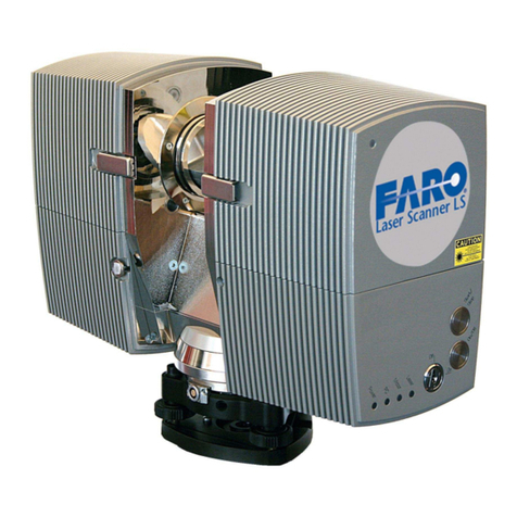
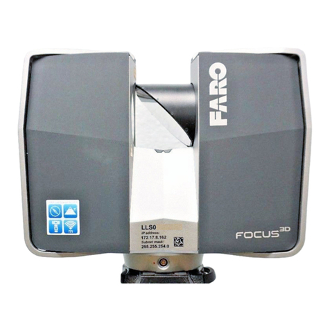
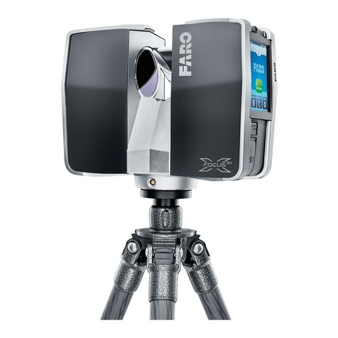
Faro Photon 20/80 User manual

Revised: April 10, 2008
© 2008 FARO Scanner Production GmbH
FARO Photon Laser
Scanner
20 / 80
User’s Manual

En
FARO Photon Laser Scanner – User’s Manual 2/68
Revised: April 10, 2008
© 2008 FARO Scanner Production GmbH
Copyright © 2008 FARO Technologies Inc. All rights reserved.
No part of this publication may be reproduced, or transmitted in any form or by any
means without written permission of FARO Technologies Inc.
FARO TECHNOLOGIES INC. MAKES NO WARRANTY, EITHER EXPRESS OR
IMPLIED, INCLUDING BUT NOT LIMITED TO ANY IMPLIED WARRANTIES OF
MERCHANTABILITY OR FITNESS FOR A PARTICULAR PURPOSE, REGARDING
FARO PHOTON LASER SCANNER AND ITS MATERIALS, AND MAKES SUCH
MATERIALS AVAILABLE SOLELY ON AN “AS-IS” BASIS. IN NO EVENT SHALL
FARO TECHNOLOGIES INC. BE LIABLE TO ANYONE FOR SPECIAL, COLLATERAL,
INCIDENTAL, OR CONSEQUENTIAL DAMAGES IN CONNECTION WITH OR
ARISING OUT OF THE PURCHASE OR USE OF FARO PHOTON LASER SCANNER
OR ITS MATERIALS. THE SOLE AND EXCLUSIVE LIABILITY TO FARO
TECHNOLOGIES INC., REGARDLESS OF THE FORM OF ACTION, SHALL NOT
EXCEED THE PURCHASE PRICE OF THE MATERIALS DESCRIBED HEREIN.
The information contained in this manual is subject to change without notice and does
not represent a commitment on the part of FARO Technologies Inc.
FARO Technologies Inc. Internal Control File Location:
X:\CONTROL\RECORDS\05MANUFA\PARTSPEC\5 Scanner LS\E600 FARO Photon Laser Scanner Manual EN.pdf

En
FARO Photon Laser Scanner – User’s Manual 3/68
Revised: April 10, 2008
© 2008 FARO Scanner Production GmbH
Table of contents
1Introduction 5
2Safety Precautions 6
2.1 General Safety Information 6
2.2 Electrical Safety 7
2.3 Laser Safety 7
2.4 Mechanical Security 9
3Equipment 10
4Your first scan - step-by-step 11
4.1 Setup of the FARO Photon Laser Scanner 11
4.1.1 Step 1 - Setting up the tripod 11
4.1.2 Step 2 – Tribrach preparation 12
4.1.3 Step 3 – Fixing the FARO Photon Laser Scanner 12
4.1.4 Step 4 – Connecting the FARO Photon Laser Scanner 13
4.1.5 Step 5 - Switching on the scanner 14
4.2 Installing and using the software 15
4.2.1 Step 6 – Software installation 15
4.2.2 Step 7 – Establishing an Ethernet connection to the scanner 15
4.3 Starting a scan 16
4.3.1 Step 8 – Unlocking the laser 16
4.3.2 Step 9 – Scanning 17
4.3.3 Step 10 – Shutting down the scanner 17
5Shutdown of the FARO Photon Laser Scanner 18
6The Software FARO Record 20
6.1 Installation 20
6.2 License 20
6.3 The scan bar 21
6.3.1 Scanner Parameter 21
6.3.2 Scanner Settings 29
6.3.3 Scanner selection 30
6.4 The Scanner menu 31
6.5 Status bar 31
7Color Option 32
7.1 Initial Setup of the camera 32
7.2 Setup before scanning 32
7.3 Scanning with color 37
7.4 Applying the pictures to the scan 41
7.4.1 Compensating horizontal shift 41
8Using FARO Record Mobile with a PDA 43

En
FARO Photon Laser Scanner – User’s Manual 4/68
Revised: April 10, 2008
© 2008 FARO Scanner Production GmbH
8.1 Setting up the WLAN connection 43
8.1.1 FARO Photon Laser Scanner 43
8.1.2 Setting up the WLAN of the PDA 46
8.2 Setting up Opera 50
8.3 Connecting to the Scanner 51
8.4 FARO Record Mobile Pages Description 52
8.4.1 Scan Page 52
8.4.2 Settings Page 53
8.4.3 Color Page 53
8.4.4 Project Page 54
8.4.5 Operator Page 54
8.4.6 Storage Page 55
8.4.7 Scans Page 55
8.5 Viewing scans 56
8.6 Auxiliary Files in the Scans Network Drive 57
9Cleaning Instructions for optics 58
9.1 Slightly contaminated mirror 59
9.2 Greatly contaminated mirror 60
9.3 Cleaning the receiver lens 60
9.4 Suppliers 60
10 Appendix 61
10.1 FARO Photon Laser Scanner error messages 61
10.2 FARO Photon Laser Scanner data and power cable 61
10.3 Helical scan mode (option) 62
10.3.1 Introduction 62
10.3.2 Operation 62
10.3.3 Electrical interface 65
10.3.4 Test device 66
11 Product Environmental Information 68

En
FARO Photon Laser Scanner – User’s Manual 5/68
Revised: April 10, 2008
© 2008 FARO Scanner Production GmbH
1 Introduction
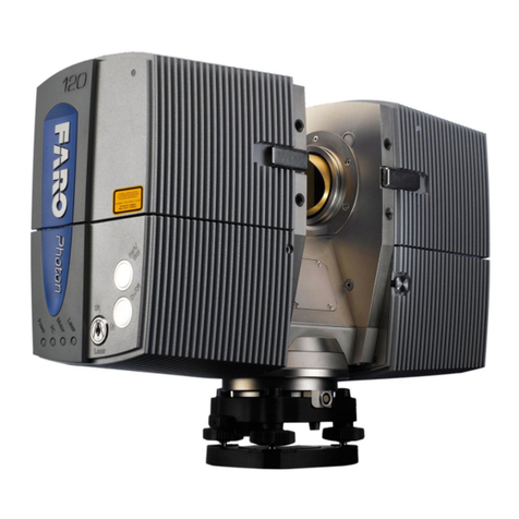
Fig.1 FARO Photon Laser Scanner
The FARO Photon Laser Scanner is a precise measuring instrument producing
photorealistic three dimensional images. The main features are
•high accuracy
•high resolution
•high speed
•modularity
•mobility
A list of possible applications can be found on the FARO webpage Uhttp://www.faro.comU.
This manual provides an introduction to the FARO Photon Laser Scanner.
As a minimum requirement, read at least the safety information and the step-by-step
guide before using the scanner!
Faro Scanner Production GmbH
Lingwiesenstraße 11/2
D-70825 Korntal-Münchingen
Tel.: +49 (0)7150 9797400
Fax: +49 (0)7150 97979400
Web: Uwww.faro.comU

En
FARO Photon Laser Scanner – User’s Manual 6/68
Revised: April 10, 2008
© 2008 FARO Scanner Production GmbH
2 Safety Precautions
2.1 General Safety Information
WARNING:
Do not expose this appliance to rain or moisture. For outdoor use, please ensure
that the device is protected against rain or spray water. Do not use the product near
water. Humidity must not be higher than 80%. Liquid entering the product’s enclosure
can lead to severe damage, fire or electric shocks.
When the product is transferred from a cold to a warm environment, water may
condense on some elements inside the product. Wait till the condensation water is
dried by itself before switching on the FARO Photon Laser Scanner.
Do not open the housing. You can damage the product by opening the housing and
the product’s warranty may be affected.
Read this User’s Manual carefully and retain it. Adhere to all warnings and follow the
instructions step by step.
Do not use parts which have not been supplied or recommended by FARO.
Servicing and repair must only be done by qualified service personnel authorized by
FARO.
Unplug this product from the power outlet and refer servicing to qualified service
personnel under the following conditions:
oThe power-supply cord or plug is damaged.
oThe product has been exposed to rain or water or other liquids.
oThe product has been dropped or damaged in any way.
oObjects have fallen into the product
oThe product does not operate normally by following the operating
instructions.
oThe product exhibits a distinct change in performance.
oWhen the required service and calibration date is due
Only replacement parts authorized by FARO may be used according to the
instructions obtained from FARO.
Do not expose the product to extreme temperatures. The ambient temperature must
not be lower or higher than given in the specifications. Do not use the FARO Photon
Laser Scanner near heat sources such as radiators, heat registers or other products
(including amplifiers) that produce heat.
Do not use the FARO Photon Laser Scanner in vicinity of strong magnetic or electrical
fields.
En
FARO Photon Laser Scanner – User’s Manual 7/68
Revised: April 10, 2008
© 2008 FARO Scanner Production GmbH
2.2 Electrical Safety
Do not open the housing. Dangerous high voltages are present inside the enclosure.
Only qualified service personnel should open the cabinet. Never push objects of any
kind into this product through openings as they may touch dangerous voltage points or
short-out parts. This could result in a fire or electric shock and damage the product.
This product should be operated only from the power source supplied or
recommended by FARO. Please ensure that the specifications of the AC converter are
met by your line voltage. If you do not know the power line voltage in your area, please
ask your local power company.
•This product may be equipped with a three-wire grounding-type plug, a plug
having a third (grounding) pin. This plug will only fit into a grounding-type power
outlet. This is a safety feature. If you are unable to insert the plug into the outlet,
contact your electrician to replace your outlet (and not the plug).
2.3 Laser Safety
CAUTION: This product employs a laser system. To prevent direct exposure to the
laser beam, do not try to open the enclosure.
The FARO Photon Laser Scanner should only be operated by trained personnel.
The outlet of the laser beam is marked by stickers. If the laser is armed,
do not look into the direction of the laser without wearing laser safety
glasses. Viewing the laser beam without protection from a short distance
may pose an eye hazard. Do no stare into the beam or view directly with
optical instruments. Do not place mirrors or objects with reflective
surface into the beam.
Fig.2 Warning label

En
FARO Photon Laser Scanner – User’s Manual 8/68
Revised: April 10, 2008
© 2008 FARO Scanner Production GmbH
Fig.3 Safety sticker on scanner
Fig.4 Safety Sticker
When operating the FARO Photon Laser Scanner, you must adhere to the eye safety
distance (nominal ocular hazard distance NOHD). The eye safety distance is
dependent on the requested resolution (see chapter 6.3.1.1.) and on the laser power.
Personnel working in distances shorter than the eye safety distance must wear laser
safety glasses. Prevent people without laser safety glasses from entering this area (e.g.
by using a safety fence).
Regarding eye safety, laser radiation from the FARO Photon Laser Scanner can be
regarded as coming from a pulsed laser source, with repetition rate decreasing and
pulse duration increasing with the requested resolution. By this, the eye safety distance
becomes dependent on the requested resolution. Repetition rate and pulse duration for
different scanning resolutions are as follows:

En
FARO Photon Laser Scanner – User’s Manual 9/68
Revised: April 10, 2008
© 2008 FARO Scanner Production GmbH
Resolution Repetition rate [Hz] Pulse duration [s]
1/1 3 0,00760
1/2 6 0,00380
1/4 12 0,00190
1/5 15 0,00152
1/8 24 0,00095
1/10 30 0,00076
1/16 48 0,00048
Tab. 1 Repetition rate and pulse duration
2.4 Mechanical Security
•The FARO Photon Laser Scanner may only be used when set on a flat and
stable surface. People can be hit and severe injuries can be caused by an
overturn of the FARO Photon Laser Scanner. Only use equipment recommended
by FARO and follow the setup instructions of the manufacturer.
•If using a cart, move the setup with special care. Never move the cart by pulling
at the data or power cables. Pushing or pulling of the cart with too much force,
sudden stops or an uneven surface can cause an upset of the scanner.
•The scanner is rotating clockwise up to 360 degrees when performing a scan.
Ensure that the case of the scanner can rotate freely and does not hit any objects
during the scan.
•While scanning and for a short period after the scan, the mirror unit is rotating
with high speed. Do not touch the rotating mirror unit with your hands or any
objects. You could hurt yourself and cause damage to the scanner.

En
FARO Photon Laser Scanner – User’s Manual 10/68
Revised: April 10, 2008
© 2008 FARO Scanner Production GmbH
3 Equipment
Fig.5 Equipment
Check that all of the equipment that is required for the operation of this product is
available, as listed below.
•Scanner carry case
•FARO Photon Laser Scanner 20 / 80
•Laser lock key
•Scanner data and power cable
•Scanner connector box
•Power supply unit with cable
•Ethernet cable
•Tribrach
•CD with FARO Record software
•User’s manual
•Battery pack (optional)
•Tripod (optional)
Retain all packing material as you may require them at a later stage.

En
FARO Photon Laser Scanner – User’s Manual 11/68
Revised: April 10, 2008
© 2008 FARO Scanner Production GmbH
4 Your first scan - step-by-step
This chapter will guide you step-by-step from setting up the scanner to doing the first
scan using FARO Record.
4.1 Setup of the FARO Photon Laser Scanner
4.1.1 Step 1 - Setting up the tripod
Extend and lock all legs of the tripod. Check that the tripod adjustment arrangements
have been locked and that the legs are of even length. Ensure that the surface is stable,
that the tripod feet are secured and that the tripod is firm in its position.
Fig.6 Aluminum tripod
Fig.7 Carbon fiber tripod

En
FARO Photon Laser Scanner – User’s Manual 12/68
Revised: April 10, 2008
© 2008 FARO Scanner Production GmbH
4.1.2 Step 2 – Tribrach preparation
4.1.2.1 Using the aluminum tripod
Open the locking screw of the tripod head and remove it from the tripod. Screw the
tripod head to the base of the tribrach. Make sure that it is firmly tightened.
Fig.8 Attaching the tripod head
4.1.2.2 Using the carbon fiber tripod
Open the fastener of the tribrach as shown in the picture below and remove the tribrach
from the base of the scanner.
Fig.9 Removing the tribrach from the scanner
Screw the tribrach on the carbon fiber tripod.
Fig.10 Tribrach on the tripod
4.1.3 Step 3 – Fixing the FARO Photon Laser Scanner
Remove scanner from case, check outer casing for any signs of damage or distortion.
Check mirror for damage due to scratches, cracks, distortion and inspect for
cleanliness.

En
FARO Photon Laser Scanner – User’s Manual 13/68
Revised: April 10, 2008
© 2008 FARO Scanner Production GmbH
4.1.3.1 Using the aluminum tripod
Place the scanner on the tripod. Once in position lock the scanner into place by using
the tripod’s head locking screw. Test that the scanner is correctly locked in place by
gently attempting to lift it from the tripod.
4.1.3.2 Using the carbon fiber tripod
Place the scanner on the tribrach and lock the fastener of the tribrach. Test that the
scanner is correctly locked in place by gently attempting to lift it from the tripod.
4.1.4 Step 4 – Connecting the FARO Photon Laser Scanner
Fig.11 Connection scheme
•Insert the 90° bend connector of the blue data and power cable into the scanner.
Fig.12 Insert 90° bend connector into scanner
•Attach the blue data and power cable to one of the legs of the tripod.
Connector
box
Power
supply
Data and power cable
or
Ethernet cable
Battery
pack

En
FARO Photon Laser Scanner – User’s Manual 14/68
Revised: April 10, 2008
© 2008 FARO Scanner Production GmbH
Fig.13 Blue data and power cable at tripod leg
Without battery
•Ensure that the connector box is switched off (red button pressed).
•Insert the bigger connector of the blue data and power cable into the connector
box.
•Insert Ethernet cable into PC port as specified by PC manufacturer and into the
connector box. If the Ethernet connection does not work, an Ethernet switch and
two ordinary Ethernet cables might have to be put between PC and connector
box.
•Check that the power supply unit is switched off and unplugged. Connect power
supply cable to the connector box; connect power cable into an approved power
supply source.
With battery
•Ensure that the Battery is switched off.
•Insert the connector of the blue data and power cable into the battery.
•Insert Ethernet cable into PC port as specified by PC manufacturer and into the
battery. If the Ethernet connection does not work, an Ethernet switch and two
ordinary Ethernet cables might have to be put between PC and battery.
4.1.5 Step 5 - Switching on the scanner
•Check that the laser lock is in Off position.
•Switch on the external operating PC and when the PC is ready, switch on
the power for the scanner by turning the red button on the connector box
or, if you have a battery pack, by using the switch on the battery pack.
The scanner’s Power LED will be on.
•Start the scanner by pushing the On/Off button. This will start the boot
procedure of the internal PC, which will be indicated by the PC LED
turning to red for a moment and then flashing in green.

En
FARO Photon Laser Scanner – User’s Manual 15/68
Revised: April 10, 2008
© 2008 FARO Scanner Production GmbH
•When the PC is ready, the PC LED will remain green, while the
Motor LED will be flashing in green till the initial parameter transfer
is finished.
•When the base unit and the mirror unit are ready, the Motor LED will stop
flashing and remain green.
4.2 Installing and using the software
4.2.1 Step 6 – Software installation
If FARO Record is not already installed on your PC, insert the CD supplied with the
scanner and follow the installation instructions on the screen.
4.2.2 Step 7 – Establishing an Ethernet connection to the scanner
Run FARO Record and click on the symbol to select your scanner by a left-click on
the scanner’s name. Open the context menu with a right-click to connect to the scanner.
The status icon will change to “Connected” after the connection has been established
and the “start scan”-symbol ( ) will become activated ( ).
Fig.14 FARO Record – scanner selection
4.2.2.1 Connection problems
A connection can only established if the scanner and the operating PC have compatible
IP addresses and compatible subnet masks. If they don't, this is indicated by the Net
incompatibility icon . You can check the parameters on the operating PC using the
command ipconfig in the windows command prompt.
Fig.15 Checking IP address with ipconfig
If the operating PC has no valid IP address (like in Fig.15) you might have to assign a
static IP address to the PC. If the operating PC is part of a LAN, ask your system
administration to do this. Else you can configure the operating PC's IP address in
Windows' Control Panel →Network Connections →Local Network Connection (LAN)

En
FARO Photon Laser Scanner – User’s Manual 16/68
Revised: April 10, 2008
© 2008 FARO Scanner Production GmbH
→Properties →Internet Protocol (TCP/IP) →Properties, using the option "Use the
following IP address" and providing a valid IP address and subnet mask.
Fig.16 TCP/IP Properties
If the scanner selection dialog shows a net incompatibility you have to change the IP
address of the scanner remotely. Select the command Set IP address form the
scanner's context menu as shown in Fig.17.
Fig.17 Net incompatibility problems
Change the IP address of the scanner to an address that only differs from the operating
PC's IP address by the last number. The subnet mask of PC and scanner should be
identical. If you sometimes have the scanner connected to your LAN, ask your system
administrator for a yet unused IP address.
Fig.18 Changing the Scanner's IP address
4.3 Starting a scan
4.3.1 Step 8 – Unlocking the laser
•Insert the key into the lock and turn it to the On position.
•The Laser LED will flash green while exchanging parameters with the PC
unit.

En
FARO Photon Laser Scanner – User’s Manual 17/68
Revised: April 10, 2008
© 2008 FARO Scanner Production GmbH
•A red light on the upper part of the scanner and the green Laser LED will
indicate that the laser is unlocked and ready for scanning.
If you are in a distance less than the eye safety distance, wear your
laser safety glasses now and take care that there are no people in
the potentially dangerous area unless they are wearing laser safety
glasses.
Remember that the scanner is turning and the mirror unit is rotating with a high speed.
Ensure that the scanner can move freely and that no objects can touch the mirror unit.
4.3.2 Step 9 – Scanning
You can start your first scan either by clicking on the symbol (Start Scan) in FARO
Record, or by pressing the Start button on the scanner. The software might ask for a
name and a place for saving the scan. After this, the scan starts and a progress bar will
be displayed.
In the very first scan after the scanner has been switched on, the scanner starts turning
counterclockwise for a brief moment. Then it stops and starts scanning in clockwise
motion. All consecutive scans are then taken without the initial counterclockwise motion.
On completion of the scan the scanner rotates counterclockwise back into its initial
position.
The result of the scan will be displayed on the screen.
4.3.3 Step 10 – Shutting down the scanner
Lock the laser by turning the key to the Off position. Use the On/Off button on the
scanner (pressing it for at least 5 seconds) or the FARO Record Software to shut down
the scanner.
The PC LED will be flashing green during the shutdown and the
Laser and the Motor LED will be switched off.
After the shutdown is finished, the PC LED will be off and you can
switch off the power supply of the scanner.

En
FARO Photon Laser Scanner – User’s Manual 18/68
Revised: April 10, 2008
© 2008 FARO Scanner Production GmbH
5 Shutdown of the FARO Photon Laser Scanner
The FARO Photon Laser Scanner has a PC with a hard drive integrated. This internal
PC must be shut down before turning off the power supply. If the power supply is
disconnected or switched off without the scanner being previously shut down, it may
damage the internal PC and might lead to a loss of data.
To shut down the FARO Photon Laser Scanner, select “Shutdown Scanner” in the
Scanner menu of the FARO Record software. While the scanner is shutting down a
dialog will appear showing the shut down status. DO NOT turn off the power of the
scanner until this dialog has disappeared and the shut down cycle is complete.
Fig.19 FARO Record – shutdown message
Alternatively you can use the button on the scanner to shut
down the scanner. Press the On/Off button on the scanner
for at least 5 seconds. Wait until the shutdown cycle is
complete and the green Motor and PC LEDs are switched
off.
Once the scanner has been completely shut down, the external PC may be shut down
and all power then turned off. When switching off the power, the scanner’s Power LED
will change to red for a short moment and will then be switched off. Disconnect all
cables and secure the equipment in protective cases.
Take care to unplug the bend connector from the scanner by pulling at the
connector only! Do not pull at the combined data and power cable. Else the
connector and the internal PC of the scanner can be damaged!
Fig.20 Unplugging the bend connector

En
FARO Photon Laser Scanner – User’s Manual 19/68
Revised: April 10, 2008
© 2008 FARO Scanner Production GmbH
Please note: If the scanner had not been shut down properly (e.g. after having applied
the emergency stop), the next boot of the scanner could take more time as usual as the
scanner will check its hard disk for errors.

En
FARO Photon Laser Scanner – User’s Manual 20/68
Revised: April 10, 2008
© 2008 FARO Scanner Production GmbH
6 The Software FARO Record
Using FARO Record you can connect to the FARO Photon Laser Scanner, configure
parameters, start scans, and view the results of your scans and shutdown the scanner.
Fig.21 FARO Record
In this manual only the features which are directly linked to performing a scan will be
addressed. Please refer to the FARO Record user’s manual for the many other features
of the software (like viewing or measuring objects).
6.1 Installation
Insert the Installation CD supplied with the scanner, select the product and follow the
installation instructions on the screen. An installation wizard will guide you during
installation. You must belong to the group of administrators or power users to install the
software.
6.2 License
After the trial period, you need a license to use FARO
Record. If you change your hardware or if you want
to use FARO Record on a different computer, you
will also need a new license, as the license is bound
to a system ID.
With the license manager (Help→License Manager)
you can view your licenses, send an e-mail to FARO
requesting a license (Send) and add the licenses that
you have received from FARO (Add). After adding a
license, press OK or Apply.
Fig.22 License Manager
Scan bar
Scan view
Status bar
Scanner menu
Table of contents
Other Faro Scanner manuals

Faro
Faro Focus 3D X 130 Installation guide

Faro
Faro GEO SLAM ZEB Horizon User manual

Faro
Faro Freestyle 3D User manual

Faro
Faro FocusM 70 User manual

Faro
Faro ZEB Revo RT User manual

Faro
Faro ScanPlan User manual

Faro
Faro Focus3D 20 User manual

Faro
Faro Edge FaroArm User manual

Faro
Faro FOCUS3D X 130 User manual

Faro
Faro ScanPlan User manual
Popular Scanner manuals by other brands

Fujitsu
Fujitsu S510 - ScanSnap - Document Scanner Brochure & specs

Kodak
Kodak 5500 - EASYSHARE All-in-One Color Inkjet User reference

Revopoint
Revopoint INSPIRE quick start guide

Canon
Canon ScanFront 330 Brochure & specs

Panasonic
Panasonic KV-S6040W - Document Scanner operating instructions

Hesai
Hesai PandarXT-32 user manual