manuals.online logo
Brands
  1. Home
  2. •
  3. Brands
  4. •
  5. Festo
  6. •
  7. Accessories
  8. •
  9. Festo SDE5 series User manual

Festo SDE5 series User manual

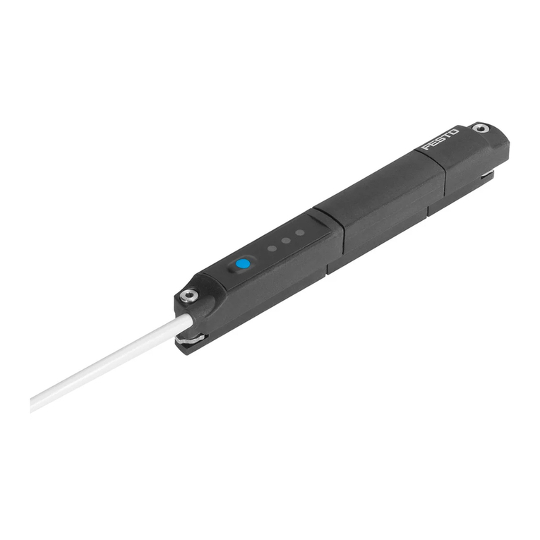
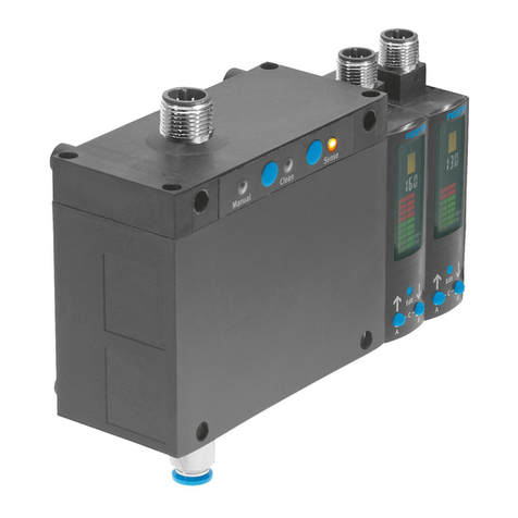
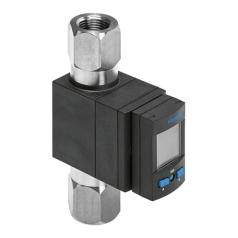
Pressure sensor SDE5
Festo AG & Co. KG
Ruiter Straße 82
73734 Esslingen
Germany
+49 711 347-0
www.festo.com
Operating instructions
Original instructions
8078140
2017-09e
[8068031]
For all available product documentation èwww.festo.com/pk
1 Product description
1.1 Overview
SDE5 installed on the MS series
service unit
3
2
1
4
1
2
3
5
1Electrical connection
2LED indicator (continuous
transmission of the LED indicator
through fibre-optic cable)
3Edit button (not on SDE5-…X)
4Connection 2 for compressed air
or vacuum
5Connection 1 for compressed air
or vacuum
Fig. 1
1.2 Characteristics
Key feature Order code Specification
Type SDE5 Pressure sensor
Pressure
measuring
range
-V1/-B2/-D2/
-D6/-D10
èChapter 10 Technical data.
Supply port Relative pressure
-Z Differential pressure
Output
function1)
-FP Freely programmable
-O
-C
Normally open contact (NO), fixed hysteresis, mode 0
Normally closed contact (NC), fixed hysteresis, mode 0
-O1
-C1
Normally open contact (NO), fixed hysteresis, mode 1
Normally closed contact (NC), fixed hysteresis, mode 1
-O2
-C2
Normally open contact (NO), teachable hysteresis, mode 2
Normally closed contact (NC), teachable hysteresis, mode 2
-O3
-C3
Normally open contact (NO), fixed hysteresis, mode 3
Normally closed contact (NC), fixed hysteresis, mode 3
-NF Analogue output 0 … 10 V
Pneumatic
connection
-Q4/-Q6/
-T532/-T14
At both ends for standard O.D. tubing
-N-4 mm/-N-6 mm/-N-Â/-N-¼
-Q4E/-Q6E/
-T532E/-T14E
At one end for standard O.D. tubing
-N-4 mm/-N-6 mm/-N-Â/-N-¼
Electrical
output
-P/-N Switching output PNP/NPN
-V Pressure proportional voltage 0 ... 10 V
Electrical
connection
-K Cable, 2.5 metres long, 3-core
-M8 Plug connector M8x1, 3-pin
Teach point -X
-Y
X teach point permanently set
Y teach point permanently set
1) Signal curves, switching functions and operating modes èFig. 14 and Fig. 15
Fig. 2
2 Function and application
The pressure sensor SDE5 is intended for the proper monitoring of the pressure
inthe compressed air system. The SDE5 converts pneumatic pressure values into
apressure proportional voltage. Depending on the design of the pressure sensor,
this signal is converted into a digital switching signal (SDE5-…-P-…/SDE5-…-N-…)
or it is amplified for an analogue output (SDE5-…-NF-…-V).
The monitored pressure values record either the relative pressure or the
differential pressure (SDE5-…-Z-…).
The pressure sensor with switching output closes or opens a circuit when the
switching pressure is reached. The switching element function is preset at the
plant and can only be modified with the SDE5-…-FP-…. The SDE5 is available with
different switch/teach functions (èFig. 2).
MS series service unit with pressure sensor SDE5
The pressure sensor SDE5 on the series MS service unit is already permanently
attached and pneumatically connected on delivery. Fig. 3 shows the allocation
between the MS service unit and the attached pressure sensor.
MS series service unit Attached pressure sensor
MS4/6-…-AD7 SDE5-D10-O-…-P-M8
MS4/6-…-AD8 SDE5-D10-C-…-P-M8
MS4/6-…-AD9 SDE5-D10-O3-…-P-M8
MS4/6-…-AD10 SDE5-D10-C3-…-P-M8
Fig. 3
3 Requirements for product use
 Use the product in its original status, without any unauthorised product
modifications.
 Observe the specified limits (e.g. operating medium, pressures, forces,
temperatures).
 Take into consideration the ambient conditions at the location of use.
 Observe the regulations which apply in your location (e.g. from trade
associations or from national institutions).
 Remove everything used for protection during transport such as protective wax,
films, caps and cardboard boxes. The material used in the packaging has been
specifically chosen for its recyclability (exception: oil-impregnated paper =
residual waste).
 The device is intended for use in an industrial environment. Measures may need
to be implemented in residential areas for interference suppression.
 Remove dirt particles in the supply lines by blowing out the pipes and hoses.
This protects the device from premature failure or heavy wear.
Range of applications and certifications
The information in this section, in combination with the UL marking on the product,
must be observed in order for there to be compliance with the certification
conditions of Underwriters Laboratories Inc. (UL) for USA and Canada. Observe the
following English-language remarks from UL:
This device is intended to be used with a Class 2 power source or Class 2
transformer in accordance with UL1310 or UL1585.
As an alternative a LV/C (Limited Voltage/Current) power source with one of the
following properties can be used:
– This device shall be used with a suitable isolating source such that the
maximum open circuit voltage potential available to the product is not more
than 30 V DC and the current is limited to a value not exceeding 8 amperes
measured after 1 minute of operation.
– This device shall be used with a suitable isolating source in conjunction with
afuse in accordance with UL248. The fuse shall be rated max. 3.3 A and be
installed in the 30 V DC power supply to the device in order to limit the available
current.
Note that, when more than one power supply or isolating device is used,
connection in parallel is not permitted.
In determining the acceptability of the combination, the following details are to be
examined:
– The suitability of the final mounting is to be determined.
– The devices are to be mounted in an enclosure with adequate strength and
thickness.
– The devices have not been examined for field wiring. The suitability of the final
application is to be determined.
UL approval information
Product category code NRNT2 (USA) or
NRNT8 (Canada)
File number E253738
Considered standards UL 508, 17th edition,
C22.2 No. 14-95
UL mark
Fig. 4
4 Installation
Note
The pressure sensor SDE5 on the series MS service unit is already permanently
attached and pneumatically connected when delivered.
4.1 Mechanical system
 If several wall holders are used: push
the dovetail of wall holder 1into the
connecting slot of the next wall holder
(press out lug 2). 1
2
Fig. 5
 Mount the first and the last wall holder
with 2 screws each (4 mm) at the
designated positions.
 If more than 3 wall holders are being
used: also mount every second wall
holder with 2 screws each (4 mm).
Fig. 6
 Press the SDE5 into the wall holders.
Iffitted correctly, all four spring clips 3
will latch audibly into place.
The lug of wall holder 4can be broken
off in case of individual mounting. This
gives an extended view of the all-round
LED (èFig. 1).
3
4
Fig. 7
4.2 Pneumatic system
Push-in connector at one end
 Connect the tubing to pneumatic
connection 1.
P1
Fig. 8
Push-in connector at both ends
 Check the pressure ratios.
With the pressure sensor for differential
pressure (SDE5-…-Z-…), the higher
pressure must be present at connection 1.
The following is valid:
Differential pressure = p1 - p2.
 Connect tubing to pneumatic
connections 1and 2.
P
P
1
2
Fig. 9
4.3 Electrical system
Warning
Only use power sources which guarantee reliable electrical isolation of the
operating voltage according to IEC/DIN EN 60204-1. Also observe the general
requirements for PELV power circuits according to IEC/EN 60204-1.
Note
Long signal lines reduce the immunity to interference.
 Make sure that the length of the signal line is always shorter than 30 metres.
The tightening torque for the cap nut at the plug connector is max. 0.3 Nm.
Pin allocation and circuit diagrams
Pin Allocation Core colours1) Plug connector
1Operating voltage +24 V DC Brown (BN)
2/4 Switching output A (Out A) or analogue
output
Black (BK)
30 V Blue (BU)
1) When using the connecting cable from the electrical accessories
Fig. 10
Circuit diagrams
SDE5-…-P-…-K
Switching output cable connection
SDE5-…-P-…-M8
Switching output plug connection
SDE5-…-N-…-K
Switching output cable connection
SDE5-…-N-…-M8
Switching output plug connection
SDE5-…-V-…-K
Analogue output cable connection
SDE5-…-V-…-M8
Analogue output plug connection
Fig. 11
5 Commissioning
Fig. 12 shows an overview of the possible settings and displays. The activities are
described in the subsequent sections.
RUN mode
(A)
(C)
(B)
Mode 3 Mode 2 Mode 1
Ensure there is a power supply for at least 10 s.
(A) Mode display Display of the set mode (only with …-FP)
(B) Mode selection Selection of modes 1 to 3 (only with …-FP)
(C) Switching pressure
setting
Teaching the switching pressures TP1 and TP2
(mode 0…3)
Fig. 12
Caution
After teaching, the values are written to the internal memory. If the saving
process is unexpectedly aborted (e.g. from a power interruption), the transfer
process to the memory can not be completely carried out and the device
becomes unusable.
 Ensure that there is power supply to the device for at least 10 seconds after
teaching.
Note
Unintended pressing of the Edit button can cause an accidental alteration of
thepreset switching pressure (e.g. setting the SDE5 to a switching pressure of
0 bar/0 MPa when the operating pressure is missing).
Definitions:
– Pressure p: relative pressure or differential pressure (also vacuum with
SDE5-V1/B2).
– Switching pressure SP: pressure p at which the SDE5 switches.
– Teach pressure TP1, TP2: pressure p at time of programming.
5.1 SDE5-…X without Edit button
The SDE5-…X without Edit button is preset at the factory with fixed switching
pressures. The SDE5-…X does not require further setting for commissioning.
5.2 SDE5-…-NF-…-V with analogue output
1. Switch on the operating voltage.
èThe LED illuminates green.
2. Pressurise the SDE5 with the desired pressure p.
èThe pressure measurement value at the analogue output is an electrical
pressure-proportional signal in the range 0…10 V depending on the pres
sure measuring range (èFig. 13).
Signal range of analogue
output
0 V …5 V …10 V
bar MPa bar MPa bar MPa
Pressure measuring
range [bar, MPa]
SDE5-V1 0 0 … –0.5 –0.05 … –1 –0.1
SDE5-B2 –1 –0.1 … 0 0 … 1 0.1
SDE5-D2 0 0 … 1 0.1 … 2 0.2
SDE5-D6 0 0 … 3 0.3 … 6 0.6
SDE5-D10 0 0 … 5 0.5 … 10 1
Fig. 13
5.3 SDE5-…-O/C-…-P/N with switching output
Set the switching pressure SP with one teach pressure TP1
1. Switch on the operating voltage.
2. Pressurise the SDE5 with the desired teach pressure TP1.
3. Press the Edit button (2 s) until the LED flashes.
4. Let go of the Edit button.
èThe current teach pressure TP1 is saved as the switching pressure SP.
5. Ensure that there is power supply for at least 10 seconds.
6. Carry out a test run with various pressures to ascertain whether the SDE5
switches as desired. When the switching signal is emitted, the LED also
illuminates.
Signal curve over the applied pressure p with switching points
Mode NO contact NC contact
Mode 0:
Threshold value
comparator
(threshold value
with fixed
hysteresis)
SDE5-…-O SDE5-…-C
TP1 = teach pressure, SP = switching pressure, Hy = hysteresis, A = switching output (Out A)
Fig. 14
Note
The switching output behaviour of the SDE5-B2 and of the SDE5-V1 differ from
each other in the vacuum range 0…–1 bar/0…–0.1 MPa1).
1) Example for switching point at –0.5 bar/–0.05 MPa, inlet pressure = 0 bar/0 MPa:
switching status SDE5V1O…: output open, switching status SDE5-B2-O-…: output closed.
5.4 SDE5-…-O1/O2/O3/C1/C2/C3-…-P/N with switching output
Set the switching pressure SP with two teach pressures TP1/TP2
1. Switch on the operating voltage.
2. Pressurise the SDE5 with one teach pressure, e.g. for TP1 (you could also start
with TP2, since the functions of the normally closed contact and/or normally
open contact are specified).
3. Press the Edit button (2 s) until the LED flashes.
4. Release the Edit button.
èThe current teach pressure TP1 is saved.
èThe LED flashes.
5. Pressurise the SDE5 with the other teach pressure, e.g. TP2.
6. Press the Edit button until the LED stops flashing.
7. Release the Edit button.
èThe current teach pressure TP2 is saved.
8. Ensure that there is power supply for at least 10 seconds.
9. Carry out a test run with various pressures to ascertain whether the SDE5
switches as desired. When the switching signal is emitted, the LED also
illuminates.
Signal curve over the applied pressure p with switching points
Mode NO (normally open contact) NC (normally closed contact)
Mode 1:
Threshold value
comparator
(threshold value
with fixed
hysteresis),
switching pressure
SP = 1/2 (TP1 + TP2)
Preset mode for
output function FP
SDE5-…-O1 SDE5-…-C1
Mode 2:
Hysteresis
comparator
(threshold value
with variable
hysteresis)
SDE5-…-O2 SDE5-…-C2
Mode 3:
Window comparator
with fixed hysteresis
SDE5-…-O3 SDE5-…-C3
TP1 = teach pressure, SP = switching pressure, Hy = hysteresis, A = switching output (Out A)
Presettings: TP1 = 20% FS; TP2 = 80% FS TP1 = 80% FS; TP2 = 20% FS
Fig. 15
5.5 SDE5-…-FP-…-P/N with switching output
Mode display
The LEDs indicate the current mode by flashing (e.g. 3 x flashes for mode 3).
Themode is displayed a total of 5 times in succession before the SDE5 returns to
RUN mode.
Mode 1 Mode 2 Mode 3
LED flashing
sequence for the
set mode 5x 5x 5x
LED flashing
sequence with
change of mode ...
Fig. 16
Set mode
1. Switch on the operating voltage.
2. First briefly press the Edit button 1 time (2 s) and then release it.
èThe LED indicates the mode currently set (èFig. 16).
3. While the mode is displayed, press the Edit button again until the desired mode
is displayed for the operation.
4. Release the Edit button.
èThe current mode is saved.
5. Ensure that there is power supply for at least 10 seconds.
Note
The switching pressure SP must be reset after the mode is selected or changed.
Set the switching pressure SP with two teach pressures TP1/TP2
Note
The sequence of the teach pressures for the switching pressure setting affects
the switching element function (normally closed contact/normally open contact)
of the SDE5.
 Take the following relationship into account:
TP1 TP2: Programming as NO contact
TP1 (TP2 + 2% full-scale): Programming as NC contact
1. Note down the teach pressures TP1 and TP2.
2. Pressurize the SDE5 with the first teach pressure TP1.
3. Press the Edit button (2 s) until the LED flashes.
4. Release the Edit button.
èThe current teach pressure TP1 is saved.
èThe LED flashes.
5. Pressurize the SDE5 with the second teach pressure TP2.
6. Press the Edit button until the LED stops flashing.
7. Release the Edit button.
èThe current teach pressure TP2 is saved.
8. Ensure that there is power supply for at least 10 seconds.
9. Carry out a test run with various pressures to ascertain whether the SDE5
switches as desired. When the switching signal is emitted, the LED also
illuminates.
Signal curve over the applied pressure p with switching points
The diagrams for NO (normally open contact, TP1 < TP2) and NC (normally closed
contact, TP1 (TP2 + 2% full-scale)) show the relationship between teach
pressure, switching pressure and hysteresis (èFig. 15).
6 Operation
Warning
Risk of injury from high temperatures.
Extreme pneumatic conditions (high cycle rate with large pressure amplitude)
can heat the device over 80°C.
 Select the operating conditions (in particular the ambient temperature,
pressure amplitude, cycle rate, current consumption) such that the device
does not heat up above the maximum permitted operating temperature.
 Observe the operating conditions.
 Switch on the operating voltage.
èThe device is working in RUN mode (basic status).
LED indicator Meaning
LED illuminates yellow SDE5-…-P/-N-…(switching output): pressure p >switching pressure
LED does not illuminate SDE5-…-P/-N-…(switching output): pressure p <switching pressure
LED flashes quickly Teach procedure (èFig. 12)
LED flashes slowly Only SDE5-…-FP: display and setting of the switching function
LED illuminates green Only SDE5-…-V (analogue output): ready status (RUN mode)
Fig. 17
7 Maintenance and care
Clean the SDE5 on the outside
1. Switch off the operating voltage.
2. Switch off the compressed air.
3. Clean the outside of the SDE5 with a soft cloth.
Permissible cleaning agents are soap suds (max. +50 °C) and all non-abrasive
agents.
8 Disassembly
1. Switch off the operating voltage.
2. Switch off the compressed air.
3. Disconnect the electrical and pneumatic connections from the SDE5.
4. Release the SDE5 from the wall holder.
Forthis, slide a screwdriver into the slot 1
and prise the SDE5 out of the wall holder.
1
Fig. 18
9 Fault clearance
Malfunction Possible cause Remedy
No LED indicator Pressure p < switching pressure SP Regular operating status (èFig. 17)
No power supply or no
permissible operating voltage
Switch on power supply/adhere to the
permitted operating voltage range
Connections mixed up
(reversepolarity)
Wire the SDE5 in accordance with the
pin allocation
Pressure failure Eliminate pressure failure
SDE5 defective Replace device
LED indicator or
switching output
does not react in
accordance with
the settings made
Short circuit or overload at the
output
Eliminate short circuit/overload
Incorrect switching point taught
(e.g. at 0 bar/0 MPa)
Repeat teach procedure
SDE5 defective Replace device
Fig. 19
10 Technical data
Type SDE5 -V1 -B2 -D2 -D6 -D10
General information
Certification RCM, c UL us – Recognized (OL)
CE marking (èDeclaration of conformity) In accordance with EU EMC Directive
Note on materials RoHS-compliant
Input signal/measuring element
Pressure measuring range1) [bar] 0…–1 –1…1 0…2 0…6 0…10
Pressure measuring range1) [MPa] 0…–0.1 –0.1…0.1 0…0.2 0…0.6 0…1
Max. overload pressure [bar] 5 5 6 15 15
Max. overload pressure [MPa] 0.5 0.5 0.6 1.5 1.5
Operating medium Compressed air in accordance with
ISO8573-1:2010[7:4:4], lubricated operation
possible
Temperature of medium [°C] 0…+50
Ambient temperature [°C] 0…+50
Output, general
Repetition accuracy [% FS] ±0.3 (short time)
Temperature coefficient [% FS/K] Max. ±0.05
Short circuit protection Yes
Overload protection Available
Switching output
Accuracy [% FS] Max. ±0.5
Switching time (on/off) [ms] 2 (typical)/4 (max.)2)
Max. output current [mA] 100
Capacitive load maximum DC [nF] 100
Voltage drop [V] Max. 1.8
Inductive protective circuit Adapted to MZ, MY, ME coils
Analogue output
Output characteristic curve1) [V] 0…10
Accuracy [% FS] ±3 (room temperature: 20…25°C)
[% FS] Max. ±4 (room temperature: 0…50°C)
Rise time [ms] 5 (typical) with resistive load
Min. load resistance [kΩ] 2
Electronics
Operating voltage range [V DC] 15…30
No-load supply current [mA] Max. 34
Ready-state delay [ms] 10
Reverse polarity protection For all electrical connections
Electromechanics
Max. cable length [m] 30
Information on materials – cable sheath PUR
Information on materials – plug connector
housing
Brass (nickel-plated, chrome-plated)
Cable diameter [mm] 2.9
Nominal conductor cross section [mm2] 0.14
Mechanical
Mounting position As desired, preferably vertical3)
Information on materials – housing/keypad Polyamide (POM) reinforced
Information on material – fibre-optic cable PA
Display/operation
Threshold value setting range:
– Switching pressure [% FS] 0…100 (recommended work range 1…99)
– Hysteresis (mode 2) [% FS] 0…100 (recommended work range 1…99)
– Hysteresis (mode 0, 1, 3) [% FS] 2 (permanently set)
Immission/emission
Storage temperature [°C] –20…+80
Degree of protection
(in accordance with EN 60529)
IP40
Protection class
(in accordance with DIN VDE 0106-1)
III
Shock resistance
(in accordance with EN 60068-2)
30 g acceleration with 11 ms duration (half-sine)
Vibration resistance
(in accordance with EN 60068-2)
0.35 mm travel, 5 g acceleration at 10 … 150 Hz
Corrosion resistance class CRC 2
1) Starting value…End value.
2) Switching times do not apply with additional function activated ...- TF (filter function).
3) No condensed water should be allowed to accumulate in the pressure measuring cell.

Other manuals for SDE5 series

5

Other Festo Accessories manuals

Festo SOPA Series User manual

Festo

Festo SOPA Series User manual

Festo SBSI-EN User manual

Festo

Festo SBSI-EN User manual

Festo SFAM-62 User manual

Festo

Festo SFAM-62 User manual

Festo SDE5 series User manual

Festo

Festo SDE5 series User manual

Festo SDAT-MHS User manual

Festo

Festo SDAT-MHS User manual

Festo SBSi User manual

Festo

Festo SBSi User manual

Festo SFAW Series User manual

Festo

Festo SFAW Series User manual

Festo SFAB-PNLK Series User manual

Festo

Festo SFAB-PNLK Series User manual

Festo SOPA User manual

Festo

Festo SOPA User manual

Festo SOOE-RS PNLK-T Series User manual

Festo

Festo SOOE-RS PNLK-T Series User manual

Festo SRBC Series User manual

Festo

Festo SRBC Series User manual

Festo SRAP-M-CA1 Series User manual

Festo

Festo SRAP-M-CA1 Series User manual

Festo SFAW User manual

Festo

Festo SFAW User manual

Festo PEV-1/4A Series User manual

Festo

Festo PEV-1/4A Series User manual

Festo SDE3 series User manual

Festo

Festo SDE3 series User manual

Festo SDE1 Series User manual

Festo

Festo SDE1 Series User manual

Festo SMPO-I -H-B User manual

Festo

Festo SMPO-I -H-B User manual

Festo SFAH Operating and installation instructions

Festo

Festo SFAH Operating and installation instructions

Festo SPAW series User manual

Festo

Festo SPAW series User manual

Festo SKDA-0.8-AB User manual

Festo

Festo SKDA-0.8-AB User manual

Festo SFAH Parts list manual

Festo

Festo SFAH Parts list manual

Festo NECA-S1G9-P9-MP3-SA User manual

Festo

Festo NECA-S1G9-P9-MP3-SA User manual

Festo VN Series User manual

Festo

Festo VN Series User manual

Festo SFAB User manual

Festo

Festo SFAB User manual

Popular Accessories manuals by other brands

lilitab K Pro Assembly instructions

lilitab

lilitab K Pro Assembly instructions

Chauvet TFX-SWF Quick overview

Chauvet

Chauvet TFX-SWF Quick overview

Takex MW-50L instructions

Takex

Takex MW-50L instructions

Omega Engineering CDE681 Series user manual

Omega Engineering

Omega Engineering CDE681 Series user manual

Smartwares SH4-99565AT-FR instruction manual

Smartwares

Smartwares SH4-99565AT-FR instruction manual

Lehner Versand ST6521-64 instruction manual

Lehner Versand

Lehner Versand ST6521-64 instruction manual

Notifier NRX-SMT3 Installation and maintenance instructions

Notifier

Notifier NRX-SMT3 Installation and maintenance instructions

RNA BUW 5 Assembly and operating instructions

RNA

RNA BUW 5 Assembly and operating instructions

Conrad A2376 operating instructions

Conrad

Conrad A2376 operating instructions

Attero Tech unAX4I AES67 user manual

Attero Tech

Attero Tech unAX4I AES67 user manual

Big Dutchman MS 40 Series Instruction

Big Dutchman

Big Dutchman MS 40 Series Instruction

Interlogix TX-E611 Installation sheet

Interlogix

Interlogix TX-E611 Installation sheet

Contours ZY016 manual

Contours

Contours ZY016 manual

BOJKE ER2-22N Operating	 instruction

BOJKE

BOJKE ER2-22N Operating instruction

S+S Regeltechnik HYGRASREG LS Operating Instructions, Mounting & Installation

S+S Regeltechnik

S+S Regeltechnik HYGRASREG LS Operating Instructions, Mounting & Installation

Omron SIGMA LINEAR AXIS - datasheet

Omron

Omron SIGMA LINEAR AXIS - datasheet

EOB TS20 manual

EOB

EOB TS20 manual

Keysight 1147B user guide

Keysight

Keysight 1147B user guide

manuals.online logo
manuals.online logoBrands
  • About & Mission
  • Contact us
  • Privacy Policy
  • Terms and Conditions

Copyright 2025 Manuals.Online. All Rights Reserved.